Miller LF161832 Le manuel du propriétaire
- Catégorie
- Système de soudage
- Taper
- Le manuel du propriétaire
Ce manuel convient également à

OM-745 201 170E
October 2004
Processes
Description
Resistance Spot
Welding
SSW-2020ATT, And SSW-2040ATT
Visit our website at
www.MillerWelds.com

Miller Electric manufactures a full line
of welders and welding related equipment.
For information on other quality Miller
products, contact your local Miller distributor to receive the latest full
line catalog or individual catalog sheets. To locate your nearest
distributor or service agency call 1-800-4-A-Miller, or visit us at
www.MillerWelds.com on the web.
Thank you and congratulations on choosing Miller. Now you can get
the job done and get it done right. We know you don’t have time to do
it any other way.
That’s why when Niels Miller first started building arc welders in 1929,
he made sure his products offered long-lasting value and superior
quality. Like you, his customers couldn’t afford anything less. Miller
products had to be more than the best they could be. They had to be the
best you could buy.
Today, the people that build and sell Miller products continue the
tradition. They’re just as committed to providing equipment and service
that meets the high standards of quality and value established in 1929.
This Owner’s Manual is designed to help you get the most out of your
Miller products. Please take time to read the Safety precautions. They
will help you protect yourself against potential hazards on the worksite.
We’ve made installation and operation quick
and easy. With Miller you can count on years
of reliable service with proper maintenance.
And if for some reason the unit needs repair,
there’s a Troubleshooting section that will
help you figure out what the problem is. The
parts list will then help you to decide the
exact part you may need to fix the problem.
Warranty and service information for your
particular model are also provided.
Miller is the first welding
equipment manufacturer in
the U.S.A. to be registered to
the ISO 9001:2000 Quality
System Standard.
Working as hard as you do
− every power source from
Miller is backed by the most
hassle-free warranty in the
business.
From Miller to You
Mil_Thank 7/03

TABLE OF CONTENTS
SECTION 1 − SAFETY PRECAUTIONS - READ BEFORE USING 1 . . . . . . . . . . . . . . . . . . . . . . . . . . . . . . . . . .
1-1. Symbol Usage 1 . . . . . . . . . . . . . . . . . . . . . . . . . . . . . . . . . . . . . . . . . . . . . . . . . . . . . . . . . . . . . . . . . . . . . . . .
1-2. Resistance Spot Welding Hazards 1 . . . . . . . . . . . . . . . . . . . . . . . . . . . . . . . . . . . . . . . . . . . . . . . . . . . . . . .
1-3. Additional Symbols For Installation, Operation, And Maintenance 2 . . . . . . . . . . . . . . . . . . . . . . . . . . . . .
1-4. California Proposition 65 Warnings 2 . . . . . . . . . . . . . . . . . . . . . . . . . . . . . . . . . . . . . . . . . . . . . . . . . . . . . . .
1-5. Principal Safety Standards 2 . . . . . . . . . . . . . . . . . . . . . . . . . . . . . . . . . . . . . . . . . . . . . . . . . . . . . . . . . . . . .
1-6. EMF Information 2 . . . . . . . . . . . . . . . . . . . . . . . . . . . . . . . . . . . . . . . . . . . . . . . . . . . . . . . . . . . . . . . . . . . . . .
SECTION 2 − CONSIGNES DE SÉCURITÉ − LIRE AVANT UTILISATION 3 . . . . . . . . . . . . . . . . . . . . . . . . . . . .
2-1. Signification des symboles 3 . . . . . . . . . . . . . . . . . . . . . . . . . . . . . . . . . . . . . . . . . . . . . . . . . . . . . . . . . . . . .
2-2. Dangers liés au soudage par points 3 . . . . . . . . . . . . . . . . . . . . . . . . . . . . . . . . . . . . . . . . . . . . . . . . . . . . . .
2-3. Dangers supplémentaires en relation avec l’installation, le fonctionnement et la maintenance 4 . . . . . .
2-4. Principales normes de sécurité 4 . . . . . . . . . . . . . . . . . . . . . . . . . . . . . . . . . . . . . . . . . . . . . . . . . . . . . . . . . .
2-5. Information sur les champs électromagnétiques 4 . . . . . . . . . . . . . . . . . . . . . . . . . . . . . . . . . . . . . . . . . . . .
SECTION 3 − INSTALLATION 5 . . . . . . . . . . . . . . . . . . . . . . . . . . . . . . . . . . . . . . . . . . . . . . . . . . . . . . . . . . . . . . . . . .
3-1. Specifications 5 . . . . . . . . . . . . . . . . . . . . . . . . . . . . . . . . . . . . . . . . . . . . . . . . . . . . . . . . . . . . . . . . . . . . . . . .
3-2. Dimensions And Weight 5 . . . . . . . . . . . . . . . . . . . . . . . . . . . . . . . . . . . . . . . . . . . . . . . . . . . . . . . . . . . . . . . .
3-3. Moving The Spot Welder 6 . . . . . . . . . . . . . . . . . . . . . . . . . . . . . . . . . . . . . . . . . . . . . . . . . . . . . . . . . . . . . . .
3-4. Overview Of System Connections 6 . . . . . . . . . . . . . . . . . . . . . . . . . . . . . . . . . . . . . . . . . . . . . . . . . . . . . . .
3-5. Installing Or Cleaning Tongs 7 . . . . . . . . . . . . . . . . . . . . . . . . . . . . . . . . . . . . . . . . . . . . . . . . . . . . . . . . . . . .
3-6. Coolant Connections 8 . . . . . . . . . . . . . . . . . . . . . . . . . . . . . . . . . . . . . . . . . . . . . . . . . . . . . . . . . . . . . . . . . .
3-7. Air Connections 9 . . . . . . . . . . . . . . . . . . . . . . . . . . . . . . . . . . . . . . . . . . . . . . . . . . . . . . . . . . . . . . . . . . . . . . .
3-8. Electrical Service Guide 9 . . . . . . . . . . . . . . . . . . . . . . . . . . . . . . . . . . . . . . . . . . . . . . . . . . . . . . . . . . . . . . . .
3-9. Connecting Input Power 10 . . . . . . . . . . . . . . . . . . . . . . . . . . . . . . . . . . . . . . . . . . . . . . . . . . . . . . . . . . . . . . . .
3-10. Adjusting Tong Pressure 11 . . . . . . . . . . . . . . . . . . . . . . . . . . . . . . . . . . . . . . . . . . . . . . . . . . . . . . . . . . . . . . .
SECTION 4 − OPERATION 12 . . . . . . . . . . . . . . . . . . . . . . . . . . . . . . . . . . . . . . . . . . . . . . . . . . . . . . . . . . . . . . . . . . . .
4-1. Controls 12 . . . . . . . . . . . . . . . . . . . . . . . . . . . . . . . . . . . . . . . . . . . . . . . . . . . . . . . . . . . . . . . . . . . . . . . . . . . . .
SECTION 5 − MAINTENANCE AND TROUBLESHOOTING 13 . . . . . . . . . . . . . . . . . . . . . . . . . . . . . . . . . . . . . . . .
5-1. Maintenance 13 . . . . . . . . . . . . . . . . . . . . . . . . . . . . . . . . . . . . . . . . . . . . . . . . . . . . . . . . . . . . . . . . . . . . . . . . .
5-2. Overload Protection 13 . . . . . . . . . . . . . . . . . . . . . . . . . . . . . . . . . . . . . . . . . . . . . . . . . . . . . . . . . . . . . . . . . . .
5-3. Installing Or Dressing Tips 14 . . . . . . . . . . . . . . . . . . . . . . . . . . . . . . . . . . . . . . . . . . . . . . . . . . . . . . . . . . . . . .
5-4. Troubleshooting 15 . . . . . . . . . . . . . . . . . . . . . . . . . . . . . . . . . . . . . . . . . . . . . . . . . . . . . . . . . . . . . . . . . . . . . .
SECTION 6 − ELECTRICAL DIAGRAMS 16 . . . . . . . . . . . . . . . . . . . . . . . . . . . . . . . . . . . . . . . . . . . . . . . . . . . . . . . .
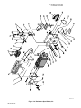
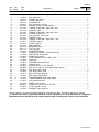
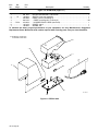
SECTION 7 − PARTS LIST 17 . . . . . . . . . . . . . . . . . . . . . . . . . . . . . . . . . . . . . . . . . . . . . . . . . . . . . . . . . . . . . . . . . . . . .
OPTIONS AND ACCESSORIES
WARRANTY

Notes

OM-745 Page 1
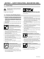
SECTION 1 − SAFETY PRECAUTIONS - READ BEFORE USING
spotom _nd_8/03
1-1. Symbol Usage
Means Warning! Watch Out! There are possible hazards
with this procedure! The possible hazards are shown in
the adjoining symbols.
Y Marks a special safety message.
. Means “Note”; not safety related.
This group of symbols means Warning! Watch Out! possible
ELECTRIC SHOCK, MOVING PARTS, and HOT PARTS hazards.
Consult symbols and related instructions below for necessary actions
to avoid the hazards.
1-2. Resistance Spot Welding Hazards
Y The symbols shown below are used throughout this manual to
call attention to and identify possible hazards. When you see
the symbol, watch out, and follow the related instructions to
avoid the hazard. The safety information given below is only
a summary of the more complete safety information found in
the Safety Standards listed in Section 1-5. Read and follow all
Safety Standards.
Y Only qualified persons should install, operate, maintain, and
repair this unit.
Y During operation, keep everybody, especially children, away.
SPOT WELDING can cause fire.
Sparks can fly off from the weld. The flying sparks,
hot workpiece, and hot equipment can cause fires,
burns, and explosions.
D Protect yourself and others from flying sparks and hot metal.
D Do not spot weld where flying sparks can strike flammable material.
D Remove all flammables within 35 ft (10.7 m) of the weld. If this is not
possible, tightly cover them with approved covers.
D Be alert that welding sparks can easily go through small cracks and
openings to adjacent areas.
D Watch for fire, and keep a fire extinguisher nearby.
D Do not spot weld on closed containers such as tanks or drums.
D Do not weld where the atmosphere may contain flammable dust,
gas, or liquid vapors (such as gasoline).
D Remove any combustibles, such as a butane lighter or matches,
from your person before doing any welding.
D After completion of work, inspect area to ensure it is free of sparks,
glowing embers, and flames.
D Do not exceed the equipment rated capacity.
D Use only correct fuses or circuit breakers. Do not oversize or
bypass them.
Touching live electrical parts can cause fatal shocks
or severe burns. The input power circuit and
machine internal circuits are also live when power is
on. Incorrectly installed or improperly grounded
equipment is a hazard.
ELECTRIC SHOCK can kill.
D Do not touch live electrical parts.
D Wear dry, hole-free insulating gloves and body protection.
D Disconnect input power before installing or servicing this equip-
ment. Lockout/tagout input power according to OSHA 29 CFR
1910.147 (see Safety Standards).
D Properly install and ground this equipment according to this manual
and national, state, and local codes.
D Check and be sure that input power cord ground wire is properly
connected to ground terminal in disconnect box or that cord plug is
connected to a properly grounded receptacle outlet − always
double-check the supply ground before applying power.
D When making input connections, attach the grounding conductor
first − double-check connections.
D Keep cords dry, free of oil and grease, and protected from hot metal
and sparks.
D Frequently inspect input power cord and ground conductor for dam-
age or bare wiring − replace immediately if damaged − bare wiring
can kill. Check ground conductor for continuity.
D Turn off all equipment when not in use.
D For water-cooled equipment, check and repair or replace any leak-
ing hoses or fittings. Do not use any electrical equipment if you are
wet or in a wet area.
D Use only well-maintained equipment. Repair or replace damaged
parts at once.
D Wear a safety harness if working above floor level.
D Keep all panels, covers, and guards securely in place.
Very often sparks fly off from the joint area.
D Wear approved face shield or safety goggles
with side shields.
FLYING SPARKS can cause injury.
D Wear protective garments such as oil-free, flame-resistant leather
gloves, heavy shirt, cuffless trousers, high shoes, and a cap.
Synthetic material usually does not provide such protection.
D Protect others in nearby areas by using approved flame-resistant or
noncombustible fire curtains or shields. Have all nearby persons
wear safety glasses with side shields.
Wear gloves or allow cooling period before servicing
tongs or tips.
D Always wear welding-type, insulated gloves
when using this equipment.
HOT METAL can cause burns.
D Do not touch workpiece, tips, or tongs with bare hands.
D Allow tongs and tips to cool before touching.

OM-745 Page 2
The tong tips, tongs, and linkages move during
operation.
MOVING PARTS can cause injury.
D Keep away from moving parts.
D Keep away from pinch points.
D Do not put hands between tips.
D Keep all guards and panels securely in place.
D OSHA and/or local codes may require additional guarding to suit
the application.
FUMES can be hazardous.
Coatings, cleaners, paints, and platings can pro-
duce fumes when welded. Breathing these fumes
can be hazardous to your health.
D Do not breathe the fumes.
D If inside, ventilate the area and/or use exhaust at the weld to remove
fumes.
D In confined spaces, use an approved air-supplied respirator.
D Do not weld on coated metals, such as galvanized, lead, or cad-
mium plated steel, unless the coating is removed from the weld
area, the area is well ventilated, or if necessary, while wearing an
air-supplied respirator. The coatings and any metals containing
these elements can give off toxic fumes if welded.
D Read the Material Safety Data Sheets (MSDSs) and the manufac-
turer’s instructions for metals, coatings, and cleaners.
1-3. Additional Symbols For Installation, Operation, And Maintenance
FIRE OR EXPLOSION hazard.
D Do not install or place unit on, over, or near
combustible surfaces.
D Do not install or operate unit near flammables.
D Do not overload building wiring − be sure power supply system is
properly sized, rated, and protected to handle this unit.
FALLING EQUIPMENT can cause injury.
D Use equipment of adequate capacity to lift the
unit.
D Have two people of adequate physical strength
lift portable units.
D Secure unit during transport so it cannot tip or fall.
FLYING METAL or DIRT can injure eyes.
D Wear approved safety glasses with side
shields or wear face shield.
MAGNETIC FIELDS can affect pacemakers.
D Pacemaker wearers keep away.
D Wearers should consult their doctor before go-
ing near resistance spot welding operations.
OVERUSE can cause OVERHEATING.
D Allow cooling period; follow rated duty cycle.
D Reduce duty cycle before starting to weld
again.
1-4. California Proposition 65 Warnings
Y Welding or cutting equipment produces fumes or gases which
contain chemicals known to the State of California to cause
birth defects and, in some cases, cancer. (California Health &
Safety Code Section 25249.5 et seq.)
Y Battery posts, terminals and related accessories contain lead
and lead compounds, chemicals known to the State of
California to cause cancer and birth defects or other
reproductive harm. Wash hands after handling.
For Gasoline Engines:
Y Engine exhaust contains chemicals known to the State of
California to cause cancer, birth defects, or other reproductive
harm.
For Diesel Engines:
Y Diesel engine exhaust and some of its constituents are known
to the State of California to cause cancer, birth defects, and
other reproductive harm.
1-5. Principal Safety Standards
Safety in Welding and Cutting, ANSI Standard Z49.1, from American
Welding Society, 550 N.W. LeJeune Rd, Miami FL 33126
Safety and Health Standards, OSHA 29 CFR 1910, from Superinten-
dent of Documents, U.S. Government Printing Office, Washington, D.C.
20402.
National Electrical Code, NFPA Standard 70, from National Fire Protec-
tion Association, Batterymarch Park, Quincy, MA 02269.
Code for Safety in Welding and Cutting, CSA Standard W117.2, from
Canadian Standards Association, Standards Sales, 178 Rexdale Bou-
levard, Rexdale, Ontario, Canada M9W 1R3.
Safe Practices For Occupation And Educational Eye And Face Protec-
tion, ANSI Standard Z87.1, from American National Standards Institute,
1430 Broadway, New York, NY 10018.
Cutting And Welding Processes, NFPA Standard 51B, from National
Fire Protection Association, Batterymarch Park, Quincy, MA 02269.
1-6. EMF Information
Considerations About Welding And The Effects Of Low Frequency
Electric And Magnetic Fields
Welding current will cause electromagnetic fields. There has been and
still is some concern about such fields. However, after examining more
than 500 studies spanning 17 years of research, a special blue ribbon
committee of the National Research Council concluded that: “The body
of evidence, in the committee’s judgment, has not demonstrated that
exposure to power-frequency electric and magnetic fields is a human-
health hazard.” However, studies are still going forth and evidence
continues to be examined.

OM-745 Page 3
SECTION 2 − CONSIGNES DE SÉCURITÉ − LIRE AVANT
UTILISATION
spot_fre 8/03
2-1. Signification des symboles
Signifie Mise en garde ! Soyez vigilant ! Cette procédure
présente des risques de danger ! Ceux-ci sont identifiés
par des symboles adjacents aux directives.
Y Identifie un message de sécurité particulier.
. Signifie NOTA ; n’est pas relatif à la sécurité.
Ce groupe de symboles signifie Mise en garde ! Soyez vigilant ! Il y
a des risques de danger reliés aux CHOCS ÉLECTRIQUES, aux
PIÈCES EN MOUVEMENT et aux PIÈCES CHAUDES. Reportez-
vous aux symboles et aux directives ci-dessous afin de connaître les
mesures à prendre pour éviter tout danger.
2-2. Dangers liés au soudage par points
Y Les symboles représentés ci-dessous sont utilisés dans ce
manuel pour attirer l’attention et identifier les dangers possi-
bles. Lorsque vous rencontrez un symbole, prenez garde et
suivez les instructions afférentes pour éviter tout risque. Les
instructions en matière de sécurité indiquées ci-dessous ne
constituent qu’un sommaire des instructions de sécurité plus
complètes fournies dans la normes de sécurité énumérées
dans la Section 2-4. Lisez et observez toutes les normes de sé-
curité.
Y Seul un personnel qualifié est autorisé à installer, faire fonc-
tionner, entretenir et réparer cet appareil.
Y Pendant le fonctionnement, maintenez à distance toutes les
personnes, notamment les enfants de l’appareil.
LE SOUDAGE PAR POINTS peut
provoquer un incendie.
Des étincelles peuvent être projetées de la soudure.
La projection d’étincelles ainsi que les pièces et
équipements chauds peuvent provoquer des
incendies, des brûlures et des incendies.
D Protégez-vous, ainsi que toute autre personne travaillant sur les
lieux, contre les étincelles et le métal chaud.
D Ne soudez pas par points dans un endroit où des étincelles peuvent
tomber sur des substances inflammables.
D Déplacez toute matière inflammable se trouvant dans un périmètre
de 10 m de la pièce à souder. Si cela est impossible, couvrez-les de
housses approuvées et bien ajustées.
D Des étincelles du soudage peuvent facilement passer dans
d’autres zones en traversant de petites fissures et des ouvertures.
D Afin d’éliminer tout risque de feu, soyez vigilant et gardez toujours
un extincteur à portée de main.
D Ne soudez pas par points sur un récipient fermé tel un réservoir ou
un bidon.
D Ne soudez pas si l’air ambiant est chargé de particules, gaz, ou
vapeurs inflammables (vapeur d’essence, par exemple).
D Avant de souder, retirez toute substance combustible de vos
poches telles qu’un briquet au butane ou des allumettes.
D Une fois le travail achevé, assurez-vous qu’il ne reste aucune trace
d’étincelles incandescentes ni de flammes.
D Ne dépassez pas la puissance permise de l’équipement.
D Utiliser exclusivement des fusibles ou coupe-circuits appropriés.
Ne pas augmenter leur puissance; ne pas les ponter.
Le fait de toucher à une pièce électrique sous
tension peut donner une décharge fatale ou entraî-
ner des brûlures graves. L’alimentation d’entrée et
les circuits internes de l’appareil sont également
actifs lorsque le poste est sous tension. Un poste
incorrectement installé ou inadéquatement mis à la terre constitue un
danger.
UNE DÉCHARGE ÉLECTRIQUE peut
entraîner la mort.
D Ne touchez pas aux pièces électriques sous tension.
D Portez des gants isolants et des vêtements de protection secs et
sans trous.
D Coupez l’alimentation d’entrée avant d’installer l’appareil ou
d’effectuer l’entretien. Verrouillez ou étiquetez la sortie d’alimenta-
tion selon la norme OSHA 29 CFR 1910.147(reportez-vous aux
Principales normes de sécurité).
D Installez le poste correctement et mettez-le à la terre
conformément aux consignes de ce manuel et aux normes
nationales, provinciales et locales.
D Assurez-vous que le fil de terre du cordon d’alimentation est
correctement relié à la borne de terre du sectionneur ou que la fiche
du cordon est branchée à une prise correctement mise à la terre −
vous devez toujours vérifier la mise à la terre avant toute mise sous
tension.
D Avant d’effectuer les connexions d’alimentation, vous devez
connecter en premier lieu le fil de terre - contrôlez les connexions.
D Les câbles doivent être exempts d’humidité, d’huile et de graisse;
protégez-les contre les étincelles et les pièces métalliques
chaudes.
D Assurez-vous régulièrement que les câbles d’alimentation et de
masse ne sont pas endommagés ou dénudé par endroit. Rempla-
cez-les immédiatement si c’est le cas : un câble dénudé peut
provoquer la mort. Contrôlez la continuité de la mise à la terre.
D L’équipement doit être hors tension lorsqu’il n’est pas utilisé.
D Dans le cas d’équipements refroidis par eau, contrôlez les
conduites et raccords; remplacez-les s’ils présentent des fuites.
N’utilisez pas d’équipement électrique si vous êtes mouillé ou dans
une zone humide.
D Utilisez uniquement un équipement en bonne condition. Réparez
ou remplacez immédiatement toute pièce endommagée.
D Portez un harnais de sécurité si vous devez travailler au-dessus du
sol.
D Maintenez en place les panneaux, couvercles et protections de
sécurité.
Des étincelles peuvent jaillir de la soudure.
D Portez une visière ou des lunettes de sécurité
avec des écrans latéraux approuvées.
LES ÉTINCELLES VOLANTES
risquent de provoquer des blessures.
D Portez un équipement de protection: gants en cuir résistant au feu,
chemise épaisse, pantanlons sans revers, chaussures de sécurité
et casquette. Les matériaux synthétiques ne garantissent pas une
bonne protection.
D Protégez les autres occupants du local à l’aide d’un rideau ou d’un
écran ignifuge approprié. Assurez-vous que ces personnes portent
des lunettes de sécurité avec protections latérales.
Portez des gants ou laissez refroidir les électrodres
avant de procéder à l’entretien.
D Portez toujours de gants de soudeur lorsque
vous utilisez cet équipement.
LE MÉTAL CHAUD peut provoquer
des brûlures.
D Ne touchez pas les pièces ni les eléctrodes avec les mains.
D Laissez les électrodes refroidir avant de les toucher.

OM-745 Page 4
DES ORGANES MOBILES peuvent
provoquer des blessures.
Pendant le soudage, les bras et électrodes se
déplacent.
D Ne pas s’approcher des organes mobiles.
D Ne pas s’approcher des points de coincement.
D Ne placez pas les mains entre les électrodes.
D Maintenez en place les panneaux et protections de sécurité.
D Les applications peuvent nécessiter des protections
supplémentaires d’après les codes de sécurité locales.
LES FUMÉES peuvent être
dangereuses.
Lors du soudage, les revêtements, produits de net-
toyage, peintures et placages peuvent dégager des
fumées. Leur inhalation peut être dangereuse.
D Ne respirez pas les fumées.
D Si vous soudez à l’intérieur, ventilez le local et/ou ayez recours à
une ventilation aspirante installée près de la soudure pour évacuer
les fumées.
D Dans des lieux exigus, utilisez un appareil respiratoire approprié.
D Ne pas souder des métaux munis d’un revêtement, tels que l’acier
galvanisé, plaqué en plomb ou au cadmium à moins que le revêtement
n’ait été enlevé dans la zone de soudure, que l’endroit soit bien ventilé,
et si nécessaire, en portant un respirateur à alimentation d’air. Les
revêtements et tous les métaux renfermant ces éléments peuvent
dégager des fumées toxiques en cas de soudage.
D Veuillez lire les consignes de sécurité et les instructions du
fabricant pour les métaux, revêtements et produits de nettoyage.
2-3. Dangers supplémentaires en relation avec l’installation, le fonctionnement et la
maintenance
Risque D’INCENDIE OU
D’EXPLOSION.
D Ne pas placer l’appareil sur, au-dessus ou à
proximité de surfaces infllammables.
D Ne pas installer ni faire fonctionner l’appareil à
proximité de substances inflammables.
D Ne pas surcharger l’installation électrique − s’assurer que
l’alimentation est correctement dimensionnée et protégée avant
de mettre l’appareil en service.
LA CHUTE DE L’ÉQUIPEMENT peut
blesser.
D Utiliser un engin d’une capacité appropriée
pour soulever l’appareil.
D Faites déplacer les équipements portables par
deux personnes dotées d’une force suffisante.
D Durant le transport, immobilisez l’appareil pour éviter qu’il ne
bascule.
DES PIÈCES DE MÉTAL ou DES
SALETÉS peuvent provoquer des
blessures aux yeux.
D Porter des lunettes de sécurité à coques latéra-
les ou un écran facial.
LES CHAMPS MAGNÉTIQUES peuvent
affecter les stimulateurs cardiaques.
D Porteurs de stimulateur cardiaque, restez à
distance.
D Les porteurs d’un stimulateur cardiaque doi-
vent d’abord consulter leur médecin avant de
s’approcher des opérations de soudage par
points.
L’EMPLOI EXCESSIF peut
SURCHAUFFER L’ÉQUIPEMENT.
D Prévoir une période de refroidissement;
respecter le cycle opératoire nominal.
D Réduire le facteur de marche avant de poursui-
vre le soudage.
2-4. Principales normes de sécurité
Safety in Welding and Cutting, norme ANSI Z49.1, de l’American Wel-
ding Society, 550 N.W. Lejeune Rd, Miami FL 33126
Safety and Health Sandards, OSHA 29 CFR 1910, du Superintendent
of Documents, U.S. Government Printing Office, Washington, D.C.
20402.
National Electrical Code, NFPA Standard 70, de la National Fire Protec-
tion Association, Batterymarch Park, Quincy, MA 02269.
Règles de sécurité en soudage, coupage et procédés connexes, norme
CSA W117.2, de l’Association canadienne de normalisation, vente de
normes, 178 Rexdale Boulevard, Rexdale (Ontario) Canada M9W 1R3.
Safe Practices For Occupation And Educational Eye And Face Protec-
tion, norme ANSI Z87.1, de l’American National Standards Institute,
1430 Broadway, New York, NY 10018.
Cutting and Welding Processes, norme NFPA 51B, de la National Fire
Protection Association, Batterymarch Park, Quincy, MA 02269.
2-5. Information sur les champs électromagnétiques
Données sur le soudage électrique et sur les effets, pour l’organisme,
des champs magnétiques basse fréquence
L’extrait suivant est tiré des conclusions générales du document intitulé
Biological Effects of Power Frequency Electric & Magnetic Fields −
Background Paper, OTA-BP-E-53 (Washington DC : U.S. Government
Printing Office, mai 1989), publié par le Office of Technology Asses-
sment du Congrès américain : «... il existe maintenant d’abondantes
données scientifiques compilées à la suite d’expériences sur la cellule
ou d’études sur des animaux et des humains, qui montrent clairement
que les champs électromagnétiques basse fréquence peuvent avoir
des effets sur l’organisme et même y produire des transformations.
Même s’il s’agit de travaux de très grande qualité, les résultats sont
complexes. Cette démarche scientifique ne nous permet pas d’établir
un tableau d’ensemble cohérent. Pire encore, elle ne nous permet pas
de tirer des conclusions finales concernant les risques éventuels, ni
d’offrir des conseils sur les mesures à prendre pour réduire sinon élimi-
ner les risques éventuels». (Traduction libre)

OM-745 Page 5
SECTION 3 − INSTALLATION
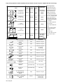
3-1. Specifications
In
p
ut Work
Rated Output Amperes
ATT
Input
Voltage
50/60 H
In
put
Work
Capacity
Cbid
Rated Output
At Li t d
Rated Output Amperes
At Listed Tong Length
Open-
Ci it
ATT
Models
g
50/60 Hz
AC
1-Phase
Input
Amps
py
Combined
Thickness
Mild Steel
p
At Listed
Duty Cycle*
6 in
(152 mm)
12 in
(305 mm)
18 in
(457 mm)
p
Circuit
Voltage
SSW-2020
230 90
1/4 in
(6.3 mm)
20 kVA
40%
12,500 10,500 9000 3.55
SSW-2040
460 45
1/4 in
(6.3 mm)
20 kVA
40%
12,500 10,500 9000 3.55
*Based on 10 second time period; means unit can weld for 5 seconds out of each 10 second time period.
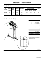
3-2. Dimensions And Weight
Ref. 802 751
*Dimension depends upon length of tongs.
See Parts List for sizes.
A
B
D
E
F
GH
J
J
Dimensions
A 49 in (1245 mm)
B 37-1/8 in (943 mm)
C*
D 10-7/8 in (276 mm)
E 9-1/2 in (241 mm)
F 11/16 in (18 mm)
G 19-1/2 in (495 mm)
H 20-7/8 in (530 mm)
I 11/16 in (18 mm)
J 1/2 in (13 mm)
Dia. 4 Holes
SSW-2020, 2040 185 lb (84 kg)
Weight
C
Y Bolt unit to floor to keep
it from falling over.

OM-745 Page 6
3-3. Moving The Spot Welder
802 752
1 Rating Label
Locate unit near correct input
power supply.
2 Skid
Place unit on skid and secure with
straps.
2
1
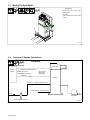
3-4. Overview Of System Connections
802 792-A
Spotwelder
system
Coolant
Air in
Coolant line (see Section 2-6)
Coolant line
Pedestal
Normally 5/8−18 left−
hand threaded receptacles
Input power line (see Section 2-8)
Air hose 60 − 100 PSI (see Section 2-10)
Slip−on hoses
tighten with
hose clamps
Foot switch
Air filter/regulator assembly
SSW Models

OM-745 Page 7
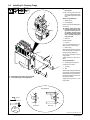
3-5. Installing Or Cleaning Tongs
Y Turn off unit and disconnect
input power.
. Be sure tong ends are clean
and not corroded before instal-
ling. Clean tongs with fine steel
wool.
Bottom Tong Installation:
1 Spatter Guard
2 Insulating Strip
Check to see that insulating strip is
not cracked.
Y Electric shock hazard and
possible transformer dam-
age from incorrect part. Do
not replace polyester glass
insulating strip with a metal
strip − use only proper parts
from Parts List.
3 Setscrew
Loosen setscrew.
4 Cam Nut
Turn nut counterclockwise to re-
lease pressure on bottom tong.
5 Bottom Tong
Slide tong into bottom tong holder
as far as possible, and position so
that tip is pointing straight up.
Turn cam nut clockwise to secure
tong in holder.
Tighten setscrew to lock cam in
place.
Top Tong Installation:
6 Top Tong Securing Screws
Loosen the four screws.
7 Top Tong
8 Tips
Slide tong into top tong holder as far
as necessary, so that tip mates with
bottom tip when tongs are closed.
Adjust tong positions to line up cen-
ters of tips as shown.
Tighten securing screws to lock
tong in place.
802 754 / 801 436 / Ref. 800 154-A
3/16 in
9/16 in
Fine
Steel
Wool
5
7
7
5
8
8
Front View Side View
Tong Alignment
1
6
7
5
4
3
2
Y OSHA and/or local codes may require addi-
tional guarding to suit the application.

OM-745 Page 8
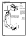
3-6. Coolant Connections
Y Turn off power and coolant
supply until installation is
complete.
1 Tong Coolant Hose
2 Hose Clamp
3 Barbed Fitting
4 Coolant-In Fitting
5 Coolant-In Hose
6 Coolant-Out Hoses
7 Coolant System
Connect hoses to coolant system
(see coolant system owner’s
manual).
. This unit is equipped with a
water control pressure switch
to insure proper cooling. If
there is not enough pressure to
close the switch, the unit will
not weld. For proper operation,
coolant supply must have a
minimum pressure of 30 psi
(207 kPa), a maximum temper-
ature of 86° F (30° C), and a
flow rate of 2.5 to 3 qt/min (2.4
to 2.8 L/min).
Ref. 802 755 / Ref. 802 758-A
5/8 in
1
23
6
5
. It is recommended that a coolant which contains
a base of ethylene glycol and deionized water
such as low-conductivity coolant solution, Part
No. 043 810, be used to protect against freezing
to -37 F (-38 C) or boiling to 227 F (108 C). It
also contains a compound that resists algae
growth.
4
7

OM-745 Page 9
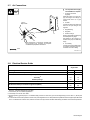
3-7. Air Connections
Ref. 802 761-A
Y Turn off power and air supply
until installation is complete.
1 Air Hoses (Customer
Supplied)
Obtain two hoses of correct size,
type, and length. Air-In fittings on
control boxes have 1/4 in pipe
threads.
2 Air Filter
Connect one hose to air supply and
other end to input fitting on the
regulator.
3 Regulator Plug
4 Regulator
5 Pressure Gauge
Remove appropriate regulator plug
and install pressure gauge.
Set regulator so air pressure is in
the 60 to 100 psi (414 to 689 kPa)
range.
6 Air-In Fitting
Connect one end of remaining hose
to regulator output fitting, and con-
nect other end to Air-In fitting.
1
See manufacturer’s instructions supplied with
filter/regulator (FR) assembly for complete
installation and preparation instructions.
6
5
2
3
5/8 in
1
1/4 Inch Pipe Thread
1/4 Inch
Pipe Thread
3-8. Electrical Service Guide
20 KVA
Single Phase
Input Voltage 230 460
Input Amperes At Rated Output 90 45
Max Recommended Standard Fuse Rating In Amperes
1
Time-Delay
2
110 50
Normal Operating 3 125 70
Min Input Conductor Size In AWG/Kcmil
4
6 10
Max Recommended Input Conductor Length In Feet (Meters)
78
(24)
131
(40)
Min Grounding Conductor Size In AWG/Kcmil
4
6 10
Reference: 1999 National Electrical Code (NEC)
1 Consult factory for circuit breaker applications.
2 “Time-Delay” fuses are UL class “RK5” .
3 “Normal Operating” (general purpose - no intentional delay) fuses are UL class “K5” (up to and including 60 amp), and UL class “H” ( 65 amp and
above).
4 Conductor data in this section specifies conductor size (excluding flexible cord or cable) between the panelboard and the equipment per NEC Table
310.16. If a flexible cord or cable is used, minimum conductor size may increase. See NEC Table 400.5(A) for flexible cord and cable requirements.

OM-745 Page 10
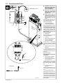
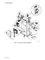
3-9. Connecting Input Power
Y Installation must meet all
National and Local Codes −
have only qualified persons
make this installation.
Y Disconnect and lockout/
tagout input power before
connecting input conduc-
tors from unit.
Y Always connect green or
green/yellow conductor to
supply grounding terminal
first, and never to a line ter-
minal.
See rating label on unit and check
input voltage available at site.
Remove left side panel.
1 Input Power Conductors
(Customer Supplied Cord)
Select size and length of conduc-
tors using Section 3-8. Conductors
must comply with national, state,
and local electrical codes. If appli-
cable, use lugs of proper amper-
age capacity and correct hole size.
Welding Power Source Input
Power Connections
2 Strain Relief
Route conductors (cord) through
strain relief and tighten.
3 Contactor
4 Machine Grounding Terminal
5 Green Or Green/Yellow
Grounding Conductor
Connect green or green/yellow
grounding conductor to welding
power source grounding terminal
first.
6 Welding Power Source Line
Terminals
7 Input Conductors L1 And L2
Connect input conductors L1 and
L2 to welding power source line
terminals.
Reinstall side panel.
Disconnect Device Input Power
Connections
8 Disconnect Device (switch
shown in OFF position)
9 Disconnect Device (Supply)
Grounding Terminal
Connect green or green/yellow
grounding conductor to discon-
nect device grounding terminal
first.
10 Disconnect Device Line
Terminals
Connect input conductors L1 And
L2 to disconnect device line termi-
nals.
11 Over-Current Protection
Select type and size of over-cur-
rent protection using Section 3-8
(fused disconnect switch shown).
Close and secure door on line dis-
connect device. Remove lockout/
tagout device, and place switch in
the On position.
Ref. 802 760
8
7
3/8, 1/2 in
L1
L2
1
3
6
5
4
Tools Needed:
= GND/PE Earth Ground
1
2
=GND/PE Earth Ground
5
7
9
10
7
11

OM-745 Page 11
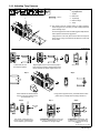
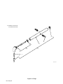
3-10. Adjusting Tong Pressure
Y Turn off power before mak-
ing adjustments.
1 Top Nut
2 Bottom Nut
3 Top Linkage
4 Bottom Linkage
5 Tongs
. Tong pressure must be checked and/or set before operation.
Correct tong pressure is necessary to create a quality weld and to
prevent damage to tips.
Too much tong pressure causes the weld nugget to dimple and ma-
terial to splash out around the nugget area.
If tong pressure is too weak, parts are loose when the tongs are
closed, severe arcing occurs between workpieces, and no weld
can be made.
Ref. 802 762-A / Ref. 161 768-B
Step 1 Step 2
Step 3
Step 4 Step 5
Step 6 Step 7
Air Supply
Air Supply On
13/16 in
Loosen both nuts and
push tong tips together.
Begin to tighten top nut. This causes tong tips to
open. Stop when opening is a little less than thick-
ness of material to be welded. Tighten bottom nut.
Set controls.
If tong pressure appears correct, place Weld switch in Weld
position and try a sample weld according to Section 4-1.
Set controls. If tong pressure is
correct, stop here. If further adjust-
ment is required, go to next step.
To INCREASE tong pressure, loosen top
nut 1/4 turn. Tighten bottom nut, turn air
and Power On, and go to Step 4.
Off
Step 8
To DECREASE tong pressure, loos-
en bottom nut 1/4 turn. Tighten top
nut, turn air and Power On, and go
to Step 4.
Place material to be welded between
tong tips, and press remote foot con-
trol (see Section 4-1).
4
3
1
2
5

OM-745 Page 12
SECTION 4 − OPERATION
4-1. Controls
802 751 / 200 264-A
1 Time Control
Squeeze Time (ST) - Use control to set
enough time for tongs to close and apply full
pressure to the work before weld amperage
starts. Push ST button, then use buttons 3,
2, 1 to select squeeze time from 0 to 9.99 se-
conds. Squeeze time begins when the Re-
mote Foot Switch or Start Switch is pressed.
Weld Time (WT) - Push WT button, then use
buttons 3, 2, 1 to select spot weld time from
0 to 9.99 seconds.
Weld time begins at the end of the squeeze
time cycle.
2 Weld Switch
Use control to check tong pressure and
alignment without weld amperage present at
the tongs. When the switch is in the Set Up
position, pressing the Remote Foot Switch
closes the tongs without starting weld am-
perage. When the switch is in the Weld posi-
tion, tongs have weld amperage present af-
ter the squeeze time has ended.
3 Weld Amperage Control
Turn clockwise to increase current. Chang-
ing the weld current value does not affect the
duty cycle rating. The scale is for reference
only.
4 Power/Pilot Light/Circuit Breaker
Switch
Use switch to turn On power and pilot light.
See Section 5-2 for circuit breaker operation.
5 Fuse F1
See Section 5-2.
6 Remote Foot Switch
Use remote foot switch to close tongs and
start squeeze time.
If switch is released before squeeze time
ends, the tongs open, and the unit resets for
another weld cycle.
If switch is held until squeeze time ends and
weld time starts, the switch may be released,
and the tongs will stay closed until weld time
ends.
If workpiece is to be left between tongs after
weld time ends, switch must be held for
whatever hold time is desired after welding
ends.
6
4
1
2
3
5
Second row of LCDs
displays squeeze time
set or weld time set.
First row of LCDs displays
actual time set.
ST
WT
4321

OM-745 Page 13
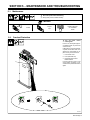
SECTION 5 − MAINTENANCE AND TROUBLESHOOTING
5-1. Maintenance
Y Disconnect power before maintaining.
. During heavy service, maintain monthly.
3 Months
Oil Unit
Replace Damaged
Or Unreadable
Labels
Inspect
Tips
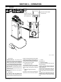
5-2. Overload Protection
802 763
Y Turn Off power before
checking fuse.
Fuse F1 and Power/pilot light/cir-
cuit breaker switch S1 protect the
control circuitry.
If either the fuse or the circuit break-
er opens, the unit shuts down. Turn
switch On to reset breaker. To re-
place a fuse, proceed as shown:
1 Fuse Holder Cover
2 Fuse (See Parts List)
3 Power/Pilot Light /Circuit
Breaker Switch
If a fuse continues to open, or the
circuit breaker continues to trip,
contact Factory Authorized Service
Agent.
1
2
3

OM-745 Page 14
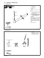
5-3. Installing Or Dressing Tips
ST-801 437
Y Turn off power before re-
moving tips.
1Tip
2 Telescoping Tube
Removal:
Tips have a Morse Taper and a
press fit.
. Use a vice grip pliers to rotate
and loosen tips. Once loose,
pull tips straight out.
Y Do not move tips from side to
side when removing or tele-
scoping tube will snap off.
Installation:
Coat taper area of tip with pipe
sealant compound. Pull tele-
scoping tube all the way up, but not
out. Use a plastic or leather
hammer to tap tip into seat. Run
water through tong to check for
leaks.
Repeat if necessary.
1
2
A. Installing Tips
B. Dressing Tips
1 New Tip
2 Used Tip Requiring Dressing
3 Dressing Method − Keep top
diameter same as a new tip.
1
d = 3/16−1/4 in (4.8−6.4 mm)
diameter
2
3d d
OR

OM-745 Page 15
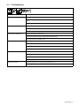
5-4. Troubleshooting
Trouble Remedy
No weld output; pilot light Off. Check line fuses, and replace if necessary (see Section 3-9).
Check fuse F1 and/or Power/pilot light/circuit breaker switch S1, and replace if necessary (see Section
5-2).
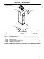
Turn On Power/pilot light/circuit breaker switch S1.
No weld output, pilot light on. Check for proper coolant supply pressure (see Section 3-6).
Place Weld Switch S3 in the Weld position (see Section 4-1).
Have Factory Authorized Service Agent check contactor W.
Low weld output; pilot light On. Dress or replace tips (see Section 5-3).
Remove and clean ends of tongs and tong holders (see Section 3-5).
Adjust tong pressure (see Section 3-10).
Longer than normal Weld Time required. Dress or replace tong tips (see Section 5-3).
Clean workpieces.
Adjust tong pressure (see Section 3-10).
Check input line voltage.
Burn through at point of weld. Shorten weld time (see Section 4-1).
Adjust tong pressure (see Section 3-10).
Dress or replace tong tips (see Section 5-3).
Realign tips (see Section 3-5).
Tongs close too slowly. Check air pressure at source and at regulator (see Section 3-7).
Have Factory Authorized Service Agent check and replace air valve, if necessary.

OM-745 Page 16
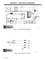
SECTION 6 − ELECTRICAL DIAGRAMS
199 202
Figure 6-1. Circuit Diagram For Stationary Models
200 302-A
Figure 6-2. Circuit Diagram For Foot Control
La page est en cours de chargement...
La page est en cours de chargement...
La page est en cours de chargement...
La page est en cours de chargement...
La page est en cours de chargement...
La page est en cours de chargement...
La page est en cours de chargement...
La page est en cours de chargement...
La page est en cours de chargement...
La page est en cours de chargement...
La page est en cours de chargement...
La page est en cours de chargement...
-
 1
1
-
 2
2
-
 3
3
-
 4
4
-
 5
5
-
 6
6
-
 7
7
-
 8
8
-
 9
9
-
 10
10
-
 11
11
-
 12
12
-
 13
13
-
 14
14
-
 15
15
-
 16
16
-
 17
17
-
 18
18
-
 19
19
-
 20
20
-
 21
21
-
 22
22
-
 23
23
-
 24
24
-
 25
25
-
 26
26
-
 27
27
-
 28
28
-
 29
29
-
 30
30
-
 31
31
-
 32
32


Miller LF161832 Le manuel du propriétaire
- Catégorie
- Système de soudage
- Taper
- Le manuel du propriétaire
- Ce manuel convient également à
dans d''autres langues
- English: Miller LF161832 Owner's manual