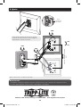
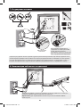
Tripp Lite Full Motion Flat Screen Wall Mount Le manuel du propriétaire
- Catégorie
- Supports muraux à panneau plat
- Taper
- Le manuel du propriétaire

1
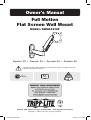
Owner’s Manual
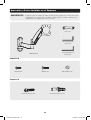
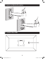
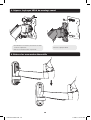
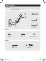
Full Motion
Flat Screen Wall Mount
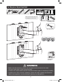
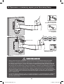
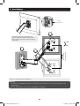
MODEL: DWM1327SP
CAUTION: DO NOT EXCEED MAXIMUM LISTED WEIGHT CAPACITY. SERIOUS INJURY OR
PROPERTY DAMAGE MAY OCCUR!
1111 W. 35th Street, Chicago, IL 60609 USA • www.tripplite.com/support
Copyright © 2014 Tripp Lite. All rights reserved.
75x75
100x100
27”
MAX
15 kg
(33 lbs)
Español 12 • Français 23 • Русский 34 • Deutsch 45
14-04-249-93332D.indb 1 5/9/2014 9:37:34 AM

2
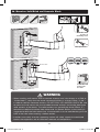
NOTE: Read the entire instruction manual before you start installation and assembly.
Warranty & Warranty Registration
WARNING
• Do not begin the installation until you have read and understood the instructions
and warnings contained in this manual. If you have any questions regarding any
of the instructions or warnings, please visit www.tripplite.com/support.
• This mounting bracket was designed to be installed and utilized ONLY as
specified in this manual. Improper installation of this product may cause damage
or serious injury.
• This product should only be installed by someone of good mechanical ability,
with basic building experience and a full understanding of this instruction
manual.
• Make sure that the mounting surface can safely support the combined load of
the equipment and all attached hardware and components.
• If mounting to wood wall studs, make sure that mounting screws are anchored
into the center of the studs. The use of a stud finder is highly recommended.
• Always use an assistant or mechanical lifting equipment to safely lift and position
equipment.
• Tighten screws rmly, but do not over-tighten. Over-tightening can damage the
items, greatly reducing their holding power.
• This product is intended for indoor use only. Using this product outdoors could
lead to product failure and personal injury.
5-Year Limited Warrant
Seller warrants this product, if used in accordance with all applicable instructions, to be free from original defects
in material and workmanship for a period of 5 years from the date of initial purchase. If the product should
prove defective in material or workmanship within that period, Seller will repair or replace the product, in its sole
discretion.
THIS WARRANTY DOES NOT APPLY TO NORMAL WEAR OR TO DAMAGE RESULTING FROM ACCIDENT, MISUSE,
ABUSE OR NEGLECT. SELLER MAKES NO EXPRESS WARRANTIES OTHER THAN THE WARRANTY EXPRESSLY
SET FORTH HEREIN. EXCEPT TO THE EXTENT PROHIBITED BY APPLICABLE LAW, ALL IMPLIED WARRANTIES,
INCLUDING ALL WARRANTIES OF MERCHANTABILITY OR FITNESS, ARE LIMITED IN DURATION TO THE WARRANTY
PERIOD SET FORTH ABOVE; AND THIS WARRANTY EXPRESSLY EXCLUDES ALL INCIDENTAL AND CONSEQUENTIAL
DAMAGES. (Some states do not allow limitations on how long an implied warranty lasts, and some states do not
allow the exclusion or limitation of incidental or consequential damages, so the above limitations or exclusions
may not apply to you. This warranty gives you specific legal rights, and you may have other rights which vary from
jurisdiction to jurisdiction).
WARNING: The individual user should take care to determine prior to use whether this device is suitable, adequate
or safe for the use intended. Since individual applications are subject to great variation, the manufacturer makes
no representation or warranty as to the suitability or fitness of these devices for any specific application.
WARRANTY REGISTRATION
Visit www.tripplite.com/warranty today to register the warranty for your new Tripp Lite product. You’ll be
automatically entered into a drawing for a chance to win a FREE Tripp Lite product!*
* No purchase necessary. Void where prohibited. Some restrictions apply. See website for details.
Tripp Lite has a policy of continuous improvement. Specifications are subject to change without notice.
14-04-249-93332D.indb 2 5/9/2014 9:37:34 AM

3
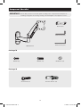
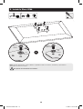
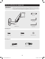
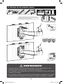
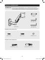
Component Checklist
IMPORTANT: Ensure that you have received all parts according to the component checklist prior to
installing. If any parts are missing or faulty, visit www.tripplite.com/support for service.
DWM1327SP
4mm Hex Key (x1)
Wrench (x1)
6mm Hex Key (x1)
D5 Washer (x4)M4X14 (x4)
Anchor Bolt (x3) Concrete Anchor (x3)
M5X14 (x4)
Package M
Package W
14-04-249-93332D.indb 3 5/9/2014 9:37:34 AM

4
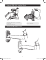
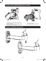
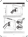
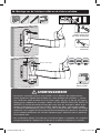
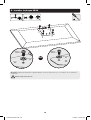
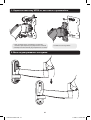
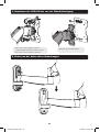
1. Separate VESA Plate from Wall Mount
2. Remove the Decorative Covers
• Using the supplied wrench, loosen the two
upper knobs
• Remove both lower knobs
Remove VESA plate.
D
14-04-249-93332D.indb 4 5/9/2014 9:37:35 AM

5
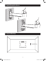
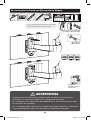
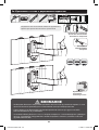
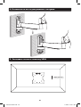
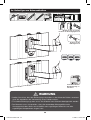
3a. Mount on Wood Stud Wall
3
Mark the exact location of the
mounting holes
Screw the wall
mount onto
the wall
Drill pilot holes
WARNING
• Make sure that mounting screws are anchored into the center of the studs.
Use of a stud finder is highly recommended.
• Installers are responsible to provide hardware for other types of mounting situations.
• Installers must verify that the supporting surface will safely support the combined
load of the equipment and all attached hardware and components.
Find a wood stud location for
mounting the wall mount
1
2
Anchor Bolt
14-04-249-93332D.indb 5 5/9/2014 9:37:35 AM

6
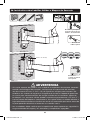
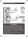
3b. Mount on Solid Brick and Concrete Block
WARNING
• When installing wall mounts onto a concrete masonry unit (also known as a CMU or
“cinder block”), verify that the actual concrete thickness is at least 35mm (1-3/8”)
in order to hold the concrete anchors. DO NOT DRILL INTO MORTAR JOINTS! Be sure
to mount the wall mount with the included concrete anchors and anchor bolts onto
solid sections of the blocks. The solid sections can generally be found 25mm (1”)
toward the middle of the block from either end. An electric drill on a slow setting is
suggested to drill the hole rather than a hammer drill so as to avoid breaking out the
back of the hole when entering a hollow section.
• Installers must verify that the supporting surface will safely support the combined
load of the equipment and all attached hardware and components.
Screw the wall
mount onto
the wall
Drill pilot holes
2
Mark the exact
location of
mounting holes
1
Concrete Anchor
Anchor Bolt
14-04-249-93332D.indb 6 5/9/2014 9:37:36 AM

7
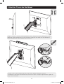
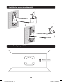
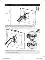
4. Install Decorative Covers
5. Install VESA Plate
Top of Display
14-04-249-93332D.indb 7 5/9/2014 9:37:36 AM

8
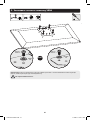
5. Install VESA Plate
Note: Firmly secure the VESA plate to the display using the appropriate screws, washers and spacers
(if necessary).
Do not over-tighten screws.
M4X14 /
M5X14
M4X14 /
M5X14
D5 Washer
D5 Washer
TV
or
14-04-249-93332D.indb 8 5/9/2014 9:37:36 AM

9
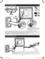
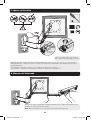
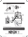
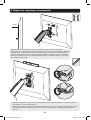
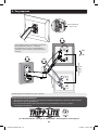
6. Hook the TV onto the Wall Mount
· Position a level on the horizontal and vertical sides of the display and adjust as needed.
· Reattach the lower knobs to the VESA mount (removed in step 1). Using the supplied wrench, tighten all
upper- and lower-knobs.
Using an assistant or mechanical lifting equipment, lift the display with attached VESA plate. Set the
VESA plate’s upper thumbscrews over the top ange of wall plate arm. Make sure the VESA plate’s
lower screws fit inside of the wall plate arm’s lower holes.
4mm
14-04-249-93332D.indb 9 5/9/2014 9:37:36 AM

10
FOLD 3
DUST
C
A
T
CHER
FOLD 3
DUST
C
A
T
CHER
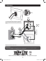
7. Tension Adjustment
8. Cable Management
Tighten the socket screw if the arm
assembly’s joints make popping sounds
during adjustment.
Keep the wall mount arm level during tension adjustment. You may need to slightly loosen or tighten the
adjustment screw using the provided Hex Keys depending on the weight of display installed.
If display settles on its own, rotate adjustment screw towards the “+” symbol.
If display rises on its own, rotate adjustment screw towards the “-” symbol.
6mm Hex
Key
Connect the cables to the display, and press cable cover inward to route the cables
through the space.
Note: Leave slack in cable for cantilever arm movement.
14-04-249-93332D.indb 10 5/9/2014 9:37:41 AM

11
FOLD 3
DUST
C
A
T
CHER
9. Adjustment
To correct the tilting angle, tighten the adjustment
screws using the provided Hex Key (or tighten the
knob).
Adjust to the desired location or tilt.
180°
+15°
-15°
180°
180°
+2° -2°
4mm
Hex Key
Max 335mm (13”)
Height Adjustment
Maintenance
• Check that the bracket is secure and safe to use at regular intervals (at least every three months).
• Please visit www.tripplite.com/support if you have any questions.
1111 W. 35th Street, Chicago, IL 60609 USA • www.tripplite.com/support
14-04-249-93332D.indb 11 5/9/2014 9:37:44 AM

12
Manual del Propietario
Instalación en Pared de
Soporte de Movimiento
Completo para Pantalla Plana
MODELO: DWM1327SP
PRECAUCIÓN: NO EXCEDA LA CAPACIDAD MÁXIMA DE CARGA INDICADA. ¡PUEDE
OCURRIR UNA LESIÓN SEVERA O DAÑO A LA PROPIEDAD!
1111 W. 35th Street, Chicago, IL 60609 USA • www.tripplite.com/support
Copyright © 2014 Tripp Lite. Todos los derechos reservados.
75x75
100x100
13 - 27 pulg.
15 kg
(33 lbs)
English 1 • Français 23 • Русский 34 • Deutsch 45
14-04-249-93332D.indb 12 5/9/2014 9:37:46 AM

13
NOTA: Lea completo el manual de instrucciones antes de iniciar la instalación y ensamble.
Garantía
ADVERTENCIA
• No inicie la instalación hasta que haya leído y entendido las instrucciones y
advertencias contenidas en este manual. Si tiene algunas preguntas con respecto
a alguna de las instrucciones o advertencias, visite por favor
www.tripplite.com/support.
• El soporte de instalación fue diseñado para instalarse y usarse SOLAMENTE como
se especifica en este manual. La instalación incorrecta de este producto puede
causar daños o lesiones severas.
• Este producto debe ser instalado únicamente por alguien con una buena
habilidad mecánica, experiencia básica de construcción y un entendimiento
completo de este manual de instrucciones.
• Cerciórese que la supercie de instalación pueda soportar con seguridad la carga
combinada de todo el hardware y componentes instalados.
• Si se instala en paredes con entramados de madera, cerciórese que los
tornillos de instalación estén anclados en el centro de los montantes. Es muy
recomendable el uso de un detector de montantes.
• Utilice siempre un ayudante o equipo de elevación mecánico para levantar y
colocar el equipo con seguridad.
• A priete los tornillos rmemente pero no en exceso. Apretar excesivamente los
tornillos puede dañar los componentes, reduciendo grandemente su capacidad
de soporte.
• Este producto está diseñado para usarse sólo en interiores. El utilizar este
producto en exteriores podría conducir a fallas del producto y lesiones personales.
Garantía Limitada por 5 Años
El vendedor garantiza este producto, si se usa de acuerdo con todas las instrucciones aplicables, de que está
libre de defectos en material y mano de obra por un período de 5 años a partir de la fecha de compra inicial. Si
el producto prueba ser defectuoso en material o mano de obra dentro de ese período, el vendedor reparará o
reemplazará el producto a su entera discreción.
ESTA GARANTÍA NO APLICA AL DESGASTE NORMAL O A DAÑOS RESULTANTES DE ACCIDENTES, MAL USO,
ABUSO O NEGLIGENCIA. EL VENDEDOR NO OTORGA GARANTÍAS EXPRESAS DISTINTAS DE LA ESTIPULADA AQUÍ.
EXCEPTO A LA EXTENSIÓN PROHIBIDA POR LA LEY APLICABLE, TODAS LAS GARANTÍAS IMPLÍCITAS, INCLUYENDO
TODAS LAS GARANTÍAS DE COMERCIALIZACIÓN O IDONEIDAD, ESTÁN LIMITADAS EN DURACIÓN AL PERÍODO
DE GARANTÍA ESTABLECIDO; Y ESTA GARANTÍA EXCLUYE EXPRESAMENTE TODOS LOS DAÑOS INCIDENTALES Y
CONSECUENCIALES. (Algunos estados no permiten limitaciones en cuanto al período de duración de una garantía
y algunos estados no permiten la exclusión de limitación de daños incidentales o consecuenciales, de modo que
las limitaciones anteriores pueden no aplicar para usted. Esta garantía le otorga derechos legales especícos y
usted puede tener otros derechos que pueden variar de una jurisdicción a otra).
ADVERTENCIA: Antes de usarlo, cada usuario debe debe tener cuidado al determinar si este dispositivo es
adecuado o seguro para el uso previsto. Ya que las aplicaciones individuales están sujetas a gran variación, el
fabricante no garantiza la adecuación de estos dispositivos para alguna aplicación especíca.
Tripp Lite tiene una política de mejora continua. Las especicaciones están sujetas a cambio sin previo aviso.
14-04-249-93332D.indb 13 5/9/2014 9:37:46 AM

14
Accesorios y Partes Incluidas en el Empaque
IMPORTANTE: Asegúrese antes de instalar, de haber recibido todas las partes de acuerdo a la lista de
comprobación de componentes. Si faltase cualquier parte o estuviese dañada, visite
www.tripplite.com/support para solicitar servicio.
DWM1327SP
Llave Hexagonal de
4 mm (x1)
Llave (x1)
Llave Hexagonal de
6 mm (x1)
Tornillo de Anclaje (x3) Ancla para Concreto (x3)
Paquete M
Paquete W
D5 Arandela (x4)M4X14 (x4) M5X14 (x4)
14-04-249-93332D.indb 14 5/9/2014 9:37:46 AM

15
1. Separe la Placa VESA del Montaje para Pared
2. Retire las Cubiertas Decorativas
• Usando la llave suministrada, aoje las dos
perillas superiores
• Retire ambas perillas inferiores
Retire la placa VESA.
D
14-04-249-93332D.indb 15 5/9/2014 9:37:46 AM

16
3a. Instalación en Pared con Entramado de Madera
3
Marque la posición exacta de
los oricios de instalación
Atornille el
soporte de pared
a la pared
Barrene los
oricios piloto
ADVERTENCIA
• Cerciórese que los tornillos de instalación estén anclados en el centro de los
montantes. Es muy recomendable usar un detector de montantes.
• Los instaladores son responsables de proporcionar los accesorios para otros tipos
de soluciones de instalación.
• Los instaladores deben vericar que la supercie de apoyo soporte con seguridad la
carga combinada del equipo y los accesorios y componentes agregados.
Localice una posición del travesaño de madera
para la instalación del soporte de pared
1
2
Tornillo de Anclaje
14-04-249-93332D.indb 16 5/9/2014 9:37:47 AM

17
3b. Instalación sobre Ladrillos Sólidos o Bloques de Concreto
ADVERTENCIA
• Al instalar soportes de pared en una unidad de mampostería de concreto (conocida
también como bloques de concreto), verique que el espesor real del concreto
sea de al menos 35 mm (1-3/8”) a n de sujetar los anclajes para concreto. ¡No
taladre en las uniones de argamasa! Asegúrese de instalar el soporte de pared con
las anclas para concreto tornillos de anclaje incluidos en las secciones sólidas de
los bloques. Las secciones sólidas pueden encontrarse generalmente a 25 mm (1”)
hacia el centro del bloque en cada extremo. Se sugiere utilizar un taladro eléctrico a
baja velocidad para barrenar el oricio en vez de un rotomartillo para evitar rotura de
la parte posterior del orificio al entrar en una sección hueca.
• Los instaladores deben vericar que la supercie de apoyo soporte con seguridad la
carga combinada del equipo y los accesorios y componentes agregados.
Atornille el
soporte de pared
en la pared
Barrene los
oricios piloto
2
Encuentre y marque la
posición exacta de los
oricios de instalación
1
Ancla para Concreto
Tornillo de Anclaje
14-04-249-93332D.indb 17 5/9/2014 9:37:48 AM

18
4. Instale las Cubiertas Decorativas
5. Instale la Placa VESA
Parte superior de la Pantalla
14-04-249-93332D.indb 18 5/9/2014 9:37:49 AM

19
5. Instale la Placa VESA
Nota: Asegure firmemente la placa VESA a la pantalla usando los tornillos, arandelas y espaciadores
apropiados (si fuera necesario).
No apriete excesivamente los tornillos.
o
M4X14 /
M5X14
M4X14 /
M5X14
D5
Arandela
D5
Arandela
TV
14-04-249-93332D.indb 19 5/9/2014 9:37:49 AM

20
6. Cuelgue la TV sobre el Soporte de Pared
• Coloque un nivel en los lados horizontal y vertical de la pantalla y ajuste según sea necesario.
• Reinstale las perillas inferiores al soporte VESA (retirados en el paso 1). Usando la llave suministrada,
apriete todas las perillas superiores e inferiores.
Usando un ayudante o equipo de elevación mecánico, levante la pantalla con la placa VESA
acoplada. Coloque los tornillos de mariposa superiores de la placa VESA sobre la brida superior
del brazo de la placa de pared. Cerciórese de que los tornillos inferiores de la placa VESA
ajusten dentro del oricio inferior del brazo de la placa de pared.
4mm
14-04-249-93332D.indb 20 5/9/2014 9:37:49 AM
La page charge ...
La page charge ...
La page charge ...
La page charge ...
La page charge ...
La page charge ...
La page charge ...
La page charge ...
La page charge ...
La page charge ...
La page charge ...
La page charge ...
La page charge ...
La page charge ...
La page charge ...
La page charge ...
La page charge ...
La page charge ...
La page charge ...
La page charge ...
La page charge ...
La page charge ...
La page charge ...
La page charge ...
La page charge ...
La page charge ...
La page charge ...
La page charge ...
La page charge ...
La page charge ...
La page charge ...
La page charge ...
La page charge ...
La page charge ...
La page charge ...
La page charge ...
-
 1
1
-
 2
2
-
 3
3
-
 4
4
-
 5
5
-
 6
6
-
 7
7
-
 8
8
-
 9
9
-
 10
10
-
 11
11
-
 12
12
-
 13
13
-
 14
14
-
 15
15
-
 16
16
-
 17
17
-
 18
18
-
 19
19
-
 20
20
-
 21
21
-
 22
22
-
 23
23
-
 24
24
-
 25
25
-
 26
26
-
 27
27
-
 28
28
-
 29
29
-
 30
30
-
 31
31
-
 32
32
-
 33
33
-
 34
34
-
 35
35
-
 36
36
-
 37
37
-
 38
38
-
 39
39
-
 40
40
-
 41
41
-
 42
42
-
 43
43
-
 44
44
-
 45
45
-
 46
46
-
 47
47
-
 48
48
-
 49
49
-
 50
50
-
 51
51
-
 52
52
-
 53
53
-
 54
54
-
 55
55
-
 56
56


Tripp Lite Full Motion Flat Screen Wall Mount Le manuel du propriétaire
- Catégorie
- Supports muraux à panneau plat
- Taper
- Le manuel du propriétaire
dans d''autres langues
Documents connexes
-
Tripp Lite DWM1742MA Display Mount Le manuel du propriétaire
-
-
-
Tripp Lite DWM1742MN Le manuel du propriétaire
-
-
-
-
-
-
Tripp Lite DDR1026SD Le manuel du propriétaire