
MKS Type T3PIA
Pendulum Valve
With Analog/TTL Interface
Instruction Manual
Six Shattuck Road
Andover, MA 01810-2449
Main: 978.975.2350 137363-P1
www.mksinst.com Analog/TTL Interface
Rev C

WARRANTY
Type T3PIA Pendulum Valve with Analog/TTL Interface
MKS Instruments, Inc. (MKS) warrants that for one (1) year from the date of shipment the equipment
described above (the “equipment”) manufactured by MKS shall be free from defects in materials and
workmanship.
For the period commencing with the date of shipment of this equipment and ending one (1) year later, MKS
will, at its option, either repair or replace any part which is defective in materials or workmanship without
charge to the purchaser. The foregoing shall constitute the exclusive and sole remedy of the purchaser for any
breach of MKS of this warranty.
The purchaser, before returning any equipment covered by this warranty, which is asserted to be defective by
the purchaser, shall make specific written arrangements with respect to the responsibility for shipping the
equipment and handling any other incidental charges with the MKS Sales Representative or distributor from
which the equipment was purchased or, in the case of a direct purchase from MKS, with the MKS home
office in Andover, Massachusetts, USA.
This warranty does not apply to any equipment which has not been installed and used in accordance with the
specifications recommended by MKS for the proper and normal use of the equipment. MKS shall not be
liable under any circumstances for indirect, special, consequential, or incidental damages in connection with,
or arising out of, the sale, performance, or use of the equipment covered by this warranty.
MKS recommends that all MKS pressure and flow products be calibrated periodically (typically) every 6 to
12 months) to ensure accurate readings. When a product is returned to MKS for this periodic re-calibration it
is considered normal preventative maintenance not covered by any warranty.
THIS WARRANTY IS IN LIEU OF ALL OTHER RELEVANT WARRANTIES, EXPRESSED OR
IMPLIED, INCLUDING THE IMPLIED WARRANTY OF MERCHANTABILITY AND THE IMPLIED
WARRANTY OF FITNESS FOR A PARTICULAR PURPOSE, AND ANY WARRANTY AGAINST
INFRINGEMENT OF ANY PATENT.

MKS Type T3PIA
Pendulum Valve
With Analog/TTL Interface

Copyright © 2009 by MKS Instruments, Inc.
All rights reserved. No part of this work may be reproduced or transmitted in any form or by any means,
electronic or mechanical, including photocopying and recording, or by any information storage or retrieval
system, except as may be expressly permitted in writing by MKS Instruments, Inc.
Printed in the United States of America
US Patent 6,089,537 and other Patents Pending
DeviceNet™ is a trademark of Open DeviceNet Vendor Association, Inc., Coral Springs, FL.
SEMI
®
is a registered trademark of Semiconductor Equipment and Materials International, Mountain View,
CA.
Swagelok
®
and VCR
®
are registered trademark of Swagelok Marketing Co., Solon, OH.
Firmware version: 01.02

v
Table of Contents
Valve Safety Information..................................................................................................................................1
Symbols Used in This Instruction Manual ....................................................................................................................1
Symbols Found on the Unit...........................................................................................................................................1
Safety Procedures and Precautions................................................................................................................................1
Sicherheitshinweise für das Ventil....................................................................................................................3
In dieser Betriebsanleitung vorkommende Symbole.....................................................................................................3
Erklärung der am Gerät angebrachten Symbole............................................................................................................3
Sicherheitsvorschriften und Vorsichtsmaßnahmen .......................................................................................................3
Informations de sécurité relatives au manomètre...........................................................................................5
Symboles utilisés dans ce manuel d’utilisation.............................................................................................................5
Symboles figurant sur l’unité ........................................................................................................................................5
Mesures de sécurité et précautions................................................................................................................................5
Medidas de seguridad del manómetro.............................................................................................................7
Símbolos usados en este manual de instrucciones.........................................................................................................7
Símbolos hallados en la unidad.....................................................................................................................................7
Procedimientos y precauciones de seguridad................................................................................................................7
Chapter One: General Information ................................................................................................................9
Introduction...................................................................................................................................................................9
How This Manual is Organized...................................................................................................................................10
Customer Support........................................................................................................................................................10
Chapter Two: Installation..............................................................................................................................11
Unpacking the Type T3P Unit.....................................................................................................................................11
Interface Cables...........................................................................................................................................................11
Product Location and Requirements............................................................................................................................13
Setup............................................................................................................................................................................14
Setup Procedures.........................................................................................................................................................17
Electrical Information..................................................................................................................................................18
Startup .........................................................................................................................................................................23
Chapter Three: Product Overview................................................................................................................25
General Information ....................................................................................................................................................25
Control Mode ..............................................................................................................................................................25
Trip Points...................................................................................................................................................................30
Top Panel Components................................................................................................................................................32
Labels..........................................................................................................................................................................34
Chapter Four: Analog/TTL Operation.........................................................................................................35
General Information ....................................................................................................................................................35
Selecting the Digital Input Functions..........................................................................................................................35
Setting the Analog Set Point Inputs.............................................................................................................................36
Selecting the Digital Output Functions........................................................................................................................36
Using RS-232 Commands with an Analog T3P..........................................................................................................36
Chapter Five: Maintenance and Troubleshooting.......................................................................................37
General Information ....................................................................................................................................................37
Maintenance ................................................................................................................................................................37

vi
Preventive Maintenance ..............................................................................................................................................37
Troubleshooting...........................................................................................................................................................45
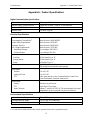
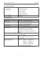
Appendix A: Product Specifications.............................................................................................................47
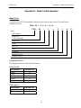
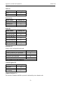
Appendix B: Model Code Explanation.........................................................................................................49
Model Code.................................................................................................................................................................49
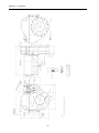
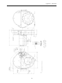
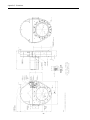
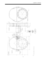
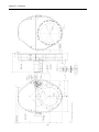
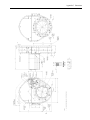
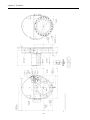
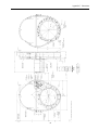
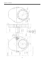
Appendix C: Dimensions ...............................................................................................................................51
Index.................................................................................................................................................................61
List of Figures
Figure 1: Preferred Method To Connect an Overall Metal Braided Shielded Cable........................................12
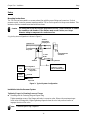
Figure 2: Alternate Method To Connect an Overall Metal Braided Shielded Cable........................................13
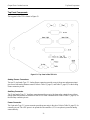
Figure 3: Typical System Configuration..........................................................................................................14
Figure 4: Top Panel of the T3P Unit................................................................................................................ 19
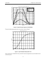
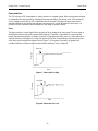
Figure 5: Typical Pressure Response in LEARN Mode...................................................................................27
Figure 6. Typical Chamber Pump Speed Curve...............................................................................................27
Figure 7: Phase Set Too High...........................................................................................................................28
Figure 8: Phase Set Too Low ...........................................................................................................................28
Figure 9: Gain Set Too High............................................................................................................................29
Figure 10: Gain Set Too Low...........................................................................................................................29
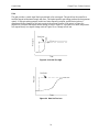
Figure 11: Trip Point Direction Set Low..........................................................................................................31
Figure 12: Trip Point Direction Set High.........................................................................................................31
Figure 13: Top Panel of the T3P Unit.............................................................................................................. 32
Figure 14: Pump Label.....................................................................................................................................34
Figure 15: Serial Number Label.......................................................................................................................34
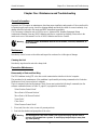
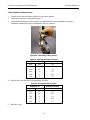
Figure 16: Four (4) Valve Cover Screws..........................................................................................................38
Figure 17: Gate Bolt.........................................................................................................................................38
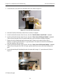
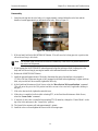
Figure 18: Handle.............................................................................................................................................39
Figure 19: Seal Ring Removal .........................................................................................................................39
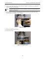
Figure 20: Lubricating O-Ring Groove............................................................................................................40
Figure 21: Seal Ring in Valve Body................................................................................................................. 41
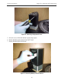
Figure 22: Removing Phillips Head Screws..................................................................................................... 43
Figure 23: Removing Battery Pack from Device .............................................................................................43
Figure 24: Installing the New Battery Pack......................................................................................................44

vii
List of Tables
Table 1: Definition of Symbols Found on the Unit.............................................................................................1
Tabelle 2: Bedeutung der am Gerät angebrachten Symbole...............................................................................3
Tableau 3: Définition des symboles sur l’unité ..................................................................................................5
Tabla 4: Definición de los símbolos hallados en la unidad.................................................................................7
Table 5: Definitions ............................................................................................................................................9
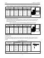
Table 6: Maximum Torque Levels When Mounting With the Centering Ring and Spacer Ring.....................15
Table 7: Maximum Torque Levels When Mounting with the O-Ring in Groove ............................................15
Table 8: Admissible Forces ..............................................................................................................................15
Table 9: Mounting Screw Length .....................................................................................................................16
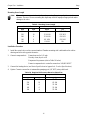
Table 10: Required Air Pressure Based on Valve Size.....................................................................................16
Table 11: Auxiliary Connector Pin Out............................................................................................................20
Table 12: Analog Sensor 1 (High) Connector Pin Out.....................................................................................21
Table 13: Analog Sensor 2 (Low) Connector Pin Out......................................................................................22
Table 14: Power Connector Pin Out.................................................................................................................22
Table 15: Differential Pressure.........................................................................................................................23
Table 16: Position Status LED Indicators.........................................................................................................33
Table 17: Pressure Status LED Indicators ........................................................................................................33
Table 18: Digital Input Functions.....................................................................................................................35
Table 19: Digital Output Functions ..................................................................................................................36
Table 20: Seal Ring Quantity of Grease ...........................................................................................................40
Table 21: O-Ring Quantity of Grease...............................................................................................................40
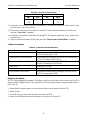
Table 22: Valve Cover Screw Torque...............................................................................................................42
Table 23: Software Command Reference.........................................................................................................42

viii
This page intentionally left blank.

Valve Safety Information
1
Valve Safety Information
Symbols Used in This Instruction Manual
Definitions of WARNING, CAUTION, and NOTE messages used throughout the manual are:
Warning
The WARNING sign denotes a hazard. It calls attention to a procedure, practice,
condition, or the like, which, if not correctly performed or adhered to, could result
in injury to personnel.
Caution
The CAUTION sign denotes a hazard. It calls attention to an operating procedure,
practice, or the like, which, if not correctly performed or adhered to, could result in
damage to or destruction of all or part of the product.
Note
The NOTE sign denotes important information. It calls attention to a procedure, practice,
condition, or the like, which is essential to highlight.
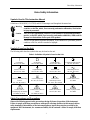
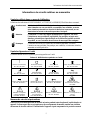
Symbols Found on the Unit
The following table describes symbols that may be found on the unit.
Table 1: Definition of Symbols Found on the Unit
|
On (Supply)
IEC 417, No. 5007
Off (Supply)
IEC 417, No. 5008
Earth (ground)
IEC 417, No. 5017
Protective Earth (ground)
IEC 417, No. 5019
Frame or Chassis
IEC 417, No. 5020
Equipotentiality
IEC 417, No. 5021
Direct Current
IEC 417, No. 5031
Alternating Current
IEC 417, No. 5032
Both Direct and Alternating
Current
IEC 417, No. 5033-a
Class II Equipment
IEC 417, No. 5172-a
Three Phase
Alternating Current
IEC 617-2, No. 020206
Caution, Hand Crush
ISO 3864
Caution (refer to
accompanying documents)
ISO 3864, No. B.3.1
Caution, Risk of Electric
Shock
ISO 3864, No. B.3.6
Caution, Hot Surface
IEC 417, No. 5041
Caution, Spring Loaded
ISO 3864
Safety Procedures and Precautions
Observe the following general safety precautions during all phases of operation of this instrument.
Failure to comply with these precautions or with specific warnings elsewhere in this manual violates
safety standards of intended use of the instrument and may impair the protection provided by the
equipment. MKS Instruments, Inc. assumes no liability for the customer’s failure to comply with these
requirements.

Valve Safety Information
2
Warning
Moving parts in the valve create a risk of personal injury until the valve is securely
incorporated into a system. To avoid injury, keep all body parts away from any
valve opening.
1.
Do not insert objects into openings where contact with moving parts is
possible.
2.
Isolate the valve from any electrical or pneumatic power supply before
handling the valve.
DO NOT SUBSTITUTE PARTS OR MODIFY VALVE
Do not install substitute parts or perform any unauthorized modification to the valve. Return the valve to an MKS
Calibration and Service Center for service and repair to ensure that all safety features are maintained.
SERVICE BY QUALIFIED PERSONNEL ONLY
Operating personnel must not attempt component replacement and internal adjustments. Qualified service personnel
must perform any service only.
USE CAUTION WHEN OPERATING WITH HAZARDOUS MATERIALS
If hazardous materials are used, observe the proper safety precautions, completely purge the valve when necessary, and
ensure that the material used is compatible with the wetted materials in this product, including any sealing materials.
PURGE THE VALVE
After installing the unit, or before removing it from a system, purge the unit completely with a clean, dry gas to eliminate
all traces of the previously used flow material.
USE PROPER PROCEDURES WHEN PURGING
This valve must be purged under a ventilation hood and gloves must be worn for protection.
DO NOT OPERATE IN AN EXPLOSIVE ENVIRONMENT
To avoid explosion, do not operate this product in an explosive environment unless it has been specifically certified for
such operation.
USE PROPER FITTINGS AND TIGHTENING PROCEDURES
All valve fittings must be consistent with valve specifications and compatible with the intended use of the valve.
Assemble and tighten fittings according to manufacturer’s directions.
CHECK FOR LEAK-TIGHT FITTINGS
Carefully check all vacuum component connections to ensure leak-tight installation.
OPERATE AT SAFE INLET PRESSURES
Never operate the valve at pressures higher than the rated maximum pressure (refer to the product specifications for the
maximum allowable pressure).
INSTALL A SUITABLE BURST DISC
When operating from a pressurized gas source, install a suitable burst disc in the vacuum system to prevent system
explosion should the system pressure rise.
KEEP THE UNIT FREE OF CONTAMINANTS
Do not allow contaminants to enter the unit before or during use. Contamination such as dust, dirt, lint, glass chips, and
metal chips may permanently damage the unit or contaminate the process.
KEEP AWAY FROM VALVE OPENING
Keep fingers, other body parts, and other materials away from the valve opening when the valve is in operation.

Sicherheitshinweise für das Ventil
3
Sicherheitshinweise für das Ventil
In dieser Betriebsanleitung vorkommende Symbole
Bedeutung der mit WARNUNG!, VORSICHT! und HINWEIS gekennzeichneten Absätze in dieser
Betriebsanleitung.
Warnung!
Das Symbol WARNUNG! weist auf eine Gefahr für das Bedienpersonal hin. Es
macht auf einen Arbeitsablauf, eine Arbeitsweise, einen Zustand oder eine
sonstige Gegebenheit aufmerksam, deren unsachgemäße Ausführung bzw.
ungenügende Berücksichtigung zu Verletzungen führen kann.
Vorsicht!
Das Symbol VORSICHT! weist auf eine Gefahr für das Gerät hin. Es macht auf
einen Bedienungsablauf, eine Arbeitsweise oder eine sonstige Gegebenheit
aufmerksam, deren unsachgemäße Ausführung bzw. ungenügende
Berücksichtigung zu einer Beschädigung oder Zerstörung des Gerätes oder von
Teilen des Gerätes führen kann.
Hinweis
Das Symbol HINWEIS macht auf wichtige Informationen bezüglich eines
Arbeitsablaufs, einer Arbeitsweise, eines Zustands oder einer sonstige Gegebenheit
aufmerksam.
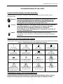
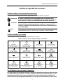
Erklärung der am Gerät angebrachten Symbole
Nachstehender Tabelle sind die Bedeutungen der Symbole zu entnehmen, die am Gerät angebracht sein können.
Tabelle 2: Bedeutung der am Gerät angebrachten Symbole
|
Ein (Energie)
IEC 417, No.5007
Aus (Energie)
IEC 417, No.5008
Erdanschluss
IEC 417, No.5017
Schutzleiteranschluss
IEC 417, No.5019
Masseanschluss
IEC 417, No.5020
Aquipotentialanschluss
IEC 417, No.5021
Gleichstrom
IEC 417, No.5031
Wechselstrom
IEC 417, No.5032
Gleich- oder Wechselstrom
IEC 417, No.5033-a
Durchgängige doppelte
oder verstärkte Isolierung
IEC 417, No.5172-a
Dreileiter-Wechselstrom
(Drehstrom)
IEC 617-2, No.020206
Vorsicht: Quetschgefahr für
die Hand
ISO 3864
Warnung vor einer
Gefahrenstelle (Achtung,
Dokumentation beachten)
ISO 3864, No.B.3.1
Warnung vor gefährlicher
elektrischer Spannung
ISO 3864, No.B.3.6
Höhere Temperatur an
leicht zugänglichen Teilen
IEC 417, No.5041
Vorsicht: Federspannung
ISO 3864
Sicherheitsvorschriften und Vorsichtsmaßnahmen
Folgende allgemeine Sicherheitsvorschriften sind während allen Betriebsphasen dieses Gerätes zu
befolgen. Eine Missachtung der Sicherheitsvorschriften und sonstiger Warnhinweise in dieser

Sicherheitshinweise für das Ventil
4
Betriebsanleitung verletzt die für dieses Gerät und seine Bedienung geltenden Sicherheitsstandards,
und kann die Schutzvorrichtungen an diesem Gerät wirkungslos machen. MKS Instruments, Inc.
haftet nicht für Missachtung dieser Sicherheitsvorschriften seitens des Kunden.
Warnung
Solange das Ventil nicht fest in ein System eingebaut ist, besteht
Verletzungsgefahr aufgrund von beweglichen Teilen. Daher Finger und andere
Körperteile unbedingt von allen Ventilöffnungen fernhalten.
1. Niemals Fremdkörper in Öffnungen einführen, in denen ein Kontakt mit
beweglichen Teilen möglich ist.
2. Das Ventil vor dem Hantieren stets von allen elektrischen und pneumatischen
Kraftquellen trennen.
Niemals Teile austauschen oder Änderungen am Ventil vornehmen!
Ersetzen Sie keine Teile mit baugleichen oder ähnlichen Teilen, und nehmen Sie keine eigenmächtigen Änderungen am
Ventil vor. Schicken Sie das Ventil zwecks Wartung und Reparatur an den MKS-Kalibrierungs- und -Kundendienst ein.
Nur so wird sichergestellt, daß alle Schutzvorrichtungen voll funktionsfähig bleiben.
Wartung nur durch qualifizierte Fachleute!
Das Auswechseln von Komponenten und das Vornehmen von internen Einstellungen darf nur von qualifizierten
Fachleuten durchgeführt werden, niemals vom Bedienpersonal.
Vorsicht beim Arbeiten mit gefährlichen Stoffen!
Wenn gefährliche Stoffe verwendet werden, muß der Bediener die entsprechenden Sicherheitsvorschriften genauestens
einhalten, das Ventil, falls erforderlich, vollständig spülen, sowie sicherstellen, daß der Gefahrstoff die von ihm
benetzten, im Ventil verwendeten Materialien, insbesondere Dichtungen, nicht angreift.
Spülen des Ventils mit Gas!
Nach dem Installieren oder vor dem Ausbau aus einem System muß das Ventil unter Einsatz eines reinen Trockengases
vollständig gespült werden, um alle Rückstände des Vorgängermediums zu entfernen.
Anweisungen zum Spülen des Ventils!
Das Ventil darf nur unter einer Ablufthaube gespült werden. Schutzhandschuhe sind zu tragen.
Nicht zusammmen mit explosiven Stoffen, Gasen oder Dämpfen benutzen!
Um der Gefahr einer Explosion vorzubeugen, darf dieses Produkt niemals zusammen mit explosiven Stoffe aller Art
eingesetzt werden, sofern es nicht ausdrücklich für diesen Zweck zugelassen ist.
Anweisungen zum Installieren der Armaturen!
Alle Ventilanschlußstücke und Armaturenteile müssen mit den Ventilspezifikationen übereinstimmen, und mit dem
geplanten Einsatz des Ventils kompatibel sein. Der Einbau, insbesondere das Anziehen und Abdichten, muß gemäß den
Anweisungen des Herstellers vorgenommen werden.
Ventil auf Undichtigkeiten prüfen!
Überprüfen Sie sorgfältig alle Verbindungen auf undichte Stellen.
Nur unter zulässigen Anschlußdrücken betreiben!
Betreiben Sie das Ventil niemals unter Drücken, die den maximal zulässigen Druck (siehe Produktspezifikationen)
übersteigen.
Geeignete Berstscheibe installieren!
Wenn mit einer unter Druck stehenden Gasquelle gearbeitet wird, sollte eine geeignete Berstscheibe in das
Vakuumsystem installiert werden, um eine Explosionsgefahr aufgrund von steigendem Systemdruck zu vermeiden.
Verunreinigungen vermeiden!
Stellen Sie sicher, daß Verunreinigungen jeglicher Art weder vor dem Einsatz noch während des Betriebs in das Innere
gelangen können. Staub- und Schmutzpartikel, Glassplitter oder Metallspäne können das Produkt dauerhaft beschädigen
oder Prozeß und Meßwerte verfälschen.
Hände weg von der Ventilöffnung!
Körperteile, insbesondere Finger, sowie Fremdobjekte während des Betriebes von der Ventilöffnung fernhalten.

Informations de sécurité relatives au manomètre
5
Informations de sécurité relatives au manomètre
Symboles utilisés dans ce manuel d’utilisation
Définitions des indications AVERTISSEMENT, ATTENTION, et REMARQUE utilisées dans ce manuel.
Avertissement
L’indication AVERTISSEMENT signale un danger pour le personnel. Elle
attire l’attention sur une procédure, une pratique, une condition, ou toute
autre situation présentant un risque d’accident pour le personnel, en cas
d’exécution incorrecte ou de non-respect des consignes.
Attention
L’indication ATTENTION signale un danger pour l’appareil. Elle attire
l’attention sur une procédure d’exploitation, une pratique, ou toute autre
situation, présentant un risque de dégât ou de destruction partielle ou totale
du produit, en cas d’exécution incorrecte ou de non-respect des consignes.
Remarque
L’indication REMARQUE signale une information importante. Elle attire
l’attention sur une procédure, une pratique, une condition, ou toute autre situation,
présentant un intérêt particulier.
Symboles figurant sur l’unité
Le tableau suivant décrit les symboles pouvant apparaître sur l’unité.
Tableau 3: Définition des symboles sur l’unité
|
Marche (sous tension)
IEC 417, No.5007
Arrêt (hors tension)
IEC 417, No.5008
Terre (masse)
IEC 417, No.5017
Terre de protection (masse)
IEC 417, No.5019
Masse
IEC 417, No.5020
Equipotentialité
IEC 417, No.5021
Courant continu
IEC 417, No.5031
Courant alternatif
IEC 417, No.5032
Courant continu et alternatif
IEC 417, No.5033-a
Matériel de classe II
IEC 417, No.5172-a
Courant alternatif triphasé
IEC 617-2, No.020206
Attention : Danger
d’écrasement de la main
ISO 3864
Attention : se reporter
à la documentation
ISO 3864, No.B.3.1
Attention : risque de
choc électrique
ISO 3864, No.B.3.6
Attention : surface brûlante
IEC 417, No.5041
Attention : Ce dispositif est à
ressort
ISO 3864
Mesures de sécurité et précautions
Observer les précautions générales de sécurité suivantes pendant toutes les phases d’exploitation de cet
appareil. Le non-respect des ces précautions ou des avertissements du manuel constitue une violation
des normes de sécurité relatives à l’utilisation de l’appareil et peut compromettre la protection assurée

Informations de sécurité relatives au manomètre
6
par l’appareil. MKS Instruments, Inc. rejette toute responsabilité en cas de non-respect des consignes
par les clients.
Avertissement
Les pièces mobiles de la valve peuvent être une cause d'accident tant que la
valve n'est pas solidement incorporée dans un système. Pour éviter tout
accident, tenir toute partie du corps à distance de toute ouverture de la valve.
1. Ne pas insérer des objets dans les ouvertures où le contact avec des
pièces mobiles est possible.
2. Isoler la valve de toute source d'alimentation électrique ou pneumatique
pendant la manipulation de la valve.
PAS DE SUBSTITUTION DE PIÈCES OU DE MODIFICATION DE LA VALVE
Ne pas installer des pièces de substitution ou effectuer des modifications non autorisées sur la valve. Renvoyer la valve à
un centre de service et de calibrage MKS pour tout dépannage ou réparation afin de garantir le l'intégrité des dispositifs
de sécurité.
DÉPANNAGE UNIQUEMENT PAR DU PERSONNEL QUALIFIÉ
Le personnel d'exploitation ne doit pas essayer de remplacer des composants ou de faire des réglages internes. Tout
dépannage doit être uniquement effectué par du personnel qualifié.
PRÉCAUTION EN CAS D'UTILISATION AVEC DES PRODUITS DANGEREUX
Si des produits dangereux sont utilisés, prendre les mesures de précaution appropriées, purger complètement la valve
quand cela est nécessaire, et s'assurer que les produits utilisés sont compatibles avec les composants liquides de
l'appareil, y compris les matériaux d'étanchéité.
PURGE DE LA VALVE
Après l'installation de l'unité, ou avant son enlèvement d'un système, purger l'unité complètement avec un gaz propre et
sec afin d'éliminer toute trace du produit de flux utilisé précédemment.
UTILISATION DES PROCÉDURES APPROPRIÉES POUR LA PURGE
Cette valve doit être purgée sous une hotte de ventilation, et il faut porter des gants de protection.
PAS D'EXPLOITATION DANS UN ENVIRONNEMENT EXPLOSIF
Pour éviter toute explosion, ne pas utiliser cet appareil dans un environnement explosif, sauf en cas d'homologation
spécifique pour une telle exploitation.
UTILISATION D'ÉQUIPEMENTS APPROPRIÉS ET PROCÉDURES DE SERRAGE
Tous les équipements de la valve doivent être cohérents avec ses spécifications, et compatibles avec l'utilisation prévue
de la valve. Assembler et serrer les équipements conformément aux directives du fabricant.
VÉRIFICATION DE L'ÉTANCHÉITÉ DES CONNEXIONS
Vérifier attentivement toutes les connexions des composants pour le vide afin de garantir l'étanchéité de l'installation.
EXPLOITATION AVEC DES PRESSIONS D'ENTRÉE NON DANGEREUSES
Ne jamais utiliser la valve avec des pressions supérieures à la pression nominale maximum (se reporter aux
spécifications de l'unité pour la pression maximum admissible).
INSTALLATION D'UN DISQUE D'ÉCHAPPEMENT ADAPTÉ
En cas d'exploitation avec une source de gaz pressurisé, installer un disque d'échappement adapté dans le système à vide
afin d'éviter une explosion du système en cas d'augmentation de la pression.
MAINTIEN DE L'UNITÉ À L'ABRI DES CONTAMINATIONS
Ne pas laisser des produits contaminants pénétrer dans l'unité avant ou pendant l'utilisation. Des produits contaminants
tels que des poussières et des fragments de tissu, de glace et de métal peuvent endommager l'unité d'une manière
permanente ou contaminer le processus.
PRÉCAUTION AVEC L'OUVERTURE DE LA VALVE
Éviter tout contact des mains, toute autre partie du corps, ou tout autre matériel avec l'ouverture de la valve quand celle-
ci est en fonctionnement.

Medidas de seguridad del manómetro
7
Medidas de seguridad del manómetro
Símbolos usados en este manual de instrucciones
Definiciones de los mensajes de advertencia, precaución y de las notas usados en el manual.
Advertencia
El símbolo de advertencia indica la posibilidad de que se produzcan daños
personales. Pone de relieve un procedimiento, práctica, estado, etc. que en caso
de no realizarse o cumplirse correctamente puede causar daños personales.
Precaución
El símbolo de precaución indica la posibilidad de producir daños al equipo.
Pone de relieve un procedimiento operativo, práctica, etc. que en caso de no
realizarse o cumplirse correctamente puede causar daños o la destrucción total
o parcial del equipo.
Nota
El símbolo de notas indica información de importancia. Este símbolo pone de relieve
un procedimiento, práctica o condición cuyo conocimiento es esencial destacar.
Símbolos hallados en la unidad
La tabla siguiente contiene los símbolos que puede hallar en la unidad.
Tabla 4: Definición de los símbolos hallados en la unidad
|
Encendido
(alimentación eléctrica)
IEC 417, N° 5007
Apagado
(alimentación eléctrica)
IEC 417, N° 5008
Puesta a tierra
IEC 417, N° 5017
Protección a tierra
IEC 417, N° 5019
Caja o chasis
IEC 417, N° 5020
Equipotencialidad
IEC 417, N° 5021
Corriente continua
IEC 417, N° 5031
Corriente alterna
IEC 417, N° 5032
Corriente continua y alterna
IEC 417, N° 5033-a
Equipo de clase II
IEC 417, N° 5172-a
Corriente alterna trifásica
IEC 617-2, N° 020206
Precaución. Peligro de
aplastamiento de la mano
ISO 3864
Precaución. Consulte los
documentos adjuntos
ISO 3864, N° B.3.1
Precaución.
Riesgo de descarga eléctrica
ISO 3864, N° B.3.6
Precaución. Superficie
caliente
IEC 417, N° 5041
Precaución. Dispositivo a
presión
ISO 3864
Procedimientos y precauciones de seguridad
Las medidas generales de seguridad descritas a continuación deben observarse durante todas las etapas
de funcionamiento del instrumento. La falta de cumplimiento de dichas medidas de seguridad o de las
advertencias específicas a las que se hace referencia en otras partes de este manual, constituye una
violación de las normas de seguridad establecidas para el uso previsto del instrumento y podría anular

Medidas de seguridad del manómetro
8
la protección proporcionada por el equipo. Si el cliente no cumple dichas precauciones y advertencias,
MKS Instruments, Inc. no asume responsabilidad legal alguna.
Advertencia
Hasta que la válvula sea incorporada en forma segura al sistema, las piezas en
movimiento presentes en la misma pueden causar daños personales. Para
evitarlo, mantenga todo el cuerpo alejado de la abertura de válvula.
1. No introduzca por las aberturas objetos que puedan entrar en contacto con
piezas en movimiento.
2. Antes de tocar la válvula, aíslela de toda fuente de alimentación neumática
o eléctrica.
NO UTILICE PIEZAS NO ORIGINALES O MODIFIQUE LA VÁLVULA
No instale piezas que no sean originales o modifique la válvula sin autorización. Para asegurar el correcto
funcionamiento de todos los dispositivos de seguridad, envíe la válvula al Centro de servicio y calibración de MKS toda
vez que sea necesario efectuar reparaciones o tareas de mantenimiento.
LAS REPARACIONES DEBEN SER EFECTUADAS ÚNICAMENTE POR TÉCNICOS AUTORIZADOS
Los operarios no deben intentar reemplazar los componentes o realizar tareas de ajuste en el interior. Las tareas de
mantenimiento o reparación deben ser realizadas únicamente por personal autorizado.
TENGA CUIDADO CUANDO TRABAJE CON MATERIALES TÓXICOS
Cuando se utilicen materiales tóxicos, los operarios deberán cumplir las medidas de seguridad correspondientes, purgar
totalmente la válvula cuando sea necesario y comprobar que el material utilizado sea compatible con los materiales
humedecidos del instrumento e inclusive, con los materiales de sellado.
PURGUE LA VÁLVULA
Una vez instalada la unidad o antes de retirarla del sistema, purgue completamente la unidad con gas limpio y seco para
eliminar todo resto de la sustancia líquida empleada anteriormente.
USE PROCEDIMIENTOS ADECUADOS PARA REALIZAR LA PURGA
La válvula debe purgarse debajo de una campana de ventilación y deben utilizarse guantes protectores.
NO HAGA FUNCIONAR LA VÁLVULA EN UN AMBIENTE CON RIESGO DE EXPLOSIONES
Para evitar que se produzcan explosiones, no haga funcionar este producto en un ambiente con riesgo de explosiones,
excepto cuando el mismo haya sido certificado específicamente para tal uso.
USE ACCESORIOS ADECUADOS Y REALICE CORRECTAMENTE LOS PROCEDIMIENTOS DE AJUSTE
Todos los accesorios de la válvula deben cumplir las especificaciones de la misma y ser compatibles con el uso que se
debe dar a la válvula. Arme y ajuste los accesorios de acuerdo con las instrucciones del fabricante.
COMPRUEBE QUE LAS CONEXIONES SEAN A PRUEBA DE FUGAS
Inspeccione cuidadosamente las conexiones de los componentes de vacío para comprobar que hayan sido instalados a
prueba de fugas.
HAGA FUNCIONAR LA VÁLVULA CON PRESIONES DE ENTRADA SEGURAS
No haga funcionar nunca la válvula con presiones superiores a la máxima presión nominal (en las especificaciones del
instrumento hallará la presión máxima permitida).
INSTALE UNA CÁPSULA DE SEGURIDAD ADECUADA
Cuando el instrumento funcione con una fuente de gas presurizado, instale una cápsula de seguridad adecuada en el
sistema de vacío para evitar que se produzcan explosiones cuando suba la presión del sistema.
MANTENGA LA UNIDAD LIBRE DE CONTAMINANTES
No permita el ingreso de contaminantes en la unidad antes o durante su uso. Los productos contaminantes tales como
polvo, suciedad, pelusa, lascas de vidrio o virutas de metal pueden dañar irreparablemente la unidad o contaminar el
proceso.
MANTÉNGASE ALEJADO DE LA ABERTURA DE LA VÁLVULA
Cuando la válvula esté funcionando, mantenga los dedos, otras partes del cuerpo y otros materiales alejados de la abertura.

Introduction Chapter One: General Information
9
Chapter One: General Information
Introduction
The MKS Type T3P Throttle Valve is designed for use in downstream pressure control applications.
The T3P unit consists of a throttling isolation valve with an electronic housing attached to the motor plate, a
microprocessor, driver circuits which eliminate the need for a separate controller box, the RS-232 serial
communications interface, and analog outputs that reflect pressure or valve position. The valve is controlled
by using digital values sent through the serial network.
The operation of the controller is based on a digital pressure/position control algorithm that directs the valve
to the proper position for either pressure or position control. The pressure or position setpoint is sent as a
digital serial command. The T3P unit reads the pressure signal used for control applications directly from an
MKS Baratron pressure transducer. All of the unit’s operational settings are controlled using the serial
communication protocol.
When the T3P controller is turned off or experiences an unexpected power loss, all calibration constants are
saved in non-volatile memory.
Protection from RF interference and noisy electrical environments is increased by the use of a metal case, by
internal design elements, and by the use of surge and ESD suppression networks and RFI filtering on all
inputs and outputs. The T3P unit meets the testing standards required for the European CE Mark when used
with an overall metal braided shielded cable, properly grounded at both ends.
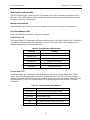
Definitions
Table 5: Definitions
Term Description
Full Scale (FS) Range The defined 100% value of an attribute, in its assigned units
Sccm Standard cubic centimeters per minute
Setpoint The pressure value to which the device is controlling the flow of gas
Slm Standard liters per minute
Trip Point An alarm or warning level

Chapter One: General Information How This Manual is Organized
10
How This Manual is Organized
This manual is designed to provide instructions on how to set up, install, and operate a Type T3P unit.
Before installing your Type T3P unit in a system and/or operating it, carefully read and familiarize
yourself with all precautionary notes in the Safety Messages and Procedures section at the front of this
manual. In addition, observe and obey all
WARNING and CAUTION notes provided throughout the
manual.
Chapter One, General Information, (this chapter) introduces the product and describes the organization of the
manual.
Chapter Two, Installation, explains the environmental requirements and describes how to mount the
instrument in your system. This chapter provides setup and installation procedures.
Chapter Three, Product Overview, gives a brief description of the instrument and its functionality.
Chapter Four, Analog/TTL Operation, describes how to operate the instrument, including how to select the
digital input functions, how to set the analog set point inputs, how to select the digital output functions, and
how to use RS-232 commands with an analog T3P/B.
Chapter Five, Maintenance and Troubleshooting, lists any maintenance required to keep the instrument in
good working condition, and provides a checklist for reference should the instrument malfunction.
Appendix A, Product Specifications, lists the specifications of the instrument.
Appendix B, Model Code Explanation, describes the model code used to order the instrument.
Appendix C, Dimensions, contains line drawings of the various sizes of the T3P Analog/TTL.
Customer Support
Standard maintenance and repair services are available at all of our regional MKS Calibration and Service
Centers, listed on the back cover. In addition, MKS accepts the instruments of other manufacturers for
recalibration using the Primary and Transfer Standard calibration equipment located at all of our regional
service centers.
Should any difficulties arise in the use of your Type T3P instrument, or to obtain information about
companion products MKS offers, contact any authorized MKS Calibration and Service Center. If it is
necessary to return the instrument to MKS, please obtain an ERA Number (Equipment Return Authorization
Number) from the MKS Calibration and Service Center before shipping. The ERA Number expedites
handling and ensures proper servicing of your instrument.
Please refer to the inside of the back cover of this manual for a list of MKS Calibration and Service Centers.
Warning
All returns to MKS Instruments must be certified free of harmful, corrosive,
radioactive, or toxic materials.

Unpacking the Type T3P Unit Chapter Two: Installation
11
Chapter Two: Installation
Unpacking the Type T3P Unit
MKS has carefully packed the Type T3P unit so that it will reach you in perfect operating order. Upon
receiving the unit, however, you should check for defects, cracks, broken connectors, etc., to be certain that
damage has not occurred during shipment.
Note
Do not discard any packing materials until you have completed your inspection and are sure
the unit arrived safely.
If you find any damage, notify your carrier and MKS immediately. If it is necessary to return the unit to
MKS, obtain an ERA Number (Equipment Return Authorization Number) from the MKS Service Center
before shipping. Please refer to the inside of the back cover of this manual for a list of MKS Calibration and
Service Centers.
Caution
Only qualified individuals should perform the installation and any user adjustments.
They must comply with all the necessary ESD and handling precautions while
installing and adjusting the instrument. Proper handling is essential when working
with all highly sensitive precision electronic instruments.
Unpacking Checklist
Standard Equipment:
Type T3P Unit
Type T3PIA Pendulum Valve With Analog/TTL Interface Instruction Manual (this book)
MKS Type T3BIA/T3PIA Valves with RS-232 Interface Supplement, MKS p/n 134414-P1
You will need the Supplement to perform the installation using the procedures provided in this manual.
Interface Cables
Note
An overall metal braided, shielded cable, properly grounded at both ends, is required to meet
CE Mark specifications.

Chapter Two: Installation Interface Cables
12
Generic Shielded Cable Description
MKS offers a full line of cables for all MKS equipment. Should you choose to manufacture your own cables,
follow the guidelines listed below:
1. The cable must have an overall metal braided shield, covering all wires. Neither aluminum foil nor spiral
shielding will be as effective; using either may nullify regulatory compliance.
2. The connectors must have a metal case with direct contact to the cable shield on the whole circumference
of the cable. The inductance of a flying lead or wire from the shield to the connector will seriously
degrade the shield’s effectiveness. Ground the shield to the connector before its internal wires exit.
3. With very few exceptions, the connector(s) must make good contact to the controller’s case (ground).
“Good contact” is about 0.01 ohms and the ground should surround all wires. Contact to ground at just
one point may not suffice.
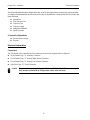
4. For shielded cables with flying leads at one or both ends. It is important to ground the shield at each such
end before the wires exit. Make this ground with absolute minimum length. Refer to Figures 1 and 2.
(A ¼-inch piece of #22 wire may be undesirably long since it has approximately 5 nH of inductance,
equivalent to 31 ohms at 1000 MHz). After picking up the braid ground, keep wires and braid flat against
the case. With very few exceptions, grounded metal covers are not required over terminal strips. If one is
required, it will be stated in the Declaration of Conformity.
5. In selecting the appropriate type and wire size for cables, consider:
A. Voltage ratings.
B. Cumulative I
2
R heating of all the conductors (keep them safely cool).
C. IR drop of the conductors, so that adequate power or signal voltage gets to the controller.
D. Capacitance and inductance of cables that handle fast signals (such as data lines or stepper motor
drive cables).
E. Some cables may need internal shielding from specific wires to others.
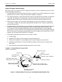
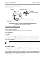
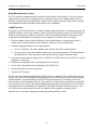
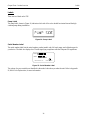
Example 1: Preferred Method to Connect Cable
(shown on a transducer)
Transducer
Overall Insulation
(if present)
Bare Metal Cable Clamp
Making Firm Contact To Braid
Braid Here Is Desirable
(but not usually necessary)
Keep Wires and Braid
Flat Against Case
Metal Cable Clamp
Screw
Split Lock Washer
External Tooth Lock Washer
Transducer Housing
Optional Plastic or Metal Cable
Clamp (For Physical Strain Relief)
Figure 1: Preferred Method To Connect an Overall Metal Braided Shielded Cable
La page est en cours de chargement...
La page est en cours de chargement...
La page est en cours de chargement...
La page est en cours de chargement...
La page est en cours de chargement...
La page est en cours de chargement...
La page est en cours de chargement...
La page est en cours de chargement...
La page est en cours de chargement...
La page est en cours de chargement...
La page est en cours de chargement...
La page est en cours de chargement...
La page est en cours de chargement...
La page est en cours de chargement...
La page est en cours de chargement...
La page est en cours de chargement...
La page est en cours de chargement...
La page est en cours de chargement...
La page est en cours de chargement...
La page est en cours de chargement...
La page est en cours de chargement...
La page est en cours de chargement...
La page est en cours de chargement...
La page est en cours de chargement...
La page est en cours de chargement...
La page est en cours de chargement...
La page est en cours de chargement...
La page est en cours de chargement...
La page est en cours de chargement...
La page est en cours de chargement...
La page est en cours de chargement...
La page est en cours de chargement...
La page est en cours de chargement...
La page est en cours de chargement...
La page est en cours de chargement...
La page est en cours de chargement...
La page est en cours de chargement...
La page est en cours de chargement...
La page est en cours de chargement...
La page est en cours de chargement...
La page est en cours de chargement...
La page est en cours de chargement...
La page est en cours de chargement...
La page est en cours de chargement...
La page est en cours de chargement...
La page est en cours de chargement...
La page est en cours de chargement...
La page est en cours de chargement...
La page est en cours de chargement...
La page est en cours de chargement...
-
 1
1
-
 2
2
-
 3
3
-
 4
4
-
 5
5
-
 6
6
-
 7
7
-
 8
8
-
 9
9
-
 10
10
-
 11
11
-
 12
12
-
 13
13
-
 14
14
-
 15
15
-
 16
16
-
 17
17
-
 18
18
-
 19
19
-
 20
20
-
 21
21
-
 22
22
-
 23
23
-
 24
24
-
 25
25
-
 26
26
-
 27
27
-
 28
28
-
 29
29
-
 30
30
-
 31
31
-
 32
32
-
 33
33
-
 34
34
-
 35
35
-
 36
36
-
 37
37
-
 38
38
-
 39
39
-
 40
40
-
 41
41
-
 42
42
-
 43
43
-
 44
44
-
 45
45
-
 46
46
-
 47
47
-
 48
48
-
 49
49
-
 50
50
-
 51
51
-
 52
52
-
 53
53
-
 54
54
-
 55
55
-
 56
56
-
 57
57
-
 58
58
-
 59
59
-
 60
60
-
 61
61
-
 62
62
-
 63
63
-
 64
64
-
 65
65
-
 66
66
-
 67
67
-
 68
68
-
 69
69
-
 70
70


dans d''autres langues
- English: MKS T3PIA User manual
Autres documents
-
 Hach IO9000 User Instructions
-
 T & S Brass & Bronze Works B-0955 Fiche technique
-
Eurotherm TKS Mode d'emploi
-
Epson ELPIF01 Mode d'emploi
-
-
-
 Lauda Integral XT Mode d'emploi
-
 Cattani MICRO SMART Operator's Handbook Manual
-
Vestfrost MKS 044 SolarChill Instructions For Use Manual
-
Roland MKS-7 Manuel utilisateur


