
EPC-G41
Operating Manual

All product names mentioned in this document are registered trademarks of the respective
owners.
Copyright © Wincor Nixdorf International GmbH, 2010
All rights reserved, particularly (in whole or in part) those of translation, reprint,
reproduction by copying or similar means.
We reserve the right to seek damages for all infringements. All rights, including rights
created by patent grant or registration
of a utility model or design, are reserved. We reserve the right to determine delivery
options or make technical modifications.

EPC-G41
Operating Manual
Edition Nov 2010

Contents
01750196650 B EPC-G41 – Operating Manual
Contents
Manufacturer’s Certification......................................................1
FCC-Class A Declaration.........................................................1
Recycling.....................................................................................2
Safety information......................................................................3
Introduction.................................................................................5
Dimension ................................................................................6
Wiring the EPC-G41.................................................................9
Technical Data..........................................................................10
Motherboard Data ..................................................................10
Block Diagram........................................................................13
Jumper Settings and Connectors Layout...............................14
Climatic requirement ..............................................................15

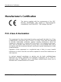
Manufacturer’s Certification
01750196650 B EPC-G41 – Operating Manual 1
Manufacturer’s Certification
The device complies with the requirements of the EEC
directive 2004/108/EC with regard to “Electromagnetic
compatibility” and 2006/95/EC “Low Voltage Directive”.
FCC-Class A Declaration
This equipment has been tested and found to comply with the limits for a Class
A digital device, pursuant to part 15 of the FCC Rules. These limits are designed
to provide reasonable protection against harmful interference when the
equipment is operated in a commercial environment. This equipment generates,
uses, and can radiate radio frequency energy and, if not in-stalled and used in
accordance with the instruction manual, may cause harmful interference to radio
communications.
Operation of this equipment in a residential area is likely to cause harmful
interference in which case the user will be required to correct the interference at
own expense.
Le présent appareil numérique ne génère pas de bruits radioélectriques
dépassant les limites applicable aux appareils numériques de la “Class A”
prescrites dans le Règlement sur le brouillage radioélectrique édicté par le
ministère des Communications du Canada.

Manufacturer’s Certification
01750196650 B EPC-G41– Operating Manual 2
Recycling
The EPC-G41 has been designed according to the Wincor
Nixdorf standard for "Environmentally friendly product
design and development."
The EPC-G41 is manufactured without using CFCs or
CHCs and is made predominantly of recyclable parts and
materials.
For purposes of reuse, it is helpful not to place any additional stickers on the
device.
Wincor Nixdorf disposes of old units in an environmentally friendly manner in
a recycling centre which, like the entire company, is certified according to ISO
9001 and ISO 14001.
Comply with local regulations for removing/disposing of hazardous waste (e.g.
batteries).
Your local representative is available to answer any questions you may have
regarding return, recycling or disposal of our products.

Manufacturer’s Certification
01750196650 B EPC-G41 – Operating Manual 3
Safety information
The EPC-G41 corresponds to the relevant safety regulations for data
processing equipment.
If this system is taken to the installation location from a cold environment,
condensation may appear. As the device must not be started until it is
absolutely dry, allow a temperature adjustment time of at least two hours.
This device is equipped with a safety-tested power cable. It may only be
connected to a safety plug with ground contact that is earthed in compliance
with regulations.
When putting the device into place, make sure that the mounting plug
apparatus and the safety plug with ground contact are readily accessible.
Whenever work of any kind is done on the device, as well as when data
cables are plugged and unplugged, the device must be completely
disconnected from the line voltage. To do so, turn the device off and unplug
the power cord.
Make sure that no foreign objects (such as paper clips) get inside the device,
as electrical shocks or short circuits could result.
Keep the device's ventilation slots clear in order to ensure proper ventilation.
This will avoid excessive temperature increases. Observe the indications
given in the chapter “Setting up the Device”.
During storms, the data cables should not be plugged in or unplugged.
Protect the device from shock, dust, humidity and heat.
In an emergency (for example, damaged housing or damaged power supply
unit, liquid spill or foreign object falling into the unit), turn the device off
immediately and unplug the power cable.
There is a danger of explosion if the device's lithium battery is replaced
incorrectly! The lithium battery may only be replaced with the identical type or
those recommended by the manufacturer.

Manufacturer’s Certification
01750196650 B EPC-G41– Operating Manual 4
You can connect or disconnect USB devices during operation of your EPC-
G41, provided that these devices comply with the specifications according to
usb.org.
Other peripheral devices with higher power requirement (such as Powered
USB printer) should be connected to or disconnected from your EPC-G41
only after the system has been switched off!
You should only connect the EPC-G41, or other information technology
devices, to electrical supplies with a separate earth wire (PE). This type of
electrical supply is called a TN-S power supply system. Do not use PEN
conductors! Also, follow the recommendations of DIN VDE 0100 Part 540,
Addendum C2. By doing so, you avoid possible malfunctions.

Introduction
01750196650 B EPC-G41 – Operating Manual 5
Introduction
The Development of the EPC-G41, for ATM- and Info-Systems takes place
with Standard market components as mini ITX G41, TFX Power supply with
housing and ventilation.
The motherboard will follow the µATX form factor (244mm x 244mm) and the
usage of a TFX - Power Supply. It is also necessary to use “Low Profile” cards
for the extension slots to fulfill the mechanical requirements.
All major parts as hard disk, fan and CPU of the device are easy accessible
(very few screws to access)

Introduction
01750196650 B EPC-G41– Operating Manual 6
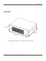
Dimension
Overall dimensions W x H x D: 370mm x 120mm x 310mm
310 mm
370 mm
120 mm

Setting up the device
01750196650 B EPC-G41 – Operating Manual 7
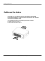
Setting up the device
Set up the EPC-G41 device so that it is not subject to any extreme
environmental conditions. Protect the device from shocks, dust, moisture,
heat and strong magnetic fields.
The ventilation will work in the following described schematic:
air intake at the front of the PC
air exit at the back side of the PC.

Setting up the device
01750196650 B EPC-G41– Operating Manual 8
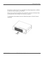
All used fans inside of the PC are regulated according temperature conditions
to keep the noise emission at a low level
Always be sure that all ventilation slots of the EPC-G41 are not blocked, thus
ensuring that the device always has sufficient ventilation.
To guarantee a free intake of the air is 40mm free space in front of chassis
necessary.
40

Setting up the device
01750196650 B EPC-G41 – Operating Manual 9
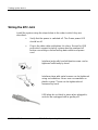
Wiring the EPC-G41
Install the system using the steps below in the order in which they are
described:
Verify that the power is switched off. The Green power LED
should be off.
Plug in the data cable and tighten it in place. Except for USB
ports which support hot-plug, system must be powered off
before connecting or disconnecting data cables and power
cord.
Interface jacks with knurled thumb screws can be
tightened sufficiently by hand.
Interface plugs with metal screws can be tightened
using a screwdriver. Never use a screwdriver on
plastic screws. These can be tightened and
loosened by hand.
USB plugs do not latch in place when plugged in,
and can be unplugged with a gentle pull.

Technical Data
01750196650 B EPC-G41– Operating Manual 10
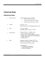
Technical Data
Motherboard Data
Microprocessor
Intel Desktop Processor, LGA775
E7400 Core2Duo 2.8GHz,
E5300 Pentium dual core 2.6GHz,
E1500 Celeron dual core 2.2GHz,
Chipset
Intel G41, ICH7
800/1067/1333 MT/s (200/266/333 MHz) FSB
BIOS
SPI Flash, 16Mbit
Plug-and-Play 1.1, APM, ACPI, DMI
Main Memory
Maximum 4GB on 1x DIMM socket
DDR3 SDRAM, 1066/800MHz
Support 1 GB / 2 GB / 4 GB RAM modules
Support 1Gb, 512Mb DDR3 technologies for
x8 and x16 devices.
Single-channel
Video
Integrated Graphic Controller, 2D & 3D
graphics, video overlay, 3D render engine
Dual independent display support
Analog Display
350MHz, 24-bit RAMDAC
Up to 2048x1536 @ 75 Hz
DDC2B Compliance

Technical Data
01750196650 B EPC-G41 – Operating Manual 11
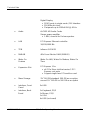
Digital Display
SDVO ports in single mode / DVI Interface
200 MHz dot clock
Flat panels up to 1280x1024 @ 60 Hz
Audio
ALC622 HD Audio Codec
Stereo power amplifier
1.8W / channel for 8 ohms speaker
LAN
PCI Express Ethernet controller
10/100/1000 Mb
TPM
Infineon SLP9635
NVRAM
4Kb Ferro-Electric RAM (SMBUS)
Wake On
Feature
Wake On LAN, Wake On Modem, Wake On
Time
Expansion Slot
PCI Express 1.0a
x4 PCIe Riser slot that carries 3 PCI
Express root ports
Support single-lane PCIe add-on card
Mass Storage
3½” 160 GB standard, 500 GB as an option,
second 3½” 160 GB or 500 GB as an option
Interface, Front
Panel
2x USB
Interface, Back
1x Keyboard, PS/2
Panel 1x Mouse, PS/2
1x VGA
4x USB (on-board)

Technical Data
01750196650 B EPC-G41– Operating Manual 12
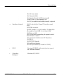
2x USB (via cable)
1x Ethernet (LAN)
1x Standard Serial, COM1 (on-board)
1x MIC/Line In, Line/Speaker Out
1x DVI (via cable+Level-shifter board) - optional
Interface, Internal
1x PCIe x4 slot (for 1-lane PCIe add-on card
only)
2x SATA connector
2x USB header, 2 x 5 pin header, 2.54mm pitch
(1x used for Front USB, 1x for Rear USB)
1x Wake-on-LAN
2x Fan connector supporting fan speed control
thru PWM, 1 x 4 pins
1x Front Panel Interface (incl PC Speaker)
1x SMBUS
1x SDVO/DVI header
1x Parallel port header
3x COM port header (1x used for COM2)
BIOS
Standard PC BIOS with extentions to support
the defined hardware
Operating
Software
Windows XP, LINUX

Technical Data
01750196650 B EPC-G41 – Operating Manual 13
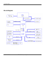
Block Diagram

Technical Data
01750196650 B EPC-G41– Operating Manual 14
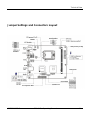
Jumper Settings and Connectors Layout

Technical Data
01750196650 B EPC-G41 – Operating Manual 15
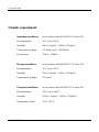
Climatic requirement
Operating conditions in accordance with EN 60721-3-3 class 3K3
Air temperature +5C up to +40C
Humidity 5%r.h. (1g/m3) – 85%r.h. (25g/m3)
Temperature change 0.5 K/min (max. 7.5K/30min)
Air pressure 70kPa – 106kPa
Storage conditions in accordance with EN 60721-3-1 class 1K2
Air temperature +5C up to +40C
Humidity 5%r.h. (1g/m3) – 85%r.h. (25g/m3)
Temperature change 0.5 K/min
Transport conditions in accordance with EN 60721-3-2 class 2K2
Air temperature -25C up to +60C
Humidity 15%r.h. (1g/m3) – 98%r.h. (32g/m3)
Temperature shock -25C / 25C

Published by
Wincor Nixdorf Pte Ltd
2, Kallang Sector
Singapore 349277
Part No.: 01750196650 B
-
 1
1
-
 2
2
-
 3
3
-
 4
4
-
 5
5
-
 6
6
-
 7
7
-
 8
8
-
 9
9
-
 10
10
-
 11
11
-
 12
12
-
 13
13
-
 14
14
-
 15
15
-
 16
16
-
 17
17
-
 18
18
-
 19
19
-
 20
20


dans d''autres langues
Documents connexes
Autres documents
-
MSI MS-7793v3.0 Le manuel du propriétaire
-
Diebold Nixdorf TH210-VI Guide de référence
-
MSI B85-G41 PC Mate Le manuel du propriétaire
-
MSI B75IA-E33 Le manuel du propriétaire
-
-
ASROCK G41MH USB3 Manuel utilisateur
-
-
ASROCK G41MH-LE3 Le manuel du propriétaire
-
ASROCK G41C-GS Le manuel du propriétaire
-
ASROCK G41M-S3 Le manuel du propriétaire