
LP & HIGH ALTITUDE LP GAS CONVERSION KIT
FOR INSTALLATIONS IN CANADA
FOR R8HE / PPG3HE SERIES, CONDENSING STYLE, GAS / ELECTRIC PACKAGE UNITS
BEFORE THE CONVERSION
IMPORTANT: Please read all instructions before
converting the unit. Pay attention to all safety warnings
and any other special notes highlighted in the manual.
Safety markings are used frequently throughout this
manual to designate a degree or level of seriousness and
should not be ignored. WARNING indicates a potentially
hazardous situation that if not avoided, could result in
personal injury or death. CAUTION indicates a potentially
hazardous situation that if not avoided, may result in minor
or moderate injury or property damage
This conversion kit is only to be used to convert natural
gas uits to LP/Propane gas in Canada. This kit may only
be used in furnaces installed in altitudes between zero and
4,500 feet above sea level. For installations in the United
States, the U.S conversion kit must be used.
Table 1. LP Gas Conversion Kit
DESCRIPTION
NORDYNE
P/N
QTY
Honeywell Conversion Kit 50033841
(to convert VR9205Q1127)
624805 1
#55 Drill Size Burner Orifice Kit
(contains (7) 661055)
150602 1
Conversion Warning Label 703935 1
Conversion Information Label 703942 1
Installation Instructions 709636 1
WARNING
FIRE OR EXPLOSION HAZARD
•Failure to follow safety warnings exactly
couldresultinseriousinjuryorproperty
damage.
•Installationandservicemustbeperformed
byaqualiedinstaller,serviceagencyor
thegassupplier.
•Do not store or use gasoline or other
ammablevaporsandliquidsinthevicinity
ofthisoranyotherappliance.
WHAT TO DO IF YOU SMELL GAS
•Donottrytolightanyappliance.
•Donottouchanyelectricalswitch;donot
useanyphoneinyourbuilding.
•Leavethebuildingimmediately.
•Immediatelycallyourgassupplierfroma
neighborsphone.Followthegassuppliers
instructions.
•Ifyoucannotreachyourgassupplier,call
theredepartment.
RISQUE D’INCENDIE OU D’ EXPLOSION
•Lenon-respectdesavertissementsdesécurité
pourraitentraînerdesblessuresgraves,lamort
oudesdommagesmatériels.
•L’installationetl’entretiendoiventêtreeffectués
par un installateur qualié, un organisme de
service ou le fournisseur de gazstaller, service
agencyorthegassupplier.
•Ne pas entreposer ni utiliser de l’essence ni
d’autresvapeursouliquidesinammablesdansle
voisinagedecetappareil,nidetoutautreappareil.
QUE FAIRE S’IL Y A UNE ODEUR DE GAZ
•Nepastenterd’allumeraucunappareil.
•Ne toucher à aucun interrupteur électrique;
n’utiliseraucuntéléphonedanslebâtiment.
•Évacuerl’immeubleimmédiatement.
•Appelerimmédiatementlefournisseurdegazen
employantletéléphoned’unvoisin.Respecterà
la lettre les instructions du fournisseur de gaz.
•Sipersonnenerépond,appelerleservicedes
incendies.
DO NOT DESTROY. PLEASE READ CAREFULLY & KEEP IN A SAFE PLACE FOR FUTURE REFERENCE.
USER'S MANUAL
Table 1 is a detailed listing of the components in the LP
gas conversion kit. Please check the contents of the
conversion kit with that of the parts listing, and familiarize
yourself with each component.

2
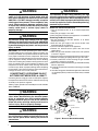
Figure1.Burner&ManifoldAssembly
GAS INLET
ON / OFF
SWITCH
BURNER
ASSEMBLY
SCREWS (X4)
GAS
MANIFOLD
BURNER ORIFICES
3-PIN
CONNECTOR
BURNERS
WARNING:
Allgaspipingmustconformwith local building
codes,orintheabsenceoflocalcodes,withthe
most recent edition of the National Fuel Gas Code
ANSIZ223.1.DONOTattempttomodify,ortapinto
existinggaslinesyourself.Fireorexplosionmay
resultcausingpropertydamage,personalinjury
orlossoflife.Failuretofollowthesafetywarnings
exactly could result in serious injury, death or
propertydamage.
WARNING:
Allelectrical wiring mustcomplywith the latest
edition of the National Electrical Code ANSI/NFPA
70.Failuretofollowtheseinstructionscouldresult
inpossibledamagetoequipment,seriouspersonal
injury,ordeath.
IMPORTANT: The installer performing this work assumes
all responsibility for this conversion. These instructions are
primarily intended to assist qualified individuals experienced
in the proper installation of these components. Some local
codes require licensed installation/service personnel for this
type of equipment. Safety should always be the deciding
factor when installing this product and using common sense
plays an important role as well. Improper installation of the
components or failure to follow safety warnings could result
in serious injury, death, or property damage. After completing
the installation, return these instructions to the Homeowner’s
Package for owner-user’s future reference.
CONVERTING TO LP/PROPANE GAS AT
ALTITUDES BETWEEN ZERO & 4,500 FT.
Converting the two-stage gas valve to LP/Propane requires
the replacement of the burner orifices and/or the stem/spring
assembly in the pressure regulator.
Table 2 (page 4), provides the manifold pressure for altitudes
above 2,000 feet.
WARNING:
Shutoffthegassupplyatthemanualgasshutoff
valve,beforedisconnectingtheelectricalpower.
A re or explosionmayresult causing property
damage,personalinjuryorlossoflife.Failureto
followthesafetywarningsexactlycouldresultin
seriousinjury,deathorpropertydamage.
WARNING:
Toavoidelectricshock,personalinjury,ordeath,
turnofftheelectricpoweratthedisconnectorthe
mainservicepanelbeforemaking anyelectrical
connections.
WARNING:
Thereductionofinputratingnecessaryforhigh
altitudeinstallationmayonlybeaccomplishedwith
factorysuppliedorices.Donotattempttodrillout
oricesintheeld.Improperlydrilledoricesmay
causere,explosion,carbonmonoxidepoisoning,
personalinjuryordeath.
Before You Convert the Gas Valve
1. Turn the thermostat OFF or to its lowest temperature
setting.
2. Verify the gas supply is shut OFF.
3. Verify the electrical power to the appliance is turned OFF.
RemovingTheBurnerOrices
1. Set the thermostat to the OFF position, or its lowest
temperature setting.
2. Shut OFF the gas supply at the manual shutoff valve
located outside of the appliance.
3. Turn off all electrical power to the appliance.
4. Remove the louvered access panel from the burner
compartment.
5. Move the gas valve ON/OFF switch to the OFF position
as shown in Figure 1.
6. Disconnect the 3-wire connector from the gas valve terminal.
7. Remove the supply gas piping from the gas valve inlet.
8. Carefully remove four screws securing the gas manifold
assembly to the burner assembly.
9. Set the screws aside and remove the gas manifold assembly
from the appliance.
10. Carefully remove the burner orifices from the gas manifold
assembly.
11. Read the rating plate affixed to the appliance to determine
its rated input (Btu/hr) and the size of the factory installed
orifices.

3
GAS PRESSURE ADJUSTMENT
MeasuringtheSupplyGasPressure
1. Turn OFF the gas supply at the manual valve located on
the outside of the unit.
2. Using a 3/16” Allen wrench, remove the plug from the inlet
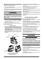
pressure tap (INLET side of gas valve). See Figure 2.
3. Install an 1/8” NPT pipe thread fitting, that is compatible
with a Manometer or similar pressure gauge.
4. Connect the Manometer or pressure gauge to the Inlet
Pressure Tap.
5. Turn ON the main gas supply at the manual valve.
6. Check and adjust the incoming gas line pressure to 11.0-
14.0 inches Water Column for LP/Propane gas.
7. Turn OFF the gas supply at the manual valve.
8. Disconnect the Manometer or pressure gauge.
9. Remove the NPT fitting and reinstall the INLET pressure tap
plug. Hand tighten the plug first to prevent cross-threading.
Tighten with 3/16 Allen wrench.
Lighting&AdjustmentoftheAppliance
WARNING:
FIRE OR EXPLOSION HAZARD
Failuretofollowsafetywarningsexactlycouldresult
inseriousinjuryorpropertydamage.
Nevertestforgasleakswithanopename.Use
a commercially available soap solution made
specicallyforthedetectionofleakstocheckall
connections.Areorexplosionmayresultcausing
propertydamage,personalinjuryorlossoflife.
1. Turn ON the manual gas valve, located on the outside of
the unit to the ON position.
2. Check all gas connections for leaks with a soap and water
solution. If the solution bubbles there is a gas leak which
must be corrected.
3. Turn on the electrical power to the appliance.
4. Place the gas valve ON / OFF switch to the ON position.
See Figure 2.
5. Set the thermostat above room temperature to begin the
heating cycle of the furnace.
IMPORTANTNOTE:Beforeinstallinganorice,check
thesideorfaceoftheoriceforthedrillnumberand
verifythatitistheappropriatesize.
12. Install the appropriate LP/Propane gas burner orifices
into the gas manifold assembly.
NOTE: To prevent cross threading, hand tighten the orifices
into the gas manifold assembly until snug, then tighten
with a wrench 1/2 to 1 full turn.
WARNING:
Do not useTeon tape or pipe joint compound
ontheoricethreads.Theholeintheoricemay
becomeblockedandcausere,explosion,property
damage, carbon monoxide poisoning, personal
injury,ordeath.
13. Reinstall the gas manifold assembly to the burner assembly
with the 4 screws, that were removed earlier. NOTE: It is
important that the center of the orifices are aligned with
the center of the burners.
14. Reconnect the gas piping to the gas valve inlet.
15. Reconnect the 3-wire connector to the gas valve terminal.
Converting the Gas Valve
IMPORTANT NOTES:
• WhenconvertingtoLP/Propanegasfromnaturalgas,
thespringsfromgasvalvemustbereplacedbythe
largerspringsfromthekit.TheLP/Propanesprings
forbothHIGH&LOWrearethesamesize,shape
and color. See Figure 2.
• UseonlyaTorx-25or3/16”atheadscrewdriverwhen
removing adjustment screws or during pressure
adjustment.
Figure2.Two-StageGasValve
(Model VR9205Q1127)
Inlet Pressure Ta p
Manifold
pressure Ta p
ON/OFF
Switch
High Fire
Cap Screw
High Fire
Adjustment Screw
Low Fire
Cap Screw
Low Fire
Adjustment Screw
Spring
Spring
1. Remove the HIGH fire cap screw. See Figure 2.
2. Remove and discard the HIGH fire adjustment screw from
the gas valve.
3. Remove the spring from the gas valve and discard.
4. Install a larger spring from the conversion kit.
5. Install a new adjusting screw from the kit.
6. Repeat steps 1 - 5 for replacement of the LOW fire spring
and adjustment screw.
7. Check and adjust the regulator setting. See Gas Pressure
Adjustment Section.
8. Reinstall the cap screws on the HIGH and LOW regulators.
Plastic replacement cap screws are provided in the
conversion kit.
9. Affix the yellow label from the spring conversion kit to the
gas valve.

6. Check that the furnace ignites and operates properly. Refer
to the installation instructions provided with the unit for the
normal operating sequence.
7. After ignition, visually inspect the burner assembly to
ensure that the flame is drawn directly into the center of
the heat exchanger tube. In a properly adjusted burner
assembly, the flame color should be blue with some light
yellow streaks near the outer portions of the flame.
NOTE: The ignitor may not ignite the gas until all air is bled
from the gas line. If the ignition control locks out, turn the
thermostat to its lowest setting and wait one minute then
turn the thermostat above room temperature and the ignitor
will try again to ignite the main burners. This process may
have to be repeated several times before the burners will
ignite. After the burners are lit, check all gas connections
for leaks again with the soap and water solution.
Measuring the Manifold Pressure
The manifold pressure must be measured by installing a
pressure gauge (Manometer, Magnehelic Meter, etc.) to the
outlet end of the gas valve as follows:
1. Turn off all electrical power to the appliance.
2. Shut OFF the gas supply at the manual shutoff valve
located outside of the appliance.
3. Using a 3/16” Allen wrench, remove the manifold pressure
tap plug located on the outlet side of the gas valve. See
Figure 2.
4. Install an 1/8” NPT pipe thread fitting, that is compatible
with a Manometer or similar pressure gauge.
5. Connect the Manometer or pressure gauge to the manifold
pressure tap.
6. Set the room thermostat above room temperature to start
the furnace.
7. Allow the furnace to operate for 3 minutes and then check
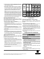
the manifold pressure. Compare the measured value with
the value shown in Table 2. If the manifold pressure is not
set to the appropriate pressure, then it must be adjusted.
Adjusting the Manifold Pressure
NOTE: Adjustments must be made to both LOW & HIGH
fire settings when converting two-stage gas valves. Refer
to Table 2 for manifold pressures.
1. Remove the cap screw (Figure 2, page 3).
2. Using a screwdriver or Allen wrench (where appropriate),
slowly turn the adjustment screw till the appropriate manifold
pressure listed in Table 2 is achieved.
NOTE: Turning the screw clockwise increases the pressure,
turning the screw counter-clockwise decreases the
pressure. To prevent the screw from backing all the way
out from the valve, turn the screw slowly.
3. Replace and tighten the cap screw or the plastic cap over
the adjustment screw.
Removing the Manometer / Pressure Gauge
After the manifold pressure is properly adjusted, the
Manometer or pressure gauge must be removed from the
gas valve.
1. Turn the thermostat to its lowest setting.
2. Turn OFF the main gas supply to the unit at the manual
shut-off valve, which is located outside of the unit.
3. Turn OFF all of the electrical power supplies to the unit.
4. Remove the pressure gauge adapter from the gas valve
and replace it with the 1/8” NPT manifold pressure plug
that had been removed earlier. NOTE: Make sure the plug
is tight and not cross-threaded.
5. Turn ON the electrical power to the unit.
6. Turn ON the main gas supply to the unit at the manual
shut-off valve.
COMPLETING THE CONVERSION
WARNING:
Do not alter or remove the original rating plate
from the furnace.
1. Attach the following labels:
• Theconversionwarninglabel(P/N703935)shouldbe
afxedtotheoutsideoftheunitdoor.
• Theconversioninformationlabel(P/N703942)should
beafxedon the inside of thecontrolarea or the
louveredaccesspanel.
• Verifytheyellowlabelfromthespringconversionkit
isafxedtothegasvalve.
NOTE: Each label should be prominently visible after
installation.
2. Reinstall the appliance door.
3. Run the appliance through 3 complete cycles to assure
proper operation.
7096360(NEW)
Table2.LiquidPropaneConversionChart
(2-StageModels)
MODEL
NUMBER
R8HE
PPG3HE
GAS
VALVE
SETTING
INPUT
ALTITUDE ABOVE SEA LEVEL
0 to
1,999 FT
2,000 to
2,999 FT
3,000 to
4,500 FT
ORIFICE
SIZE
MANIFOLD
PRESSURE
ORIFICE
SIZE
MANIFOLD
PRESSURE
ORIFICE
SIZE
MANIFOLD
PRESSURE
-X24K060X
-X30K060X
High 60,000
55
10.0
55
9.0
55
8.0
Low 39,000 4.2 3.8 3.6
-X36K080X
-X42K080X
High 80,000
55
10.0
55
9.0
55
8.0
Low 52,000 4.2 3.8 3.6
-X48K100X
-X60K100X
High 100,000
55
10.0
55
9.0
55
8.0
Low 65,000 4.2 3.8 3.6
Specifications & illustrations subject to change without notice or incurring obligations (07/15).
O’Fallon, MO, © Nortek Global HVAC LLC 2015. All Rights Reserved.
-
 1
1
-
 2
2
-
 3
3
-
 4
4


Frigidaire R8HE, Three Phase Guide d'installation
- Taper
- Guide d'installation
- Ce manuel convient également à
dans d''autres langues
Documents connexes
-
Kelvinator KG7T(C,L) Guide d'installation
-
GrandAire G7 LP Conversion Kit (Canada) Guide d'installation
-
Kelvinator R6GD Canadian LP Conversion Kit - 904091A Guide d'installation
-
-
Maytag PPG2GF Guide d'installation
-