Yamaha M7CL Manuel utilisateur
- Catégorie
- Mélangeurs audio
- Taper
- Manuel utilisateur
Ce manuel convient également à

M7CL StageMix V5 User Guide
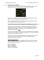
Welcome:
Thank you for downloading the “M7CL StageMix” iPad app for the Yamaha M7CL
digital mixing consoles. This version of StageMix is for use with M7CL firmware V3.5
and higher.
The latest firmware version for M7CL can be downloaded from
www.yamahaproaudio.com
StageMix is an application for the Apple iPad that provides remote control of Yamaha
M7CL digital mixing console functions via a simple, intuitive graphical interface from
anywhere within wireless range. The software has been specifically designed to
allow engineers to adjust monitor mixes from the performers’ positions on stage,
directly controlling mix parameters via the iPad rather than having to rely on verbal
directions to a second engineer. The result is better mixes in less time; a huge
advantage during high-pressure pre-show setup. Although StageMix is focused on
the requirements for adjusting monitor mixes on stage, its range of features is
continually expanding, allowing it to be used for a wider variety of remote control
functions.
Note: iOS applications may not be supported in your area. Please check with your
Yamaha dealer.

Yamaha Professional Audio M7CL StageMix V5 User Guide
Page 2
CONTENTS
Page
1.0 System Requirements ..................................................................................... 5
2.0 Wi-Fi Settings ................................................................................................... 5
3.0 Getting Started ................................................................................................. 6
3.1 M7CL Network Setup ..................................................................................... 6
3.2 iPad Wi-Fi Settings ......................................................................................... 7
3.2.1 Using DHCP............................................................................................. 7
3.2.2 Using a Static IP Address ........................................................................ 8
3.3 StageMix Setup .............................................................................................. 9
3.3.1 OFFLINE DEMO ...................................................................................... 9
3.3.2 Configure StageMix to Work with an M7CL Console ............................. 10
3.3.3 Select a Mixer and Begin Working ......................................................... 11
3.3.4 Edit Mixer Configurations ....................................................................... 11
4.0 Mixer Window ................................................................................................. 12
4.1 Channel Bank Navigation ............................................................................. 12
4.2 Channel Names and Colors ......................................................................... 12
4.3 Faders .......................................................................................................... 13
4.3.1 Long Faders ........................................................................................... 13
4.3.2 Navigation in Long Faders Mode ........................................................... 13
4.4 Channel ON .................................................................................................. 13
4.5 CUE .............................................................................................................. 14
4.6 Master Bank ................................................................................................. 14
4.7 HA GAIN ....................................................................................................... 15
4.7.1 Input Port ............................................................................................... 15
4.7.2 Phantom Power ..................................................................................... 15
4.7.3 Phase ..................................................................................................... 16
4.8 SENDS ON FADERS ................................................................................... 16
4.8.1 Mix Send Levels ..................................................................................... 17
4.8.2 Mix Sends ON ........................................................................................ 17
4.8.3 Mix Send PRE/POST ............................................................................. 17
4.8.4 Global PRE/POST ................................................................................. 18
4.8.5 Stereo Mix Pan ...................................................................................... 18
4.9 DCA FADERS .............................................................................................. 19
5.0 EQ / PAN / DYNAMICS ................................................................................... 20
5.1 EQ ................................................................................................................ 20
5.1.1 EQ Curve in Mixer Window .................................................................... 20
5.1.2 Selecting PEQ or GEQ .......................................................................... 21
5.1.3 Accessing the EQ Editing Screens ........................................................ 21
5.2 PARAMETRIC EQ EDITING ........................................................................ 22
5.2.1 Gain and Frequency Lock ...................................................................... 23
5.2.2 HPF ........................................................................................................ 23
5.2.3 EQ Bands 1 & 4 ..................................................................................... 24
5.2.4 EQ ON ................................................................................................... 24
5.2.5 EQ RESET ............................................................................................. 24
5.2.6 EQ TYPE ............................................................................................... 25
5.2.7 PEQ COPY/PASTE ............................................................................... 25
5.2.8 RTA ON ................................................................................................. 25
5.2.9 RTA HOLD ............................................................................................. 25
5.3 GRAPHIC EQ EDITING ............................................................................... 26

Yamaha Professional Audio M7CL StageMix V5 User Guide
Page 3
5.3.1 Navigation in the GEQ Overview Section .............................................. 26
5.3.2 Rack Position ......................................................................................... 27
5.3.3 GEQ Type .............................................................................................. 27
5.3.4 RTA ON ................................................................................................. 27
5.3.5 RTA HOLD ............................................................................................. 27
5.3.6 GEQ FLAT ............................................................................................. 27
5.3.7 GEQ Copy/Paste ................................................................................... 27
5.3.8 GEQ ON ................................................................................................ 27
5.3.9 Editing GEQ Bands ................................................................................ 28
5.3.10 Navigation in the GEQ Editing Section .................................................. 28
5.4 PAN TO STEREO BUSSES ......................................................................... 28
5.4.1 Balance .................................................................................................. 28
5.5 DYNAMICS PROCESSORS ........................................................................ 29
5.6 DYNAMICS PROCESSOR EDITING ........................................................... 30
5.6.1 Default ................................................................................................... 30
5.6.2 Copy/Paste ............................................................................................ 30
5.6.3 Dynamics On ......................................................................................... 31
5.6.4 Dynamics Type ...................................................................................... 31
5.6.5 Threshold ............................................................................................... 31
5.6.6 Range and Ratio .................................................................................... 31
5.6.7 Other Dynamics Parameters .................................................................. 31
5.6.8 Key In ..................................................................................................... 32
6.0 OUTPORTS ..................................................................................................... 33
6.1 Navigation .................................................................................................... 33
6.2 Output Port Identification .............................................................................. 33
6.3 Delay On ...................................................................................................... 34
6.4 Delay Time Display ....................................................................................... 34
6.5 Output Port Phase ........................................................................................ 34
6.6 Output Port Gain .......................................................................................... 34
6.7 Delay Time Editor ......................................................................................... 34
6.7.1 Delay Scale ............................................................................................ 35
6.7.2 Numeric Keypad .................................................................................... 35
6.7.3 Nudge Delay Time Values ..................................................................... 35
6.7.4 Copy Delay Time Value ......................................................................... 35
6.7.5 Paste Delay Time Value ........................................................................ 36
6.7.6 Close the Delay Time Editor .................................................................. 36
7.0 UTILITY ........................................................................................................... 37
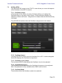
7.1 MUTE GROUP MASTERS ........................................................................... 37
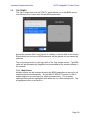
7.2 TAP TEMPO ................................................................................................. 38
7.2.1 Multi-Select ............................................................................................ 38
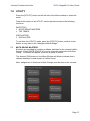
7.3 OSCILLATOR ............................................................................................... 39
7.3.1 Oscillator Assign .................................................................................... 39
7.3.2 Oscillator Output .................................................................................... 39
7.3.3 Oscillator Level Control .......................................................................... 39
7.3.4 Oscillator Frequency .............................................................................. 39
7.3.5 Oscillator Mode ...................................................................................... 39
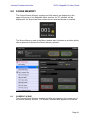
8.0 SCENE MEMORY............................................................................................ 41
8.1 CURRENT SCENE ....................................................................................... 41
8.2 DECREMENT / INCREMENT SCENE ......................................................... 42
8.3 SCENE LIST ................................................................................................ 42

Yamaha Professional Audio M7CL StageMix V5 User Guide
Page 4
8.4 SCENE RANGE ........................................................................................... 42
8.5 SELECTED SCENE ..................................................................................... 43
8.6 STORE SCENE ............................................................................................ 43
8.7 UNDO STORE ............................................................................................. 43
8.8 RECALL SCENE .......................................................................................... 43
8.9 UNDO RECALL ............................................................................................ 44
9.0 SETUP ............................................................................................................. 45
9.1 Fader Delay .................................................................................................. 45
9.2 Cue Mode ..................................................................................................... 45
9.3 Filled EQ Graph ............................................................................................ 45
9.4 Enable Inc/Dec Scene Recall ....................................................................... 45
9.5 Show Send Levels in Meter Bridge ............................................................... 46
9.6 Enable Phantom Power Switching................................................................ 46
9.7 Set EQ band to 0dB with Double-Tap ........................................................... 46
9.8 Show dB Markings on Mixer ......................................................................... 46
9.9 Set DCA to 0dB with Double-Tap ................................................................. 46
9.10 Channel Select – StageMix Follows Console ............................................. 46
9.11 Channel Select – Console Follows StageMix ............................................. 46
9.12 Input Meter Point ........................................................................................ 46
9.13 Output Meter Point ..................................................................................... 46
9.14 Display Key Input for Dynamics Meters ...................................................... 47
9.15 RTA Peak Hold Mode ................................................................................. 47
9.16 RTA Input Gain ........................................................................................... 47
10.0 Troubleshooting ........................................................................................... 48
10.1 No Wi-Fi Available ...................................................................................... 48
10.2 Connection Error ........................................................................................ 48
10.3 Connection Lost ......................................................................................... 49
10.4 DHCP Server Setup on WAP/Router .......................................................... 49
10.5 “Redirect to Internet” Problem with iOS 6 or higher .................................... 49
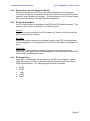
10.6 Graphic EQ Doesn’t Affect the Sound ........................................................ 50
10.7 Problems Moving Multiple Faders .............................................................. 50
10.8 StageMix Facebook Page .......................................................................... 50

Yamaha Professional Audio M7CL StageMix V5 User Guide
Page 5
1.0 System Requirements
• Apple iPad (any model using iOS 6 or higher)
• Yamaha M7CL digital mixing console with V3.5 firmware or higher
• Wi-Fi access point (preferably with 802.11n, 5GHz capability, though 2.4GHz
and 802.11g will also work)
• CAT5 cable (to connect the console to a Wi-Fi access point)
• iOS: iOS 6.0 - 8.x
2.0 Wi-Fi Settings
Configure the Wi-Fi access point, following the manufacturer’s instructions. No
special settings are needed, but using security such as WPA is highly recommended,
to prevent unwanted devices from joining the network. Here are some suggested
settings to assist less experienced Wi-Fi users:
1. Give the wireless network a name (this is the “SSID”).
2. Choose a security mode (such as WPA) and password.
3. Select the wireless mode (802.11g or n).
4. In the case of “n”, select the wireless band (2.4 or 5GHz).
5. If available, enable “Auto Channel Selection” so the wireless channel with the
least interference will be selected.
802.11n networks at 5GHz are preferred because they allow faster communication
between the iPad and the Wi-Fi access point. Practically, this could result in more
accurate level metering with the StageMix app. Using a Wi-Fi access point with 2 or
more external aerials is recommended to increase potential signal range. Booster
aerials could be connected for a further increase in performance.

Yamaha Professional Audio M7CL StageMix V5 User Guide
Page 6
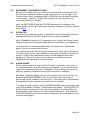
3.0 Getting Started
3.1 M7CL Network Setup
Connect the Wi-Fi access point to the M7CL console’s network port via a
CAT5 cable. Note that a cross-over cable will be needed with older access
points that don’t have the “auto MDIX” function. Most recent devices will
support “auto MDIX”, in which case a straight CAT5 cable can be used.
Make sure your Ethernet cable is connected to a LAN port on your Wi-Fi
device and not the WAN port.
Note the IP address and MAC address of the M7CL console - they will need to
be entered into the iPad later. They can be found in the console as follows:
a. Press the [SETUP] button on the M7CL touchscreen
b. Press [NETWORK] on the M7CL touchscreen

Yamaha Professional Audio M7CL StageMix V5 User Guide
Page 7
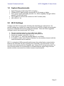
3.2 iPad Wi-Fi Settings
The iPad can be configured using either DHCP or a Static IP address.
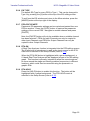
3.2.1 Using DHCP
Dynamic Host Configuration Protocol (DHCP) is a network protocol that
enables a server to automatically assign an IP address to a device.
Use the following steps to configure your iPad using DHCP.
a) Open the iPad “Settings” menu
b) Select “Wi-Fi”, and choose the correct network
c) Press the blue circle with the white arrow to the right of the selected
network to edit the IP address.
d) Select [DHCP] and ensure that your iPad receives data for the IP
Address, Subnet Mask, Router and DNS.
e) Select [Renew Lease] if this data is not applied.
f) If the settings are successfully applied, press the iPad’s Home
button to exit the Settings menu.
Note:
• Make sure that the subnet of the IP address is the same as that of
the M7CL console.
• If DHCP settings are not applied after step (e), please check your
DHCP server settings (refer to 10.4 for further advice). Alternatively,
setup your iPad using a Static IP Address.

Yamaha Professional Audio M7CL StageMix V5 User Guide
Page 8
3.2.2 Using a Static IP Address
a) Open the iPad “Settings” menu
b) Select “Wi-Fi”, and choose the correct network
c) Press the blue circle with the white arrow to the right of the selected
network to edit the IP address.
d) Select [Static]
e) IP Address: enter an IP Address similar to the one for the M7CL
console, but with just the last number different. (For example, if
M7CL is 192.168.0.128, give an address to the iPad such as
192.168.0.127).
f) Subnet Mask: enter “255.255.255.0”.
g) Router: enter the IP Address of your Wi-Fi Access Point (printed on
the bottom of the device or in the user’s manual)
h) DNS: enter the IP Address of your Wi-Fi Access Point (as in step g)
i) Press the iPad’s Home button to exit the Settings menu.

Yamaha Professional Audio M7CL StageMix V5 User Guide
Page 9
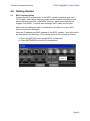
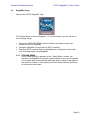
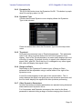
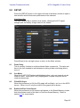
3.3 StageMix Setup
Launch the “M7CL StageMix” App
The “Select Mixer” screen will appear. From this screen, you can do any of
the following things:
• Access the OFFLINE DEMO mode to explore the features and user
interface of M7CL StageMix.
• Configure StageMix to work with an M7CL console.
• Select an M7CL console that has already been configured to work with
your iPad and begin using StageMix.
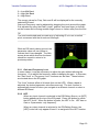
3.3.1 OFFLINE DEMO
If [OFFLINE DEMO] is pressed in the “Select Mixer” screen, the
functions of StageMix will operate independently of any mixing console.
It is a useful way to demonstrate and learn how to use the app without
the need for a mixer. Level meters and most Scene Memory functions
do not work in this mode.

Yamaha Professional Audio M7CL StageMix V5 User Guide
Page 10
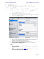
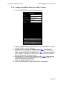
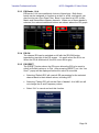
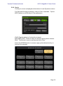
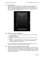
3.3.2 Configure StageMix to Work with an M7CL Console
i. Press [ADD MIXER] to open the following screen:
ii. Tap on the blank Name field and enter a name for your M7CL console
using the iPad’s onscreen keyboard.
iii. Enter the M7CL console’s IP address noted in 3.1. The default IP
Address may not need to be changed but confirm this in the Network
Setup screen of the M7CL console (refer to 3.1). If you need to modify
the IP Address in StageMix, make sure you include the dots between
the sets of numbers (as shown above).
iv. Enter the M7CL console’s MAC address noted in 3.1. When entering
the MAC Address, the colons between sets of characters will be
automatically added by StageMix.
v. Select the Model of M7CL console.
vi. Press the [ADD MIXER] button at the bottom of the screen.

Yamaha Professional Audio M7CL StageMix V5 User Guide
Page 11
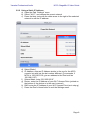
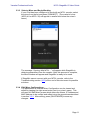
3.3.3 Select a Mixer and Begin Working
If your iPad has been configured to work with an M7CL console, select
the mixer from the list and press [CONNECT]. (The model of mixer
(M7CL-48 or M7CL-32) will appear in smaller text below the mixer’s
name.)
The message “Syncing With M7CL…” will appear while StageMix is
obtaining parameters from the console. After this process is complete,
the Mixer window will appear and StageMix is ready to be used.
If StageMix cannot connect with your M7CL console, refer to the
Troubleshooting section (10.0) at the end of this document for possible
solutions.
3.3.4 Edit Mixer Configurations
The parameters of a saved Mixer Configuration can be viewed and
edited by tapping the right arrow button next to a mixer’s name. This
will open the Edit Mixer screen which allows the Name, IP Address and
MAC Address to be verified and edited using the procedures described
in section 3.3.2. After editing, press [SAVE MIXER] to save any
changes.

Yamaha Professional Audio M7CL StageMix V5 User Guide
Page 12
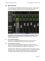
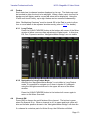
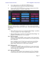
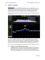
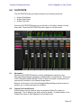
4.0 Mixer Window
The main page of the StageMix is called the “Mixer” window. It shows the EQ
curves, Pan positions, Dynamics status, CUE and ON buttons, faders, level
meters, and channel names and colors for eight adjacent channels.
Across the top of the screen, level meters and faders are displayed in blocks
of channels for mono Input Channels 1-48, Stereo Input Channels 1-4, Mix
and Matrix busses, and the Master Stereo and Mono busses. This is the
“Navigation/Meter Bridge”.
4.1 Channel Bank Navigation
Press any of the “Navigation/Meter Bridge” blocks to select the bank of
channels to be viewed and controlled in the channel strips below.
4.2 Channel Names and Colors
The name of each channel appears in StageMix as it does in the M7CL
console. The names are dimmed if the channel is switched off. A bar above
each channel name displays the color based on the channel type.
Double-tap on the channel name in the Mixer window to edit the name (colors
cannot be edited). Type in a name and press [return]. Alternatively, navigate
to another channel using the left/right cursor buttons above the keyboard.
This allows multiple channels to be named before closing the keyboard.

Yamaha Professional Audio M7CL StageMix V5 User Guide
Page 13
4.3 Faders
Each fader has its channel number displayed on its cap. The fader cap must
be touched to allow the level to be adjusted. When a fader cap is touched, its
background will lighten and its current dB value will be displayed. Using the
iPad’s multi-touch facility, up to eight faders can be moved simultaneously.
Note: “Multitasking Gestures” must be turned Off in the iPad in order to allow
four or more faders to be adjusted simultaneously (refer to 10.7 for details).
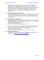
4.3.1 Long Faders
Press the [LONG FADERS] button at the bottom-left corner of the Mixer
window to allow more accurate adjustment of fader levels. In this view,
EQ, Pan, Dynamics and the “Navigation/Meter Bridge” are not visible.
4.3.2 Navigation in Long Faders Mode
Although the “Navigation/Meter Bridge” is not visible in Long Faders
mode, it is possible to navigate up or down in banks of 8 channels
using the left/right arrow buttons in the upper left area of the Mixer
window.
Press the [LONG FADERS] button in the bottom-left corner again to
return to the Mixer Overview.
4.4 Channel ON
Press [ON] to change the on/off status of the channel. The button is green
when the channel is on. When a channel is off, its name and level meter will
dim and its fader position shown in the “Navigation/Meter Bridge” will also dim.
If a channel is muted as part of a Mute Group, the ON button will blink.

Yamaha Professional Audio M7CL StageMix V5 User Guide
Page 14
4.5 CUE
The [CUE] buttons for each channel control the mixer’s Cue functions. Their
operation mode corresponds to the status of the Cue Mode in the Setup
screen (refer to 9.2).
When [LAST CUE] mode is active, only one channel can be cued at a time.
When [MIX CUE] mode is selected, multiple channels can be cued
simultaneously.
The [CUE CLEAR] button will cancel any cues that have been activated. This
is useful when there are multiple cues to cancel, and when some are hidden in
other layers.
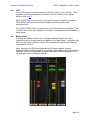
4.6 Master Bank
Pressing the [Master] block in the “Navigation/Meter Bridge” will cause
channels from the master section to appear in the fader strips. Included in this
block are the Stereo Master channel, Mono Master channel and the Monitor
Level and On control.
Note: there are two EQ thumbnails above the Stereo Master channel.
Parametric EQ is always linked for the left and right sides of the Stereo Master
channel. However it is possible to have independent GEQs assigned to the
left and right side of the Stereo Master.

Yamaha Professional Audio M7CL StageMix V5 User Guide
Page 15
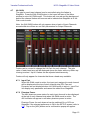
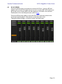
4.7 HA GAIN
The gain for each input channel can be controlled using the faders in
StageMix. Press the [HA GAIN] button in the lower left area of the Mixer
window to enter HA GAIN mode. This button will turn red and the background
behind the channel faders will become red to indicate that StageMix is in HA
Gain control mode.
Note: the [HA GAIN] button will only appear when a bank of Input Channels
are selected since there are no Gain parameters for Output Channels.
Faders can be moved to change the HA Gain for each channel. The gain
value of each head amp will be displayed above the fader while any fader cap
is being touched. Up to 8 faders can be adjusted simultaneously.
Faders will only appear for channels that have a head amp available.
4.7.1 Input Port
When HA GAIN mode is active, the input port assigned to each channel
will be displayed at the top of each channel strip (EQ, Pan and
Dynamics are not displayed when HA GAIN mode is active). Input Port
is a display-only parameter and cannot be edited from StageMix.
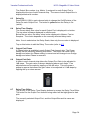
4.7.2 Phantom Power
The 48V phantom power status for each input channel is also displayed
at the top of each channel strip when HA GAIN mode is active. The
48V indicator will appear in red when phantom power is active.
Phantom Power for each channel can be switched On or Off from
StageMix if the relevant preference is ON in the SETUP screen (refer to
9.6). Tap on the [48V] button and a confirmation popup will appear.

Yamaha Professional Audio M7CL StageMix V5 User Guide
Page 16
By default, the 48V phantom power indicators are display-only and
cannot be edited from StageMix.
4.7.3 Phase
The Phase setting for each input channel appears near the top of the
channel strips when HA GAIN mode is active. The Phase setting can
be edited from StageMix by pressing this button. The button will have a
grey background when the Phase setting is normal and will change to
an orange background when Phase is reversed.
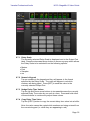
4.8 SENDS ON FADERS
Press the [SENDS ON FADERS] button in the left column of the Mixer screen
to access sends to Mix and Matrix Busses. In “SENDS ON FADERS” mode,
each fader controls the send level from its channel to the currently selected
Mix or Matrix Bus. The fader level indicators in the “Navigation/Meter Bridge”
will show the positions of all the Mix Send Levels if the appropriate Preference
is On in the Setup screen (refer to 9.5).
The large [MIX ON FADERS] button displays the currently selected Mix or
Matrix Bus number and its name. The color of this button matches those used
in the M7CL console.
[CUE] and [ON] buttons appear below the [SENDS ON FADERS] button,
allowing the currently active Mix Bus to be Cued and turned On/Off.
There are two ways to select a target Mix Bus:

Yamaha Professional Audio M7CL StageMix V5 User Guide
Page 17
a) Use a swipe gesture on the [MIX ON FADERS] button to
increment/decrement through the Mix and Matrix Busses.
b) Press the [MIX ON FADERS] button to access a popup screen which
allows direct selection of any Mix or Matrix Bus.
Select the Target from Mix 1-16 and Matrix 1-8. The currently selected Mix
will appear as a white button with a check mark. Stereo pairs appear as single
large buttons.
Notes:
• When a Mix block is active in the “Navigation/Meter Bridge”, only Matrix
1-8 will be available in the “Select Target” popup.
• When the Matrix block is selected in the “Navigation/Meter Bridge”, the
[SENDS ON FADERS] button is not available.
4.8.1 Mix Send Levels
When in “SENDS ON FADERS” mode, the fader in each channel strip
controls the level being sent from that channel to the currently selected
Mix or Matrix Bus.
Note: if a Mix Bus is set to “Fixed” mode, send levels to that Mix Bus
are fixed at 0dB and cannot be adjusted. Mix Send faders will not
appear when a Mix Bus set to “Fixed” mode is selected.
4.8.2 Mix Sends ON
In “SENDS ON FADERS” mode, the [ON] button in each channel strip
is used to turn On/Off the Mix Send from each channel to the currently
selected target Mix or Matrix Bus.
4.8.3 Mix Send PRE/POST
The send from each channel can be assigned to be Pre or Post fader.
A button above the meter in each channel strip displays the Pre/Post

Yamaha Professional Audio M7CL StageMix V5 User Guide
Page 18
state and can be pressed to change the state. The [PRE] button
appears yellow when On and grey when Off.
4.8.4 Global PRE/POST
Press and hold a [PRE] button to make global Pre or Post fader
assignments. A popup will appear providing the following options:
• ALL MIX/MATRIX BUSSES PRE FOR THIS CHANNEL
• ALL MIX/MATRIX BUSSES POST FOR THIS CHANNEL
• CURRENT MIX/MATRIX BUS PRE FOR ALL CHANNELS
• CURRENT MIX/MATRIX BUS POST FOR ALL CHANNELS
4.8.5 Stereo Mix Pan
When a Stereo Mix Bus is active as the “Target Mix Bus”, a Pan slider
will be available at the top of each channel strip in “SENDS ON
FADERS” mode. Adjusting this slider will change the Pan position for
that channel’s send to the currently active Stereo Mix Bus. The Pan
position’s numerical value appears above the slider.
If the Pan Link function is active for the currently active Stereo Mix Bus,
a link icon will appear below the Pan slider. When Pan Link is active,
adjusting a channel’s Pan slider will affect the Pan parameter for that
channel to the Master Stereo Bus and all other linked Stereo Mix
Busses.
Note: Pan Link mode for each Stereo Mix Bus can only be activated in
the console, not from StageMix.
To exit “SENDS ON FADERS” mode, press the [SENDS ON FADERS] button
in the left column.

Yamaha Professional Audio M7CL StageMix V5 User Guide
Page 19
4.9 DCA FADERS
Press the [DCA] button to access the console’s 8 DCAs. A green LED will
appear next to each DCA fader when it is set to exactly 0dB. DCA faders can
be quickly set to exactly 0dB by double-tapping on the fader if the relevant
Preference is On in the Setup screen (refer to 9.9).
Press the [DCA] button again to exit the DCA fader bank and return to the
previously selected bank. Alternatively, press any bank in the
“Navigation/Meter Bridge” to directly access that fader bank.

Yamaha Professional Audio M7CL StageMix V5 User Guide
Page 20
5.0 EQ / PAN / DYNAMICS
The thumbnail area at the top of each channel strip displays an EQ curve, the
Pan position, or Dynamics status for that channel.
The buttons to the left of the thumbnails are used to select between EQ, PAN
and Dynamics mode by tapping on the left or right cursor button.
5.1 EQ
Every channel in the M7CL console has a dedicated Parametric EQ (PEQ).
M7CL consoles also have Graphic EQs (GEQs) that can be assigned
(inserted) on input or output channels.
Note: assignment of GEQs to channels must be done on the console and
cannot be done in StageMix.
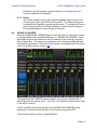
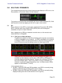
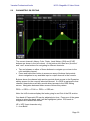
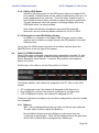
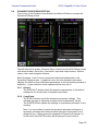
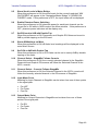
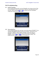
5.1.1 EQ Curve in Mixer Window
The EQ curve section on the Mixer Window will show the user whether
a GEQ is available on any channel. If a GEQ is available on a channel
in addition to PEQ, the user will be able to view the curve for either of
these EQs and access the editing screen for either type of EQ.
Green and blue dots below each EQ curve indicate the types of EQ
available on that channel, and the type of EQ (PEQ or GEQ) that is
currently displayed for that channel. A green dot indicates PEQ and a
blue dot indicates GEQ. When only PEQ is currently available on a
channel, no dots will appear below the curve. (In Demo mode, GEQs
appear on Mix busses1, 7 and 8).
In the example above:
• Mix Bus 1 has both PEQ and GEQ available, and GEQ is currently being
displayed (the blue dot is solid and the curve is blue).
• Mix Bus 2 has both PEQ and GEQ available, and PEQ is currently being
displayed (the green dot is solid and the curve is green).
La page charge ...
La page charge ...
La page charge ...
La page charge ...
La page charge ...
La page charge ...
La page charge ...
La page charge ...
La page charge ...
La page charge ...
La page charge ...
La page charge ...
La page charge ...
La page charge ...
La page charge ...
La page charge ...
La page charge ...
La page charge ...
La page charge ...
La page charge ...
La page charge ...
La page charge ...
La page charge ...
La page charge ...
La page charge ...
La page charge ...
La page charge ...
La page charge ...
La page charge ...
La page charge ...
La page charge ...
-
 1
1
-
 2
2
-
 3
3
-
 4
4
-
 5
5
-
 6
6
-
 7
7
-
 8
8
-
 9
9
-
 10
10
-
 11
11
-
 12
12
-
 13
13
-
 14
14
-
 15
15
-
 16
16
-
 17
17
-
 18
18
-
 19
19
-
 20
20
-
 21
21
-
 22
22
-
 23
23
-
 24
24
-
 25
25
-
 26
26
-
 27
27
-
 28
28
-
 29
29
-
 30
30
-
 31
31
-
 32
32
-
 33
33
-
 34
34
-
 35
35
-
 36
36
-
 37
37
-
 38
38
-
 39
39
-
 40
40
-
 41
41
-
 42
42
-
 43
43
-
 44
44
-
 45
45
-
 46
46
-
 47
47
-
 48
48
-
 49
49
-
 50
50
-
 51
51


Yamaha M7CL Manuel utilisateur
- Catégorie
- Mélangeurs audio
- Taper
- Manuel utilisateur
- Ce manuel convient également à
dans d''autres langues
- italiano: Yamaha M7CL Manuale utente
- English: Yamaha M7CL User manual
- español: Yamaha M7CL Manual de usuario
- Deutsch: Yamaha M7CL Benutzerhandbuch
- русский: Yamaha M7CL Руководство пользователя
- Nederlands: Yamaha M7CL Handleiding
- português: Yamaha M7CL Manual do usuário
- dansk: Yamaha M7CL Brugermanual
- polski: Yamaha M7CL Instrukcja obsługi
- čeština: Yamaha M7CL Uživatelský manuál
- svenska: Yamaha M7CL Användarmanual
- Türkçe: Yamaha M7CL Kullanım kılavuzu
- suomi: Yamaha M7CL Ohjekirja
- română: Yamaha M7CL Manual de utilizare