Fisher Paykel CG365DLPRX2N Guide d'installation
- Taper
- Guide d'installation

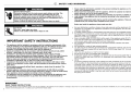
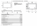
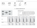
GAS COOKTOP
CG365DW models
INSTALLATION GUIDE
US CA
590686 D 08.17


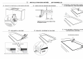
8
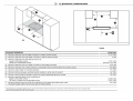
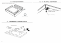
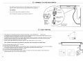
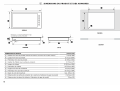
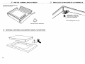
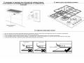
9 SECURE TO COUNTERTOP WITH BRACKETS BASED ON THE COUNTERTOP THICKNESS
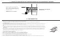
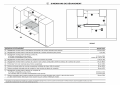
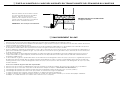
!0 GAS CONNECTION
Place the cooktop into the cutout and
tighten it with the supplied clamps. These
will cope with the countertop thicknesses
3/4”- 2” (19 - 50 mm)when used in the two
orientations shown.
IMPORTANT! - Do not over tighten.
REPEAT ON ALL THE OTHER SIDES
(Total 6 brackets)
3/4” - 2”
(19 mm - 50 mm)
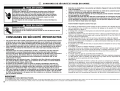
● Make sure the connection point will be accessible with the cooktop installed.
● To enable the gas supply to be readily shut off by the customer, make sure the connection is fitted with an isolating valve
close to the cooktop.
● The appliance must be isolated from the gas supply piping system by closing its individual shut-off valve during any pressure testing of the
gas supply piping system at test pressures at or less than 1/2 p.s.i. (3.5 kPa).
● Maximum inlet gas supply pressure 20” W.C. (5 kPa). Minimum gas supply pressure for regulator testing 5” W.C. Natural Gas / 12” W.C LP
gas.
● A manual shut-off valve must be installed in an accessible location in the gas line external to the appliance for the purpose of turning on or
shutting off gas to the appliance. (In Massachusetts, such shut-off devices should be approved by the Board of State Examiners of Plumbers
& Gas Fitters).
● Gas connection to the product must use the nipple supplied with a 1/2” NPT external thread. The supplied gas pressure regulator must be
installed where it will be accessible for adjustment. The metal flexible hose used must be new, CSA or UL-approved, and must have a 1/2”
NPT external thread on one end and a 1/2” NPT one on the other
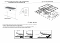
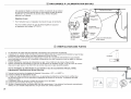
If connecting the gas with a flexible hose
● Ensure the hose is long enough to allow for removal of cooktop for servicing.
● Make sure the connector is located as shown in step 5 CLEARANCE DIMENSIONS.
● The hose assembly must be with an Rp 1/2” (ISO 7-1) female thread connection.
● The hose assembly must be as short as practicable and comply with the relevant requirements.
● The hose must not be kinked, subjected to abrasion or permanently deformed.
● The hose must not be near or in contact with any hot surfaces (e.g. base of metal hotlplate, flue, or chassis of undercounter oven etc.)


11
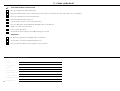
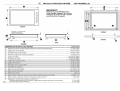
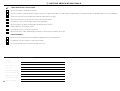
!6 FINAL CHECKLIST
TO BE COMPLETED BY THE INSTALLER
Have you installed the clamping brackets?
Have you verified that the type of model (factory-set for NG or LP) matches the type of gas at the site of installation?
Have you sealed all connections with gas tape?
Have you leak-tested all connections?
Is the cooktop set to the correct working pressure?
Have you affixed the supplied duplicate data plate label on an adjacent
surface accessible to the customer?
Is the cooktop grounded?
Check that the power supply cord is NOT touching the cooktop.
OPERATION:
Do all burners ignite both individually and in combination?
Are the flames consistent and appropriately sized?
Have you demonstrated the basic operation to the customer?
Complete and keep for safe reference:
Model
Serial No.
Purchase Date
Purchaser
Dealer Address
Installer’s Name
Installer’s Signature
Installation Company
Installation Date

12


SURFACE DE CUISSON AU GAZ
Modèles CG365DW
INSTRUCTIONS D’INSTALLATION
CA
590686D 08.17


La page est en cours de chargement...
La page est en cours de chargement...
La page est en cours de chargement...
La page est en cours de chargement...
La page est en cours de chargement...
La page est en cours de chargement...
La page est en cours de chargement...
La page est en cours de chargement...
-
 1
1
-
 2
2
-
 3
3
-
 4
4
-
 5
5
-
 6
6
-
 7
7
-
 8
8
-
 9
9
-
 10
10
-
 11
11
-
 12
12
-
 13
13
-
 14
14
-
 15
15
-
 16
16
-
 17
17
-
 18
18
-
 19
19
-
 20
20
-
 21
21
-
 22
22
-
 23
23
-
 24
24
-
 25
25
-
 26
26
-
 27
27
-
 28
28


