
Installation Guide
1
MRI Compatible
Important Safety Instructions
When using electrical equipment, basic safety precautions should always
be followed including the following:
Read And Follow All Safety Instructions
RF Facility Filter
1. Warning: This product must be installed in accordance with the NEC or your
local electrical code. If you are not familiar with these codes and require-
ments, consult a qualied electrician. Aenon: Ce produit doit être installé
conformément au NEC ou à votre code électrique local. Si vous n’êtes pas fami-
lier avec ces codes et exigences, consultez un électricien qualié.
2. Warning: This equipment is not for use in hazardous combusble atmo-
spheres as dened by the Naonal Electrical Code. Averssement: Cet équi-
pement ne doit pas être ulisé dans des atmosphères combusbles dangere-
uses telles que dénies par le Naonal Electrical Code.
3. Danger: Risk of shock - Disconnect power before installaon. Danger: Risque
de choc – Couper l’alimentaon avant l’installaon.
4. Cauon: Do not over torque. Refer to labeling specicaons for torque
(Nm) specicaons. Aenon: ne pas trop serrer. Se référer aux spécicaons
d’équetage pour les spécicaons de couple (Nm).
Save These Instructions For Future Reference
Installation:
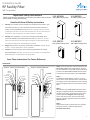
Diagram 1 - Shielding in Equipment Room NOTE: The RF Facility Filter must be installed in the
EQUIPMENT ROOM. Two people will be required
for the installation, one to hold the RF Facility Filter
in place in the EQUIPMENT ROOM and one person
to secure the RF Facility Filter in the SCAN ROOM.
Step 1:
The Male Threaded Adapter measures 1 inch x 2
inches. Drill a 1 inch diameter hole in the intended
mounting surface of the equipment room ensuring
there is enough clearance to mount the RF Facility
Filter.
Step 2:
Note whether the Shielding Material of the wall is
facing the Equipment Room or the MRI Room, this
will determine how to secure the RF Facility Filter
in place. Reference Diagram 1 or 2 depending
on the wall construction. Secure the RF Facility
Filter by using the supplied hardware as shown in
Diagram 1 or 2.
Step 5:
Reference the project specific plans for complete
wiring instruction to make the appropriate
Electrical Connections.
3-01-000008
30A 2-Wire Facility Filter
3-01-000007
15A 4-Wire Facility Filter
3-01-000010
1A 2-Wire Facility Filter
3-01-000011
0.5A 2-Wire Facility Filter
FACILITIES
FILTER
SMALL NUT
MESH WASHER
PLYWOOD
SHIELDING
MATERIAL
RFGASKET
WASHER
JUNCTION
BOX
LARGE NUT
SMALL NUT
FACILITIES
FILTER
SMALL NUT
WASHER
PLYWOOD
SHIELDING
MATERIAL
RFGASKET
MESH WASHER
JUNCTION
BOX
LARGE NUT
SMALL NUT
Diagram 2 - Shielding in MRI Room

2
Directive 2012/19/EU (WEEE - Waste Electrical and Electronic Equipment): Information for Users
This product complies with EU Directive 2012/19/EU. The crossed out wheeled bin symbol on the article means that at the end of its useful lifespan, this product must not be disposed
of with your other household or municipal waste. This product has required the extraction and use of natural resources for its production. It may contain hazardous substances that
could impact health and the environment if not properly disposed. In order to avoid dissemination of those substances in our environment and to diminish the pressure on the natural
resources, the user is responsible for delivering the appliance to an appropriate collection facility at the end of its useful lifespan. The separate collection and recycling of your waste
equipment at the time of disposal will help conserve natural resources and ensure that it is recycled in a manner that protects human health and the environment. For more information
on available collection facilities contact your local waste collection service or the place of purchase.
Amico Lights Corporation | 122-B East Beaver Creek Road, Richmond Hill, ON L4B 1G6, Canada | www.amico.com
Toll Free Tel: 1.877.462.6426 | Toll Free Fax:1.866.440.4986 | Tel: 905.764.0800 | Fax: 905.764.0862
For informational purposes only. Content is subject to change.
ALT-INSTALL-MRI-FACILITY-FILTER-RF 01.18.2021
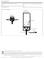
Note:
Ground MUST be connected before power is turned on.
Step 1:
Connect ground (PE) in filter junction box to MRI ground lug located
on the penetration panel.
Step 2:
Connect wires line (L) wire and neutral (N) wire on Equipment room
side.
Step 3:
Connect wires line (L) wire and neutral (N) wire on Scan room side.
Electrical Connections:
Diagram 3 - Electrical Connections
WIRE 2
N
WIRE 1
L
Facility Filters
Scan Room Side
L
PE
N
WIRE 2
WIRE 1
Ground lug on pen panel
WIRE NUMBER
Facility Filters
Equipment Room Side
-
 1
1
-
 2
2


dans d''autres langues
Documents connexes
Autres documents
-
Lincoln Electric LN-25 Pro Mode d'emploi
-
Miller ARCREACH 16 WIRE FEEDER Manuel utilisateur
-
-
-
Lincoln Electric LN-7 Mode d'emploi
-
-
-
-