
Instructions d’installation - Garantie
Installation Instructions - Warranty
www.KaliaStyle.com
Conserver ce guide après l’installation car il contient des informations utiles pour le service et la garantie.
Keep these instructions after you have nished the installation, it contains useful information regarding service and warranty.
Numéro de série/Serial number
102657_RevI 02/20
KONCEPTMC/TM
Base de douche rectangulaire
en acrylique
Acrylic rectangular shower base

2
102657_RevI
Merci d’avoir choisi un produit Kalia et de faire conance à
notre entreprise.
Kalia a une philosophie d’affaires basée sur des valeurs
fondamentales dont l’innovation et l’excellence ainsi qu’un
service personnalisé adapté aux exigences d’aujourd’hui et de
demain. Nous sommes convaincus que ce produit saura vous
plaire et surpassera vos exigences en termes de abilité et
durabilité. Nous sommes là pour vous!
Dans ce guide vous trouverez toute l’information nécessaire à
l’installation et au bon fonctionnement de votre produit Kalia.
Dans le but d’assurer une installation et une utilisation
optimales veuillez prendre quelques minutes pour étudier ce
guide.
En cas de problème d’installation ou de performance, veuillez
communiquer avec nous au numéro sans frais 1 877 GO KALIA
(1-877-465-2542) ou par courriel au [email protected].
Nous vous remercions encore une fois d’avoir choisi un
produit Kalia.
Merci d’avoir choisi Kalia !
Thank you for choosing a Kalia product and for placing your
trust in our company.
Kalia has a business philosophy based on solid core values
that are focused on providing innovation and excellence as
well as a personalized service designed to meet the changing
needs of today and tomorrow.
We are convinced that you will be fully satised with your
new Kalia product and that it will exceed your expectations
in terms of reliability and durability. At Kalia, we put our
expertise to work for you!
This guide contains all the information necessary for the
installation and proper use of your Kalia product. To ensure
the smooth installation and optimal use of your product, we
recommend to take a few moments to study the information
provided in this guide.
In the event that you should encounter a problem related to the
installation or the performance of this product, please contact
us at our toll-free line 1 877 GO KALIA (1-877-465-2542)
or by email at: [email protected].
Thank you once again for choosing Kalia.
Thank you for choosing Kalia!

3
102657_RevI
Renseignements importants
IMPORTANT
- Lire attentivement le présent guide avant l’installation.
- Respecter tous les codes de plomberie et de bâtiment locaux.
- Assurez-vous d’avoir tous les outils et matériaux nécessaires
à l’installation.
- Il est recommandé de porter des lunettes de sécurité en tout
temps lors de l’installation.
- La base de douche doit être installée de niveau sur un
plancher et des murs également de niveau.
- La structure du plancher doit pouvoir supporter un poids de
50 lbs par pied carré (244 kg/m²).
- Les brides de carrelage doivent être installées conformément
aux instructions d’installation an que la base de douche
respecte les normes de certication.
- Le poids de la base doit reposer sur le plancher. En aucun
cas ce poids ne doit être supporté par la bride de carrelage
ou le tablier de la base.
REMARQUE:
- Utiliser le modèle imprimé sur la boîte d’emballage an de
protéger le fond de la base lors de l’installation.
-
Couvrir le drain de la douche an d’éviter de perdre des pièces.
- Avant l’installation, déballer la base de douche et vérier
qu’elle est en bon état. Si un problème survient, le signaler
immédiatement au vendeur.
- Avant d’installer la base de douche, toute l’ossature
(charpente) et la plomberie doivent être complétées
conformément aux instructions et aux normes locales.
- S’il s’agit de travaux de rénovation, les surfaces murales
existantes doivent être enlevées pour installer l’ossature
appropriée.
- Pour faciliter la mise de niveau, il est recommandé d’étendre
du mortier sur la surface du plancher où sera installée la
base. Utiliser le mortier vendu en quincallerie.
- Avant d’appliquer du calfeutrant, de la colle ou mortier,
nettoyer les surfaces à l’aide d’un linge doux et humide.
- Les trous percés dans la bride de carrelage doivent être
percés de l’intérieur (surface nie) vers l’extérieur et
doivent être calfeutrés pour former une barrière étanche à
l’eau.
Kalia se réserve le droit d’apporter toute modication au
design du produit et ceci sans préavis. Utiliser le manuel
d’installation fourni dans l’emballage.
Kalia n’est pas responsable des problèmes causés par une
installation non conforme aux directives énoncées dans le
présent guide.
Bonne installation !
Important Information
IMPORTANT
- Read this guide before proceeding with the installation.
- Respect all local plumbing and building codes.
- Make sure you have all the tools and materials needed for
installation.
- It is recommended to wear safety glasses at all times during
the installation.
- The shower base must be installed perfectly levelled on a
oor and walls that are also perfectly levelled.
- The oor structure must be strong enough to support 50
pounds per square foot (244 kg/m²).
- The tiling ange kit must be installed in accordance with the
installation instructions so that the shower base meets the
certication standards.
- The weight of the shower base must rest on the oor. No weight
should be supported by the tiling ange or the base skirt.
COMMENT:
- Use the protector printed on the packaging box to protect
the bottom of the base during installation; .
- Cover the drain of the shower so no parts are lost.
- Before installing, take the shower base out of the packaging
and make sure the base is in good shape. If there is a
problem, report it immediately to the seller.
- Prior to install the shower base, all framing and plumbing
work must be completed in accordance with instructions
and local codes.
- For renovation work, existing shower surfaces must be
removed to accomodate framing requirements.
- To facilitate leveling, it is recommended to apply mortar on
the oor surface where the shower base will be installed.
Use mortar sold in hardware store.
- Clean surfaces with a soft wet cloth before applying any
caulking, glue or mortar.
- All the holes drilled in the tiling ange must be done from
the inside (nished surface) towards the outside and caulked
to form a water-tight barrier.
Kalia reserves the right to make any changes to the design of
the product, without notice. Use the installation instruction
supplied with the product.
Kalia is not responsible for problems caused by an installation
not executed in accordance with the directions given in this guide.
Good installation!

4
102657_RevI
F*
E*
C
D
AB
C
D
Installation avec drain à gauche illustrée.
Left-hand drain installation shown.
Instruction Part list_Bases RevH.xlsx
* KONCEPT RevH *
[ /Volumes/public/1.KALIA/1._R&D/5.Guides_d'installation/6. Bases de douche/Instruction Part list_Bases RevH.xlsx ]
Longueur Profondeur
Drain profondeur
Drain largeur
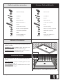
Description Co de/Model A B C D E* F*
Rectangulaire avec brides de carrelage intégrées sur 3 murs/Rectangular with integrated tiling flanges on 3 walls
36'' x 36'' BW1755
Drain central/Central drain — — 457 mm (18'') 457 mm (18'') 914 mm (36'') 914 mm (36'')
48'' x 36'' BW1279
Drain central/Central drain
— — 457 mm (18'') 609,6 mm (24'') 1219 mm (48'') 914 mm (36'')
BW1457
Drain à gauche/Left drain — — 381 mm (15") 232 mm (9 1/8") 1518 mm (59 3/4") 762 mm (30")
BW1458
Drain à droite/Right drain — — 381 mm (15") 232 mm (9 1/8") 1518 mm (59 3/4") 762 mm (30")
BW1414
Drain à droite/Right drain — — 406 mm (16'') 222 mm (8 3/4") 1518 mm (59 3/4") 813 mm (32'')
BW1415
Drain à gauche/Left drain — — 406 mm (16'') 222 mm (8 3/4") 1518 mm (59 3/4") 813 mm (32'')
60'' x 36'' BW1282
Drain central/Central drain — — 457 mm (18'') 762 mm (30'') 1524 mm (60'') 914 mm (36'')
Rectangulaire avec brides de carrelage intégrées sur 2 murs/Rectangular with integrated tiling flanges on 2 walls
36'' x 36'' BW1453
Drain en coin/Corner drain 914 mm (36'') 914 mm (36'') 305 mm (12'') 305 mm (12'') — —
BW1280
Drain central et brides à droite/
Central drain and right flanges
1219 mm (48'') 914 mm (36'') 457 mm (18'') 609,6 mm (24'') — —
BW1281
Drain central & brides à gauche/
Central drain & left flanges
1219 mm (48'') 914 mm (36'') 457 mm (18'') 609,6 mm (24'') — —
BW1809
Drain central et brides à droite/
Central drain and right flanges
1524 mm (60'') 813 mm (32'') 406 mm (16'') 762 mm (30'') — —
BW1808
Drain central et brides à gauche/
Central drain and left flanges
1524 mm (60'') 813 mm (32'') 406 mm (16'') 762 mm (30'') — —
BW1283
Drain central et brides à droite/
Central drain and right flanges
1524 mm (60'') 914 mm (36'') 457 mm (18'') 762 mm (30'') — —
BW1284
Drain central et brides à gauche/
Central drain and left flanges
1524 mm (60'') 914 mm (36'') 457 mm (18'') 762 mm (30'') — —
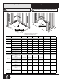
* Ces dimensions sont celle de l'unité. Pour faciliter l'installation, ajo uter 6 mm (1/4'')/Those measurements are those of the unit. For easier installation add 6 mm (1/4'')
Base de douche rectangle Koncept
60'' x 32''
48'' x 36''
60'' x 36''
60'' x 30''
60'' x 32''
Dimensions Measurements
Les dimensions de la structure doivent être vériées
à partir des dimensions de l’unité. Structure measurements must be veried against the unit.
Installation en alcôve/Alcove installationInstallation en coin/Corner installation

5
102657_RevI
Perceuse électrique
Tournevis
Crayon
Ruban à mesurer
Mèche 5 mm (3/16”)
Niveau
Calfeutrant au silicone
Mortier ou ciment égalisateur
Cales de bois (facultatif)
Drain
Vis #8 x 32 mm (1¼”)
(Acier inoxydable)
Electric drill
Screwdriver
Pencil
Measuring tape
5 mm (3/16”) drill bit
Level
Silicone caulking
Mortar or leveling compound
Wood shims (optional)
Drain
Screws #8 x 32 mm (1¼”)
(stainless steel)
Outils et matériaux nécessaires Necessary Tools and Materials
Installation Methods
The acrylic shower base can be installed following three
methods;
Corner Installation: the base is installed against two walls
(refer to pages 6 to 8) (g. A).
Alcove Installation: the base is installed between three walls
(refer to pages 9 to 11) (g. B).
Méthodes d’installation
La base de douche en acrylique peut être installée selon les
méthodes suivantes ;
Installation en coin : Installation contre deux murs (voir
pages 6 à 8 du présent manuel d’installation) (g. A).
Installation en alcôve : Installation entre 3 murs (voir pages 9
à 11 du présent manuel d’installation) (g. B).
INSTALLATION EN COIN/CORNER INSTALLATION
INSTALLATION EN ALCÔVE/ALCOVE INSTALLATION
Fig. A
Fig. B

6
102657_RevI
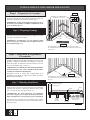
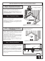
Step 1 - Preparing Framing
The shower base must be installed directly against the studs,
not against the nished wall (g. 1).
IMPORTANT: An additional 2”x4” stud should be added
to the wall structure to facilitate and strengthen the shower
door installation (g. 1.1).
La base de douche doit être installée directement contre les
montants d’ossature et non contre le mur ni (g. 1).
IMPORTANT : Ajouter un montant d’ossature de 2”x4” à
la structure pour faciliter et solidier l’installation d’une
porte de douche (g. 1.1).
Fig. 1
Fig. 1.1
Montant 2”x4” supplémentaire
Additional 2”x4” stud
B - 35 mm
(1 3/8’’) A - 35 mm
(1 3/8’’)
Voir dimensions A et B selon le modèle de la base à la page 4.
See A and B dimensions according to the model of the shower base
on page 4W.
Step 2 - Plumbing Installation
Mark the drain location. Cut or drill the oor to accommodate
plumbing. The 50 mm (2”) drain pipe should be about 19 mm
(3/4”)* below the oor line (g. 2 and g. 2.1).
*IMPORTANT: The drain dimensions and installation
instructions might vary according to the model of drain used.
Refer to manufacturer’s instructions for proper installation.
Position the base and make sure the draining pipe location
matches the actual location of the shower base drain. Remove
the shower base.
Étape 2 - Installation de la plomberie
d’évacuation
Marquer l’emplacement du drain. Découper ou percer le trou
du drain et installer la plomberie d’évacuation. Le tuyau de
renvoi de 50 mm (2”) doit être à environ 19 mm (3/4”)* sous
le niveau du plancher (g. 2 et g. 2.1).
*IMPORTANT : Les dimensions et instructions d’installation
du drain peuvent varier selon le modèle de drain utilisé.
Consulter les instructions du fabriquant.
Positionner la base et vérier que l’emplacement de la
plomberie d’évacuation est aligné avec le drain de la base.
Retirer la base de douche.
Fig. 2
C
Voir dimensions C et D selon le modèle de la base à la page 4.
See C and D dimensions according to the model of the shower base
on page 4.
127 mm
(5”) min.
Plancher de béton
Concrete floor
Base
Plancher
de bois
Wood floor
Montants d’ossature
Framing studs
Drain
38 mm (1 1/2”) min.
Fig. 2.1
D
Étape 1 - Préparation de l’ossature
INSTALLATION EN COIN/CORNER INSTALLATION

7
102657_RevI
Base de douche
Shower base
Calfeutrant
Caulking
Pomelle*
Cover*
Corps du renvoi*
Drain body*
Joints d’étanchéité*
Gaskets*
Écrou du drain*
Drain nut*
Rondelle*
Washer*
Drain non inclus
Drain not included
Fig. 3
Mortier
Mortar
Fig. 4.1
Fig. 4.3
heures
hours
24
Fig. 4.2
Dessous de la base
Bottom of the base
Adhésif de type polyuréthane
Polyurethane-type adhesive
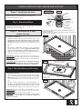
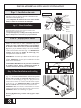
Step 3 - Drain Installation
Install the drain* on the shower base according to the
manufacturer’s instructions (g. 3).
Étape 3 - Installation du drain
Installer le drain* sur la base de douche conformément aux
instructions du fabriquant (g. 3).
Step 4 - Base Installation and Leveling
2 POSSIBLE OPTIONS:
A) Spread mortar over the area where the base will be installed
(g. 4.1). Do not spread mortar within 127 mm (5”) around the
drain area. Apply pressure to ensure that the mortar is in contact
with the bottom surface of the base and level the base (g. 4.3).
OR
B) Apply enough polyurethane-type construction adhesive (e.g.
PL adhesive) to several places on the supports and the corners of
the shower base (g. 4.2). Place the shower base and ensure full
contact with the oor, apply pressure and level the base (g. 4.3).
IMPORTANT: Make sure the drain is sealed and there is no water
leakage between the base and the drain or below the shower base.
IMPORTANT: Make sure the drainage is efcient.
WAIT 24 H before proceeding with next step, allow the tiling
ange caulking and the mortar or construction adhesive (if
applicable) to harden.
Étape 4 - Installation de la base
et mise à niveau
2 OPTIONS POSSIBLES :
A) Mettre du mortier sur la surface d’installation (g. 4.1). Ne
pas appliquer de mortier à moins de 127 mm (5”) du trou de
drainage. Appuyer sur la base pour que le mortier entre bien en
contact avec la surface sous la base et mettre la base à niveau
(g. 4.3).
OU
B) Appliquer sufsamment d’adhésif de type polyuréthane
pour la construction (ex : colle PL) à plusieurs endroits sur les
supports et les coins de la base de douche (g. 4.2). Déposer et
appuyer sur la base de douche pour assurer le plein contact avec
le plancher et mettre la base à niveau (g. 4.3).
IMPORTANT : S’assurer que le drain est bien scellé et qu’il n’y
ait aucune fuite d’eau entre le drain et la base ou à tout autre endroit.
IMPORTANT : S’assurer que l’écoulement de l’eau dans la base
se fasse correctement.
ATTENDRE 24 H avant de poursuivre l’installation de manière
à laisser durcir le calfeutrant des brides de carrelage et à laisser
durcir le mortier ou l’adhésif de construction (si applicable).
INSTALLATION EN COIN/CORNER INSTALLATION
* Les composants du drain peuvent varier selon le modèle utilisé. Consulter les
instructions du fabriquant.
*Components might vary according to the model of drain used. Refer to manufacturer’s
instructions for proper installation.

8
102657_RevI
Correct
Montant
Stud
#8 x 32 mm
(1¼”)
Fig. 5.2
Fig. 5.3
Cales de bois
Wood shims
Bride de carrelage
Tiling flange
Fig. 5.1
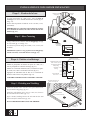
Step 5 - Base Fastening
Using a 5 mm (3/16”) drill bit, drill the tiling ange through
the wall studs (g. 5.1 and g. 5.2).
Fix the base in position using #8 x 32 mm (1 1/4”) screws (not
included).
IMPORTANT: If there is any gap between the tiling ange
and the wall studs, wood shims must be used (g. 5.3).
Étape 6 - Finition et calfeutrage
Installer le placoplâtre en laissant un espace de 6 mm (1/4”)
entre le placoplâtre et la bride de carrelage (g. 6.1).
Installer le revêtement de nition (tuile) en laissant un espace
de 3 mm (1/8”) entre le revêtement et la base (g. 6.1).
Appliquer du calfeutrant entre la base et le revêtement de
nition et entre la base et le plancher (g. 6.2).
ATTENDRE 24 HEURES AVANT D’UTILISER LA DOUCHE.
Step 6 - Finishing and Caulking
Install the drywall; leave a
6 mm (1/4”) space between the
drywall and the tiling ange (g. 6.1).
Install the wall nishing (tile); leave a
3 mm (1/8”) between
the tiles and the shower base (g. 6.1).
Apply a bead of caulking between the tiles and the base and
between the oor and the base (g. 6.2).
WAIT 24 HOURS BEFORE USING THE SHOWER.
Calfeutrant
Caulking
Placoplâtre résistant à l’eau
Water resistant drywall
Revêtement de finition
Wall finishing
heures
heures
hours
hours
24
24
Fig. 6.2
Fig. 6.1
Revêtement de finition
Wall finishing
Placoplâtre résistant à l’eau
Water resistant drywall
Calfeutrant
Caulking
Base de douche
Shower base
Membrane résistante
Water resistant membrane
Montants
Studs
6 mm
(1/4”)
3 mm (1/8”)
Membrane résistante
Water resistant membrane
Étape 5 - Fixation de la base
INSTALLATION EN COIN/CORNER INSTALLATION
À l’aide d’une mèche de 5 mm (3/16”), percer la bride de
carrelage vis-à-vis les montants muraux de l’ossature (g. 5.1
et g. 5.2).
Fixer la base en position à l’aide de vis #8 x 32 mm (1 1/4”)
(non inclus).
IMPORTANT: S’il y a un espace entre la bride de carrelage
et les montants d’ossature, des cales de bois doivent être
utilisées (g. 5.3).

9
102657_RevI
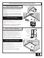
Step 1 - Preparing Framing
The shower base must be installed directly against the studs,
not against the nished wall (g. 1).
IMPORTANT: An additional 2” x 4” stud should be added
to the wall structure to facilitate and strengthen the shower
door installation (g. 1.1).
La base de douche doit être installée directement contre les
montants d’ossature et non contre le mur ni (g. 1).
IMPORTANT : Ajouter un montant d’ossature de 2” x 4”
à la structure pour faciliter et solidier l’installation d’une
porte de douche (g. 1.1).
Fig. 1
Fig. 1.1
Montant 2” x 4” supplémentaire
Additional 2”x4” stud
B
E*
B - 35 mm
(1 3/8’’)
Voir dimensions B et E* selon le modèle de la base à la page 4.
See B and E* dimensions according to the model of the shower base
on page 5.
Step 2 - Plumbing Installation
Mark the drain location. Cut or drill the oor to accommodate
plumbing. The 50 mm (2”) drain pipe should be about 19 mm
(3/4”)* below the oor line (g. 2 and g. 2.1).
*IMPORTANT: The drain dimensions and installation
instructions might vary according to the model of drain used.
Refer to manufacturer’s instructions for proper installation.
Position the base and make sure the draining pipe location
matches the actual location of the shower base drain. Remove
the shower base.
Étape 2 - Installation de la plomberie
d’évacuation
Marquer l’emplacement du drain. Découper ou percer le trou
du drain et installer la plomberie d’évacuation. Le tuyau de
renvoi de 50 mm (2”) doit être à environ 19 mm (3/4”)* sous
le niveau du plancher (g. 2 et g. 2.1).
*IMPORTANT : Les dimensions et instructions d’installation
du drain peuvent varier selon le modèle de drain utilisé.
Consulter les instructions du fabriquant.
Positionner la base et vérier que l’emplacement de la
plomberie d’évacuation est aligné avec le drain de la base.
Retirer la base de douche. Fig. 2
D
C
Installation avec drain à gauche illustrée.
Left-hand drain installation shown.
Voir dimensions C et D selon le modèle de la base à la page 4.
See C and D dimensions according to the model of the shower base
on page 4.
127 mm
(5”) min.
Plancher de béton
Concrete floor
Base
Plancher
de bois
Wood floor
Montants d’ossature
Framing studs
Drain
38 mm (1 1/2”) min.
Fig. 2.1
INSTALLATION EN ALCÔVE/ALCOVE INSTALLATION
Étape 1 - Préparation de l’ossature

10
102657_RevI
Mortier
Mortar
Fig. 4.1
Fig. 4.3
heures
heures
hours
hours
24
24
Mortier
Mortar
Fig. 4.2
Base de douche
Shower base
Calfeutrant
Caulking
Pomelle*
Cover*
Corps du renvoi*
Drain body*
Joints d’étanchéité*
Gaskets*
Écrou du drain*
Drain nut*
Rondelle*
Washer*
Drain non inclus
Drain not included
Fig. 3
Step 3 - Drain Installation
Install the drain* on the shower base according to the
manufacturer’s instructions (g. 3).
*Components might vary according to the model of drain used.
Refer to manufacturer’s instructions for proper installation.
Étape 3 - Installation du drain
Installer le drain* sur la base de douche conformément aux
instructions du fabriquant (g. 3).
* Les composants du drain peuvent varier selon le modèle
utilisé. Consulter les instructions du fabriquant.
Step 4 - Base Installation and Leveling
Spread mortar over the area where the base will be installed
(g. 4.1). Use mortar sold in hardware store. Do not spread
mortar within 127 mm (5”) around the drain area. Lower
the base over the drainage pipe (g. 4.1). Apply pressure to
ensure that the mortar is in contact with the bottom surface
of the base (g. 4.2). IMPORTANT: Make sure the shower
base is leveled (g. 4.3). Complete the drain connection.
IMPORTANT: Make sure the drain is sealed and there is no water
leakage between the base and the drain or below the shower base.
IMPORTANT:
Make sure the drainage is efcient.
WAIT 24 HOURS before proceeding with next step to allow
the tiling anges caulking and the mortar (if applicable) to
harden.
Étape 4 - Installation de la base
et mise à niveau
Mettre du mortier sur la surface d’installation (g. 4.1).
Utiliser le mortier vendu en quincallerie. Ne pas appliquer
de mortier à moins de 127 mm (5”) du trou de drainage.
Déposer la base en alignant le drain et le tuyau de drainage
(g. 4.1). Appuyer sur la base pour que le mortier entre bien en
contact avec la surface sous la base (g. 4.2). IMPORTANT:
Vérier que la base est installée de niveau (g. 4.3).
Compléter le raccordement du drain.
IMPORTANT : S’assurer que le drain est bien scellé et qu’il
n’y ait aucune fuite d’eau entre le drain et la base ou à tout autre
endroit.
IMPORTANT : S’assurer que l’écoulement de l’eau dans
la base se fasse correctement.
ATTENDRE 24 HEURES avant de poursuivre l’installation
de manière à laisser durcir le calfeutrant des brides de
carrelage et à laisser durcir le mortier (si applicable).
INSTALLATION EN ALCÔVE/ALCOVE INSTALLATION

11
102657_RevI
Correct
Fig. 5.1
Fig. 5.3
Montant
Stud
#8 x 32 mm
(1¼”)
Fig. 5.2
Bride de carrelage
Tiling flange
Cales de bois
Wood shims
Membrane résistante
Water resistant membrane
Placoplâtre résistant à l’eau
Water resistant drywall
Revêtement de finition
Wall finishing
heures
heures
hours
hours
24
24
Fig. 6.1
Revêtement de finition
Wall finishing
Placoplâtre résistant à l’eau
Water resistant drywall
Calfeutrant
Caulking
Base de douche
Shower base
Montants
Studs
6 mm
(1/4”)
3 mm (1/8”)
Fig. 6.2
Membrane résistante
Water resistant membrane
INSTALLATION EN ALCÔVE/ALCOVE INSTALLATION
Step 5 - Base Fastening
Using a 5 mm (3/16”) drill bit, drill the tiling ange through
the wall studs (g. 5.1 and g. 5.2).
Fix the base in position using #8 x 32 mm (1 1/4”) screws (not
included).
IMPORTANT: If there is any gap between the tiling ange
and the wall studs, wood shims must be used (g. 5.3).
Étape 6 - Finition et calfeutrage
Installer le placoplâtre en laissant un espace de 6 mm (1/4”)
entre le placoplâtre et la bride de carrelage (g. 6.1).
Installer le revêtement de nition (tuile) en laissant un espace
de 3 mm (1/8”) entre le revêtement et la base (g. 6.1).
Appliquer du calfeutrant entre la base et le revêtement de
nition et entre la base et le plancher (g. 6.2).
ATTENDRE 24 HEURES AVANT D’UTILISER LA DOUCHE.
Step 6 - Finishing and Caulking
Install the drywall; leave a
6 mm (1/4”) space between the
drywall and the tiling ange (g. 6.1).
Install the wall nishing (tile); leave a
3 mm (1/8”) between
the tiles and the shower base (g. 6.1).
Apply a bead of caulking between the tiles and the base and
between the oor and the base (g. 6.2).
WAIT 24 HOURS BEFORE USING THE SHOWER.
Étape 5 - Fixation de la base
À l’aide d’une mèche de 5 mm (3/16”), percer la bride de
carrelage vis-à-vis les montants muraux de l’ossature (g. 5.1
et g. 5.2).
Fixer la base en position à l’aide de vis #8 x 32 mm (1 1/4”)
(non inclus).
IMPORTANT: S’il y a un espace entre la bride de carrelage
et les montants d’ossature, des cales de bois doivent être
utilisées (g. 5.3).

12
102657_RevI
Entretien et nettoyage
Pour éviter les bris et vous assurer d’un fonctionnement
optimal, il est nécessaire de suivre ces recommandations
lors de l’entretien de votre produit Kalia. Les dommages
par un traitement inapproprié ne sont pas couverts par la
garantie Kalia.
- Rincer à l’eau propre et essuyer avec un chiffon de coton
doux ou une éponge. Ne jamais utiliser de matériel abrasif
tel que brosse ou éponge à récurer pour nettoyer les surfaces.
- Pour les souillures tenaces, utiliser un détergent liquide
doux tel que le liquide à vaisselle et de l’eau chaude. Ne pas
utiliser de nettoyant abrasif et acide.
- Lire attentivement l’étiquette du produit de nettoyage an
de vérier qu’il soit adéquat. Toujours essayer la solution
de nettoyage sur une surface moins apparente avant de
l’appliquer sur la totalité de la surface.
- Rincer complètement avec de l’eau immédiatement après
l’application du nettoyant.
- Un nettoyage régulier prévient l’accumulation de saleté et
souillures tenaces.
Maintenance and Cleaning
To avoid damage and optimize your product, you must follow
the below recommendations when maintaining your Kalia
product. Damages resulting from inappropriate handling
are not covered by the Kalia warranty.
- Rinse with clean water and dry with a soft cotton cloth or
sponge. Do not use anything abrasive such as a scouring
brush or sponge to clean the surfaces.
- For tough stains, use a gentle liquid detergent such as dish
soap and hot water. Do not use an abrasive and acidic
cleaner.
- Carefully read the label on the cleaning product to make sure
it is safe and appropriate. Always try the cleaning solution
on a less visible surface before applying it to the rest.
- Completely rinse with water immediately after applying the
cleaner.
- Regular cleaning prevents the accumulation of dirt and
tough stains.

13
102657_RevI
GARANTIE LIMITÉE
Kalia inc. offre la garantie limitée expresse suivante sur ses produits. Cette garantie s’adresse uniquement au propriétaire/utilisateur
original pour un usage personnel domestique et elle débute à la date d’achat du produit. La garantie n’est pas transférable au
propriétaire subséquent. Des restrictions additionnelles s’appliquent aux utilisations commerciales.
GARANTIE 10 ANS LIMITÉE POUR LES BASES EN ACRYLIQUE
Kalia inc. garantit pour 10 ans ses bases en acrylique contre tout défaut de matériel ou de fabrication dans des conditions normales
d’utilisation et d’entretien tant et aussi longtemps que l’acheteur/propriétaire du produit possède sa résidence.
Kalia inc. procédera, à sa discrétion, à la réparation ou au remplacement de pièces, ou du produit trouvé défectueux pour un usage
domestique normal pour lequel il a été conçu.
La présente garantie exclut tout dommage causé en tout ou en partie par des erreurs d’installation, abus d’usage, utilisation non-
conforme, négligence, accident, entretien non-conforme, produits abrasifs.
Kalia inc. n’est aucunement responsable pour tous frais de main-d’œuvre ou tous autres frais reliés à l’installation d’un produit, sa
réparation ou son remplacement ainsi que pour tout dommage ou incident, dépense, perte directe ou indirecte.
Dans tous les cas, Kalia inc., ne peut être tenue responsable de tout montant excédant le prix d’achat du produit qui a été déboursé
par le propriétaire/utilisateur, l’entrepreneur ou le constructeur.
RESTRICTIONS COMMERCIALES
En plus des conditions et restrictions mentionnées ci-dessus, la période de garantie relative à tout produit installé dans le cadre
d’une application commerciale est de un (1) an à compter de la date d’achat originale par le propriétaire/utilisateur, l’entrepreneur
ou le constructeur auprès d’un détaillant autorisé. Si le produit est utilisé en étalage, la période de garantie est d’un (1) an.
SERVICE
Pour se prévaloir du service en vertu de la présente garantie, veuillez communiquer avec Kalia inc., soit par l’entremise de votre
détaillant ou encore directement à nos bureaux à 1-877-GO-KALIA (1-877-465-2542) ou en écrivant à : [email protected]
ou à : Kalia inc., Service à la clientèle, 1355, 2e Rue, Sainte-Marie (Québec) Canada G6E 1G9. Assurez-vous de pouvoir fournir
toute l’information nécessaire concernant votre demande soit : description du problème et du produit, numéro de modèle, la
couleur, le numéro de série, le ni, la date de l’achat, le nom du détaillant en plus de votre facture originale. Pour toute autre
information ou pour connaître un réparateur près de chez vous, n’hésitez pas à nous contacter.
CETTE GARANTIE EST OFFERTE EXCLUSIVEMENT EN LIEU ET PLACE DE TOUTE AUTRE GARANTIE,
Y COMPRIS LES GARANTIES DE QUALITÉ MARCHANDE OU D’APTITUDE DE PRODUIT POUR UNE
APPLICATION PARTICULIÈRE.
Ceci est la garantie originale écrite de Kalia inc.
Garantie

14
102657_RevI
Warranty
LIMITED WARRANTY
Kalia Inc. offers the following express limited warranty on its products. This warranty extend only to the original owner/end-user
for personal household use and are effective as of the date of purchase. The warranty is not transferable to subsequent owners.
Additional limitations may apply for commercial use.
10 YEAR LIMITED WARRANTY ON KALIA ACRYLIC BASES
Kalia Inc. guarantees all aspects of its acrylic bases to be free of defects in material and workmanship for normal residential use
for a period of 10 years and for the original consumer-purchaser of his or her home. If a defect is found during normal residential
use, Kalia Inc. may, at its sole discretion, elect to repair or provide a replacement part or product.
Damage to a product caused by accident, misuse, or abuse is not covered under this warranty. Improper care and cleaning
shall have the effect of rendering this warranty void. Kalia Inc. is not responsible for labor, installation or other incidental or
consequential expenses. Under no circumstances shall the liability of Kalia Inc. exceed the purchase price paid for the product by
the owner/end-user, contractor or builder.
COMMERCIAL LIMITATIONS
In addition to the previously mentioned conditions and limitations, the warranty period for products installed for commercial
applications, or used in commercial ventures, shall cover a period of one (1) year from the initial date of purchase by the owner/
end-user, contractor or builder from an authorized dealer. If the product is sold by Kalia Inc. as a display item, a one (1) year
warranty applies.
WARRANTY SERVICE
If you wish to make a claim under this warranty, you may contact Kalia through your Dealer or directly at 1-877-GO-KALIA
(1-877-465-2542) or again by writing to: [email protected] or to: Kalia Inc., Attn: Customer Service Dept., 1355 2nd Street,
Sainte-Marie (Québec) G6E 1G9 Canada. Be sure to provide all pertinent information related to your claim, including a complete
description of the problem you are experiencing, the product name, product model number, color, nish, and nally the date and
the location where the product was purchased. Also include the product’s serial number or original receipt. For more information
or to obtain the name and address of the service and repair centre nearest you, call 1-877-GO-KALIA.
EXCEPT AS SET FORTH HEREIN, KALIA INC. PROVIDES NO OTHER WARRANTIES, EITHER EXPRESS OR
IMPLIED, INCLUDING IMPLIED WARRANTIES OF FITNESS AND MERCHANTABILITY FOR A PARTICULAR
PURPOSE OR COMPLIANCE WITH ANY CODE.
This is the exclusive written warranty of Kalia Inc.

15
102657_RevI
Notes

Imprimé en Chine/Printed in China 102657_RevI
-
 1
1
-
 2
2
-
 3
3
-
 4
4
-
 5
5
-
 6
6
-
 7
7
-
 8
8
-
 9
9
-
 10
10
-
 11
11
-
 12
12
-
 13
13
-
 14
14
-
 15
15
-
 16
16


dans d''autres langues
- English: Kalia BW1457-240 User guide
Documents connexes

Autres documents
-
MAAX 140009-000-002 CSS40 Guide d'installation
-
MAAX 103006-000-002 32SKD Guide d'installation
-
-
MAAX 105680-000-001 Murmur 5555 Guide d'installation
-
-
MAAX 105456-091-001-001 Guide d'installation
-
-