Bradley Lenox Installation Instructions Manual
- Taper
- Installation Instructions Manual

Installation
P.O. Box 309
Menomonee Falls, WI 53052 USA
800 BRADLEY (800 272 3539)
+1 262 251 6000
bradleycorp.com
Lenox
®
Lockers
Casiers Lenox
®
Casilleros Lenox
®
(includes Cubby & "Z" Lockers)
(comprend les casiers ouverts et « Z »)
(incluye casilleros de cubículos y "Z")
U.S. Patent Nos.
Brevets américains n°
Patente de EE. UU. n.°
6,685,285; 6,792,661; 6,793,299; 7,029,078;
7,223,317; 7,278,695; 7,510,249; 7,699,412;
7,789,471; 8,113,602
LK-INSTR-001 Rev. N; ECN 17-13-005
© 2017 Bradley
Page 1 of 46 10/19/2017
Watch the installation video!
Voir la vidéo d’installation.
Revise el video de instalación.
Table of Contents
Pre-Installation Information ............................. 3
Hardware List ....................................... 4
Optional Locker Base Installation ........................ 5
Optional Corner Filler Installation . . . . . . . . . . . . . . . . . . . . . . . . 6
Locker Installation .................................... 7
Corner Locker Installation .............................. 8
Optional End Filler Installation .......................... 9
Number Plate Installation .............................. 9
Optional Locker Slope Top Installation .................10-11
Optional Locker Flat Top Installation..................... 12
Optional End Panel Installation......................... 13
Back-To-Back Locker Installation ....................... 14
Back-To-Back Locker Slope Top Installation .............15-16
Island End Panel Installation........................... 16
Table des matières
Avant l’installation ................................... 18
Liste de la visserie .................................. 19
Installation de la base de casier en option ................ 20
Installation du panneau d’angle en option ................ 21
Installation des casiers ............................... 22
Installation d’un casier d’angle ......................... 23
Installation du panneau de bout en option ................ 24
Pose des plaques numérotées ......................... 24
Installation du toit incliné de casier en option............25-26
Installation du toit plat de casier en option ................ 27
Installation des panneaux d’extrémité en option............ 28
Installation de casiers dos à dos........................ 29
Installation du toit incliné sur des casiers dos à dos
.........30-31
Installation des panneaux d’extrémité d’îlot ............... 31
Contenido
Información previa a la instalación ...................... 33
Lista de piezas metálicas ............................. 34
Instalación opcional de la base del casillero............... 35
Instalación opcional de la pieza de relleno para esquinas
........ 36
Instalación del casillero............................... 37
Instalación del casillero de esquina ..................... 38
Instalación opcional de la pieza de relleno de los extremos
....... 39
Instalación de la placa de número ...................... 39
Instalación opcional de la parte superior inclinada del casillero
40-41
Instalación opcional de la parte superior plana del casillero .. 42
Instalación opcional del panel del extremo................ 43
Instalación espalda contra espalda de los casilleros ........ 44
Instalación espalda contra espalda de la parte
superior inclinada de los casilleros ....................45-46
Instalación del panel del extremo en isla ................. 46

Lenox
®
Locker (includes Cubby & "Z" Lockers) Installation
2 10/19/2017 Bradley • LK-INSTR-001 Rev. N; ECN 17-13-005
WARNING
All lockers must be either secured against a wall or installed back-to-back (for island configuration).
Lockers and slope top components are extremely heavy and may require more than one person to position
and install.
Failure to comply with these instructions may result in personal injury and/or property damage and will viod
the locker warranty.
NOTICE
Lockers should be installed in a climate-controlled environment and shielded from direct sunlight.
Make sure all floors and walls are clean and smooth. Remove loose impediments, such as protruding nails,
and other debris which could affect installation. The lockers must be square AND level AND floor-supported
or they will not operate properly (a locker that is square may not be level so be sure to check both).
Optional locker base must be square and level, and anchored to the floor before lockers are installed. The
lockers will not operate properly if the base is not square AND level AND not floor-supported. A locker base
that is square may not be level so be sure to check both!
Carefully lift lockers at the base when moving and positioning. Do not drag the lockers!
IMPORTANT
Read this entire installation manual to ensure proper installation. When finished with the installation, file
this manual with the owner or maintenance department. Compliance and conformity to local codes and
ordinances is the responsibility of the installer.
Separate parts from packaging and make sure all parts are accounted for before discarding any packaging
material. If any parts are missing, do not begin installation until you obtain the missing parts.
Review your locker layout drawings and verify the number of lockers and components before beginning
installation.
Standard lockers are shown in most illustrations. Cubby lockers and “Z" lockers are similar and are installed
in the same manner.
Product warranties may be found under "Products" on our web site at www.bradleycorp.com.

Installation Lenox
®
Lockers (includes Cubby & "Z" Lockers)
Bradley • LK-INSTR-001 Rev. N; ECN 17-13-005 10/19/2017 3
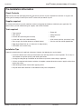
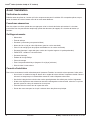
Pre-Installation Information
Check Contents
Separate all parts from packaging materials and ensure you have all parts required for installation. If any parts are
missing, do not attempt to install your Lenox
®
Lockers until you obtain all parts.
Supplies required
For lockers with no base, you will need floor anchors and appropriate hardware suitable for your application. For
optional fillers, you will need blocking (for support) and suitable fasteners.
Tools required
• Tape measure
• 9/32" drill bit
• Hammer drill (for drilling into concrete)
• 6’ level and shims (for standard lockers)
• Pop rivet gun (for number plates on standard lockers)
• Right-Angle Power Drill (for 12" wide and 12" deep lockers)
• OPTIONAL: chalk and/or string
Installation Tips
Properly installed lockers will need little adjustment. However, the following tips may be helpful:
• A chalk line drawn across the top of the locker banks will help provide a visual inspection. This is only an
aid and does not replace squaring and leveling the lockers.
• A string line along the top and bottom of the lockers may also be used to help in alignment.
• If shims are required after locker installation is complete, remove obstructive screws, apply the shims then
replace the screws.
• Avoid twisting the locker frames when applying shims.
• Drill pilot holes when fasteners are threaded into the plastic components.
• Power drill
• Phillips driver bit
• Clamps
• 3/16" masonry drill bit (minimum 6" long)
• Circular saw with carbide-tipped blade

Lenox
®
Locker (includes Cubby & "Z" Lockers) Installation
4 10/19/2017 Bradley • LK-INSTR-001 Rev. N; ECN 17-13-005
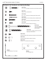
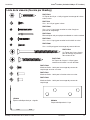
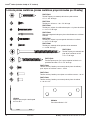
Hardware List (hardware provided by Bradley)
FAST-T349
#10 x 1/2" Lg. screw for base
FAST-LF042
1/4" x 2-1/4" Lg. Tapcon screw for securing
slope top to concrete wall
FAST-LF026
#6 x 1-1/2" Lg. screw for fastening corner locker to filler
FAST-LF029
Black multi-grip rivet for number plate on standard lockers
FAST-LF041
#8 x 1-1/4" Lg. screw for fastening slope top to locker
FAST-LF006
#6 x 5/8" Lg. screw for end panel mounting
FAST-LF032
1/4" x 5" Lg. Tapcon
screw for island locker
floor mounting
FAST-LF031
#10-24 sex bolt for locker-to-locker fastening
FAST-LF044
#10-24 x 1/2" sex bolt for filler mounting
FAST-LF015
1/4" x 1-3/4" Lg. Tapcon screw for base and locker mounting
FAST-LF030
#10-24 sex bolt for filler mounting and locker-to-locker fastening
HW0018
3" Corner Bracket - Zinc Plated
HW0048
2-1/2" Mending Plate

Installation Lenox
®
Lockers (includes Cubby & "Z" Lockers)
Bradley • LK-INSTR-001 Rev. N; ECN 17-13-005 10/19/2017 5
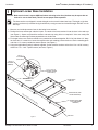
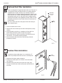
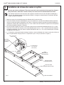
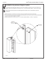
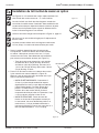
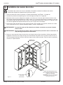
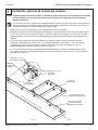
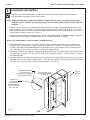
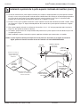
NOTICE! Make sure the base is square AND level before anchoring to the floor (the base may be square but not
level so be sure to check both). This will ensure proper locker operation.
Figure 1
WALL/FLOOR INTERSECTION
END CAP
LOCKER BASE (FOR
WALL-MOUNTED
LOCKERS)
LOCKER BASE (FOR
ISLAND LOCKERS)
1/4 x 1-3/4" LG.
TAPCON SCREW
(FAST-LF015)
ANGLE
BRACKET
(HW0018)
#10-1/2"
LG. SCREW
(FAST-T349)
ISLAND BASE
END CAP
MENDING PLATE
(HW0048)
Optional Locker Base Installation
1
The base sections are shipped in standard lengths and come with slotted end caps. The length of the base
sections can be easily modified during installation by cutting one end to the desired length. DO NOT cut the
end caps.
1. Measure and scribe placement lines for the locker base sections.
2. Position the base sections per submittal layout. The ends of the base sections fit into the slots in the end caps
(see Figure 1). Square and plumb the sections and end caps using shims as required. If shims are used, place
them under the mounting brackets perpendicular to the bracket.
3. For longer locker runs, the base sections may need to be connected together. Drill 1/16" pilot holes 1/2" deep
for the #10 x 1/2" screws that fasten the angle bracket and mending plate to the base. Use the mending plate
and #10 x 1/2" screws provided to connect pieces (see Figure 1).
4. Using the applicable mounting hardware supplied, anchor the base sections to the floor. Use a 3/16" masonry
drill bit for 1/4" x 1-3/4" Tapcon screws (see inset, Figure 1).

Lenox
®
Locker (includes Cubby & "Z" Lockers) Installation
6 10/19/2017 Bradley • LK-INSTR-001 Rev. N; ECN 17-13-005
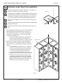
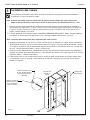
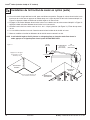
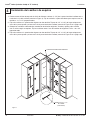
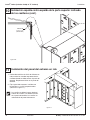
1. Align the filler to the locker top and front and temporarily clamp in place.
2. Using the holes in the filler as a template, drill four 9/32" dia. holes through the locker as shown in Figure 2.
3. Secure the filler to the locker with the #10-24 male and #10-24 x 1/2" female sex bolts provided.
Figure 2
#10-24 SEX
BOLT
(FAST-LF030)
#10-24 x 1/2"
SEX BOLT
(FAST-LF044)
Optional Corner Filler Installation
2
Corner fillers are designed to fill gaps in corners (a corner filler is shown in Figure 3 on page 6). They are
attached to the locker with the #10-24 male and #10-24 x 1/2" female sex bolts provided.
Be sure to attach the filler to the proper side of the locker per your submittal layout.

Installation Lenox
®
Lockers (includes Cubby & "Z" Lockers)
Bradley • LK-INSTR-001 Rev. N; ECN 17-13-005 10/19/2017 7
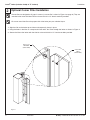
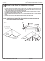
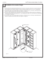
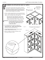
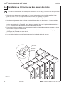
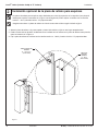
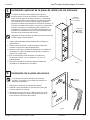
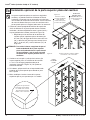
Figure 3
DRILL 3/16" DIA.
PILOT HOLE IN
CONCRETE OR
BLOCK WALL
FILLER
DRILL 9/32" DIA.
CLEARANCE HOLE
THROUGH BACK
OF LOCKER
CENTERLINE
OF LOCKER
BACK
Locker Installation
3
Refer to your submittal layouts for proper locker position. The first locker is usually installed at a corner or at
the end of a run.
NOTICE! Make sure each locker is square AND level before securing into place (the lockers may be square but not
level so be sure to check both). Use shims as needed.
1. Position the first locker according to your submittal layouts. Square and plumb the locker using shims as
required. Secure the locker to the wall in two places with the two 1/4" x 1-3/4" Lg. Tapcon screws. With the
screws centered across the width of the locker, place one near the top and one near the bottom as shown in
Figure 3.
2. Position the second locker next to the first locker. STANDARD LOCKERS ONLY: Square and plumb the locker
using shims (as required) to align the tops and fronts.
NOTICE!
Lockers must be installed flush with adjacent lockers.
3. Temporarily clamp the lockers together at the top and bottom. Drill four 9/32" clearance holes through locker
as shown in Figure 3. The holes should be located 1-1/2" from the front of the locker and evenly spaced, top to
bottom. Fasten lockers to each other using the #10-24 male and #10-24 x 3/4" female sex bolts provided.
4. Position additional lockers according to your submittal layouts. Square and plumb each locker using shims as
required. Fasten lockers to each other using the #10-24 male and #10-24 x 3/4" female sex bolts provided.
5. Secure each locker to the wall in two places with the appropriate wall installation hardware provided. Use two
1/4" x 1-3/4" Lg. Tapcon screws, placing one near the top and one near the bottom of the locker as shown in
Figure 3.

Lenox
®
Locker (includes Cubby & "Z" Lockers) Installation
8 10/19/2017 Bradley • LK-INSTR-001 Rev. N; ECN 17-13-005
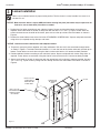
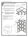
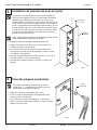
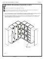
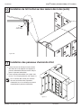
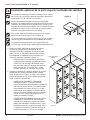
Figure 4
#6 x 1-1/2" LG.
SCREW
(FAST-LF026)
CORNER FILLER
Corner Locker Installation
4
1. Drill four 3/16" dia. clearance holes 1-1/2" from the locker face through the locker box only (see Figure 4).
Fasten the locker to the corner filler with the #6 x 1-1/2" screws provided.
2. Secure each locker to the wall in two places with two 1/4" x 1-3/4" Lg. Tapcon screws, placing one near the top
and one near the bottom of the locker (refer to Figure 3 on page 6).
3. Position the additional lockers according to the submittal layouts. Square and plumb each locker using shims as
required. Fasten the lockers to each other using the #10 x 3/4" T-25 security screws provided.
4. Secure each locker to the wall in two places with two 1/4" x 1-3/4" Lg. Tapcon screws, placing one near the top
and one near the bottom of the locker (see Figure 3 on page 6).

Installation Lenox
®
Lockers (includes Cubby & "Z" Lockers)
Bradley • LK-INSTR-001 Rev. N; ECN 17-13-005 10/19/2017 9
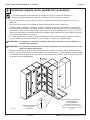
Figure 6
Figure 5
END
FILLER
BLOCKING
(provided by
Installer)
RIVET
(FAST-LF029)
Optional End Filler Installation
5
Fillers are designed to fill gaps between locker runs. They are cut
to size by the installer and attached with 3-4 suitable fasteners
supplied by the installer. The fillers are attached to either an
adjoining locker or blocking (the blocking provides support at the
end of a locker run). If fillers are being attached to a wall, attach
the blocking to the wall first, then secure with suitable fasteners
(blocking and fasteners are supplied by installer). Make sure the
blocking is positioned so that the filler will be flush with the face
with the locker.
Be sure to attach the filler to the proper side of the locker per
your submittal layout.
1. Cut the end locker filler to size.
2. Align the filler to the locker top and front and temporarily clamp
in place.
3. Using the holes in the filler as a template, drill four 9/32" dia.
holes through the locker (refer to Figure 2 on page 5).
4. Secure one side of the filler to the locker with the #10-24 male
and #10-24 x 1/2" female sex bolts provided.
5. Secure the other side of the filler to the blocking (fasteners
provided by installer).
Number Plate Installation
6
Installation of the number plate is for a standard or “Z"
locker only. Cubby locker does not have a number plate.
1. Determine the locker number sequence.
2. Position the number plate in the recess in the locker door
(see Figure 6).
3. Hold the plate in place with your finger and, using a pop
rivet gun, install the two rivets into the plate from the front of
the locker.

Lenox
®
Locker (includes Cubby & "Z" Lockers) Installation
10 10/19/2017 Bradley • LK-INSTR-001 Rev. N; ECN 17-13-005
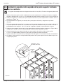
Figure 7a
Figure 7b
WALL STRIP
1-1/4"
Optional Locker Slope Top Installation
7a
Standard 3-tier lockers are shown in Figures 7a–7e. Slope and
flat tops for Cubby and “Z" lockers are similar.
The slope tops are shipped in standard lengths and can be easily
modified during installation. This modification is often necessary
to overcome a variety of installation situations. Use a panel saw
to cut the slope top sections to the proper length if necessary.
Use the corner slope top in the corner as shown in Figure 7c on
page 10.
Corner slope tops should only be trimmed when they extend past
the edge of the locker.
Wall strips will be 54" maximum length. Color of wall strips may
var y.
1. Drill the appropriate number of 3/16" dia. clearance holes
through the top of the installed lockers, making sure
that the holes are located 1-1/4" from the front edge of
the locker. This dimension is critical to ensure proper
installation (see Figure 7a).
• Locker screw hole requirements: slope tops less
than 18" long, two holes; 18"–35" long, three
holes; 36"–45" long, four holes; 72" long, six holes.
2. Position the wall strip (or strips) on top of the lockers
flush against the wall as shown in Figure 7b. Measure,
scribe and drill 1/4" mounting holes into the wall strip as
follows:
• CONCRETE/BLOCK WALLS: Start 1" from each
end and space holes equally (do not exceed 16"
on centers). The holes must be located at least
1-1/4" from the bottom edge of the wall strip.
Use a 3/16" masonry drill bit and 1/4 x 1-3/4" Lg.
Tapcon screws to anchor the wall strip to the wall.
• STUD WALLS: Drill the mounting holes at every
stud location covered by the wall strip. The holes
must be located at least 1-1/4" from the bottom
edge of the wall strip. Anchor the wall strip to the
wall with #14 x 1-3/4" Lg. pan head screws.

Installation Lenox
®
Lockers (includes Cubby & "Z" Lockers)
Bradley • LK-INSTR-001 Rev. N; ECN 17-13-005 10/19/2017 11
WALL
STRIP
1-1/4"
Figure 7c
NOTICE! The Corner Slope Top is shipped flat with a score at the bend. To form the bend, press down at the
score line during installation. DO NOT OVERBEND.
score line
CORNER
SLOPE TOP
Press down along this
line to form the bend
during installation.
CORNER
SLOPE TOP
Install slope top with groove
side facing down
SLOPE TOP
SECTION
#8 x 1-1/4"
SCREW
(FAST-LF041)
1/4" x 2-1/4"
TAPCON SCREW
(FAST-LF042)
Optional Locker Slope Top Installation (continued)
7a
3. If a corner slope top is being installed, position that slope top first. Fit the groove of the slope top over the front
edge of the locker while at the same time pressing down on the score line of the slope top as shown in Figure
7c. Rest the back edge of the corner slope top onto the wall strip.
4. Fit the groove of the next slope top section over the front edge of the locker as shown in Figure 7c. Rest the
back edge of the slope top section onto the wall strip.
5. Secure the slope top to the locker with the #8 x 1-1/4" Lg. screws provided (see Figure 7c). Do not overtighten
screws.
6. If desired, caulk the gap in the back edge of the slope top where it meets the wall strip.
7. Measure, modify and install the remaining slope tops for a custom fit.

Lenox
®
Locker (includes Cubby & "Z" Lockers) Installation
12 10/19/2017 Bradley • LK-INSTR-001 Rev. N; ECN 17-13-005
Figure 7d
Figure 7e
FLAT TOP
Start at the corner and work
outward as shown.
Drill holes equidistant
from locker front to
back.
2" x 2" CORNER
SUPPORT BLOCKING
(supplied by installer).
Make sure the edge of
the flat top with the radius
is facing the front of the
lockers as shown.
Optional Locker Flat Top Installation
7b
The flat tops are shipped in standard lengths and can be
easily modified during installation. This is often necessary
to overcome a variety of installation situations. Use a
panel saw to cut the flat top sections to the proper length if
necessary.
1. Drill the appropriate number of 3/16" dia. clearance holes
through the top of the installed lockers equidistant from
locker front to back (see Figure 7d).
• Locker screw hole requirements: flat tops less than
18" long, two holes; 18"–35" long, three; 36"–45"
long, four; 72" long, six.
CAUTION To prevent injury, make sure the radiused
edge of the flat top is facing the front of the
lockers, and the sharp edge is facing the
back of the lockers.
2. Starting at the corner and working outward, secure
the flat top to the locker with the #8 x 1-1/8" Lg.
screws (provided by installer) (see Figure 7e). Do
not overtighten screws.
3. If desired, caulk the gap in the back edge of the flat
top where it meets the wall.
4. Measure, modify and install the remaining flat tops
for a custom fit.

Installation Lenox
®
Lockers (includes Cubby & "Z" Lockers)
Bradley • LK-INSTR-001 Rev. N; ECN 17-13-005 10/19/2017 13
Figure 8
#6 x 5/8" SCREW
(FAST-LF006)
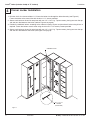
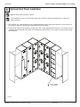
Optional End Panel Installation
8
Optional slope top not shown in Figure 8.
The end panels can be cut to size with a panel saw if necessary. Only the front edge has a radius and
should not be cut.
1. Drill five 3/16" dia. holes through each of the exposed locker side(s) where the end panel is to be attached at
the locations shown in Figure 8. Do not drill holes into the end panel.
2. Fasten the end panel to the locker(s) using the #6 x 5/8" screws provided (see Figure 8). The screws must be
inserted through the inside of the locker and screwed into the end panel. The screws will not protrude through
the end panel.

Lenox
®
Locker (includes Cubby & "Z" Lockers) Installation
14 10/19/2017 Bradley • LK-INSTR-001 Rev. N; ECN 17-13-005
Figure 9
FILLER
9/32" DIA. CLEARANCE
HOLE THROUGH LOCKER
BOTTOM INTO FLOOR
Drill 3/16" dia. pilot hole
through locker bottom in
concrete floor.
1/4" x 5" LG. TAPCON
SCREW (FAST-LF032)
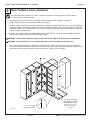
Back-To-Back Locker Installation
9
Back-to-back locker installation is similar to standard installation. The base sections must be square
and plumb prior to installing lockers.
1. Anchor the base sections to the floor using the hardware supplied (refer to Step 1 on page 4).
2. Fasten fillers to the corner lockers (refer to Step 2 on page 5).
3. Position, square and plumb the lockers onto the base, making sure locker tops and fronts are flush. Temporarily
clamp the adjoining locker sides together at the top and bottom. Drill four 9/32" holes through locker. The holes
should be located 1-1/2" from the front of the locker and evenly spaced from top to bottom (refer to Figures 3a
and 3b on page 6 if necessary).
4. Drill four 9/32" holes through one adjoining locker back (see Figure 9). Fasten the lockers together using the
#10-24 male and #10-24 x 3/4" female sex bolts provided.
WARNING Island locker installation requires floor mounting in addition to locker-to-locker attachment.
WARNING For concrete floors, use a hammer drill with a six-inch long drill bit for pilot holes.
5. Drill a 3/16" pilot hole through the bottom of each locker into the floor. Use a drill with a six-inch long drill bit.
The holes should be located near the front of the locker. Drill a 9/32" clearance hole through the bottom of each
locker into the floor. Secure the lockers to the floor with the Tapcon screws provided.

Installation Lenox
®
Lockers (includes Cubby & "Z" Lockers)
Bradley • LK-INSTR-001 Rev. N; ECN 17-13-005 10/19/2017 15
Figure 10a
ANGLE
BRACKET
(HW0019)
#10-1/2"
LG. SCREW
(FAST-T349)
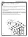
Back-To-Back Locker Slope Top Installation
10
Mounting strips will be 54" maximum length. Color of strips may vary.
1. Drill 3/16" dia. clearance holes through the top of the installed lockers, making sure that the holes are located
1-1/4" from the front edge of the locker (see Figure 7a on page 9).
2. Position the slope top mounting strips on top of the lockers as shown in Figure 10a.
3. Temporarily clamp the slope top mounting strips together, making sure they are flush and aligned.
4. Using the 2" mounting brackets and hardware supplied, anchor the mounting strips to the top of the locker as
shown in Figure 10a. Drill 1/16" pilot holes 1/2" deep for the #10 x 1/2" screws that fasten the angle bracket and
mending plate to the base.
5. Position the slope top on top of the lockers as shown in Figure 10b on page 15, fitting the slope top groove over
the edge of the locker.
6. Hold the slope top down tight against the top of the locker and secure with the #8 x 1-1/4" screws provided (see
Figure 10b). Do not overtighten the screws.
7. Install the remaining slope top sections per the instructions outlined above.
8. If desired, caulk the gap in the back edge of the slope top where it meets the wall strip.

Lenox
®
Locker (includes Cubby & "Z" Lockers) Installation
16 10/19/2017 Bradley • LK-INSTR-001 Rev. N; ECN 17-13-005
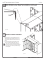
1. Drill ten 3/16" dia. holes through each of the
exposed locker sides where the end panel is
to be attached. Do not drill holes into the end
panel.
2. Fasten the end panel to the locker with the
#6 x 5/8" screws provided (see Figure 11).
Figure 11
Figure 10b
#8 x 1-1/4"
SCREW
(FAST-LF041)
Back-To-Back Locker Slope Top Installation (continued)
10
Island End Panel Installation
11
The screws must be inserted through the
inside of the locker and screwed into the end
panel. The screws will not protrude through
the end panel.

Installation Lenox
®
Lockers (includes Cubby & "Z" Lockers)
Bradley • LK-INSTR-001 Rev. N; ECN 17-13-005 10/19/2017 17
AVERTISSEMENT
Tous les casiers doivent être fixés contre un mur ou installés dos à dos (configuration en îlot).
Les pièces des casiers et des toits inclinés sont très lourdes et peuvent nécessiter plus d’une personne
pour les mettre en place et les monter.
Tout manquement à respecter ces instructions peut entraîner des blessures corporelles ou des dégâts
matériels et invalide la garantie des casiers.
AVIS
Les casiers doivent être installés dans un environnement contrôlé et protégé du soleil.
Vérifier que le sol et les murs sont propres et lisses. Éliminer les obstacles tels que les clous qui dépassent
et autres débris lâches susceptibles d’entraver la pose. Les casiers doivent être d’équerre ET de niveau ET
soutenus par le plancher sinon ils ne fonctionnent pas correctement (un casier d’équerre peut ne pas être
de niveau, veiller donc à vérifier les deux).
La base de casier en option doit être d’équerre, de niveau et ancrée au plancher avant le montage des
casiers. Les casiers ne fonctionnent pas correctement si la base n’est pas d’équerre et de niveau et si elle
n’est pas soutenue par le plancher. Une base de casier qui est d’équerre peut ne pas être de niveau, veiller
donc à vérifier les deux!
Soulever les casiers avec précaution par la base pour les déplacer et les mettre en place. Ne pas traîner les
casiers sur le plancher!
IMPORTANTE
Lire ce manuel d’installation dans son intégralité pour garantir une installation appropriée. Une fois celle-ci
terminée, classer ce manuel auprès du service à la clientèle ou d’entretien. L’installateur est responsable de
respecter la conformité aux codes et ordonnances locaux.
Déballer les pièces et s’assurer qu’elles sont toutes présentes avant de jeter les emballages. Le cas échéant,
ne pas commencer l’installation avant d’avoir obtenu toutes les pièces manquantes.
Examiner les plans d’installation des casiers pour vérifier le nombre de casiers et de composants avant de
procéder à l’installation.
La majorité des illustrations montrent des casiers standards. Les casiers ouverts et les casiers « Z » sont
semblables et s’installent de la même manière.
Les garanties de produit figurent sous « Products » sur notre site Web à l’adresse www.bradleycorp.com.

Lenox
®
Locker (includes Cubby & "Z" Lockers) Installation
18 10/19/2017 Bradley • LK-INSTR-001 Rev. N; ECN 17-13-005
Avant l’installation
Vérification du contenu
Déballer toutes les pièces et s’assurer qu’il n’en manque aucune pour l’installation. S’il manque des pièces, ne pas
tenter de monter les casiers Lenox
®
avant de les avoir toutes obtenues.
Fournitures nécessaires
Pour les casiers sans base, prévoir des ancrages pour sol et la visserie de fixation qui convient à la situation
particulière. Pour les panneaux de remplissage, prévoir des fourrures (de support) et la visserie de fixation qui
convient.
Outillage nécessaire
• Mètre-ruban
• Foret de 9/32 po
• Perceuse à percussion (pour percer le béton)
• Niveau de 1,8 m (6 pi) et cales d’épaisseur (pour les casiers standards)
• Pince à rivet aveugle (pour les plaques numérotées sur les casiers standards)
• Perceuse électrique à angle droit (pour casiers de 12 po de largeur et 12 po de profondeur)
• FACULTATIF : cordeau à craie et/ou ficelle
• Perceuse électrique
• Embout de vissage Phillips
• Pinces de serrage
• Foret à maçonnerie de 3/16 po (longueur 15 cm [6 po] minimum)
• Scie circulaire à lame carbure
Conseils d’installation
Des casiers correctement installés nécessitent peu d’ajustement. Toutefois, les conseils suivants peuvent s’avérer utiles :
• Un trait tracé au cordeau le long du dessus de la rangée de casiers facilitera l’inspection visuelle. Cela est
utile mais ne remplace pas la nécessité de monter les casiers d’équerre et de niveau.
• Une ficelle le long du haut et du bas des casiers peut également être utilisée pour faciliter l’alignement.
• Si des cales d’épaisseur sont nécessaires une fois le montage des casiers terminé, retirer les vis qui font
obstacle, poser les cales puis remettre les vis en place.
• Éviter de vriller les casiers lors de la pose des cales.
• Percer des avant-trous pour les vis qui à enfoncer dans des pièces en plastique.

Installation Lenox
®
Lockers (includes Cubby & "Z" Lockers)
Bradley • LK-INSTR-001 Rev. N; ECN 17-13-005 10/19/2017 19
Liste de la visserie (fournie par Bradley)
FAST-T349
Vis n° 10 x 1/2 po lg pour la base
FAST-LF042
Vis Tapcon de 1/4 po x 2-1/4 po lg pour
attacher le toit incliné à un mur de béton
FAST-LF026
Vis n° 6 x 1-1/2 po lg pour attacher le casier d’angle au
panneau de remplissage
FAST-LF029
Rivet multiprise noir pour plaque numérotée sur casier standard
FAST-LF041
Vis n° 8 x 1-1/4 po lg pour attacher le toit incliné au casier
FAST-LF006
Vis n° 6 x 5/8 po lg pour le montage du panneau de bout
FAST-LF032
Vis Tapcon de 1/4 po x 5 po lg
pour le montage au plancher
des casiers en îlot
FAST-LF031
Manchon fileté n° 10-24 pour la fixation casier sur casier
FAST-LF044
Manchon fileté n° 10-24 pour le montage de panneau de
remplissage
FAST-LF015
Vis Tapcon de 1/4 po x 1-3/4 po lg pour le montage de la base
et des casiers
FAST-LF030
Manchon fileté n° 10-24 pour le montage de panneau de
remplissage et casier sur casier
HW0018
Équerre métallique de 3 po - zinguée
HW0048
Plaque métallique de 2-1/2 po

Lenox
®
Locker (includes Cubby & "Z" Lockers) Installation
20 10/19/2017 Bradley • LK-INSTR-001 Rev. N; ECN 17-13-005
AVIS! S’assurer que la base est d’équerre ET de niveau avant de l’ancrer au plancher (la base peut être d’équerre
mais pas de niveau, veiller donc à vérifier les deux). Cela assurera le bon fonctionnement des casiers.
Installation de la base de casier en option
1
Les éléments de la base sont livrés dans des longueurs standard et fournis avec des pièces d’extrémité à
rainures. Ces éléments peuvent aisément être coupés à la longueur souhaitée durant l’installation. NE PAS
couper les pièces d’extrémité.
1. Mesurer et tracer les traits de pose pour les éléments de la base de casiers.
2. Placer les éléments de base conformément au plan de soumission. Les bouts des éléments de base passent
dans les rainures des pièces d’extrémité (voir Figure 1). Mettre les éléments et pièces d’extrémité d’équerre et
d’aplomb en utilisant des cales d’épaisseur s’il y a lieu. Si des cales sont utilisées, les placer sous les équerres
de fixation perpendiculairement à l’équerre.
3. Pour les longues rangées de casiers, il peut être nécessaire de raccorder des éléments de base l’un à l’autre.
Percer des avant-trous de 1/16 po et 1/2 po de profondeur pour les vis n° 10 x 1/2 po de fixation des équerres
et plaques métalliques à la base. Utiliser la plaque métallique et des vis n° 10 x 1/2 po fournies pour raccorder
les éléments (voir Figure 1).
4. 4. À l’aide de la visserie de fixation fournie qui convient, ancrer les éléments de la base au plancher. Utiliser un
foret à maçonnerie de 3/16 po pour les vis Tapcon de 1/4 po x 1-3/4 po (voir encart, Figure 1).
Figure 1
INTERSECTION MUR/PLANCHER
PIÈCE D’EXTRÉMITÉ
BASE DE CASIER
(CASIERS FIXÉS AU MUR)
BASE DE CASIER
(CASIERS EN ÎLOT)
VIS TAPCON DE
1/4 x 1-3/4" LG
(FAST-LF015)
ÉQUERRE
MÉTALLIQUE
(HW0018)
VIS n° 10-1/2" LG
(FAST-T349)
PIÈCE
D’EXTRÉMITÉ
DE BASE D’ÎLOT
PLAQUE
MÉTALLIQUE
(HW0048)
La page est en cours de chargement...
La page est en cours de chargement...
La page est en cours de chargement...
La page est en cours de chargement...
La page est en cours de chargement...
La page est en cours de chargement...
La page est en cours de chargement...
La page est en cours de chargement...
La page est en cours de chargement...
La page est en cours de chargement...
La page est en cours de chargement...
La page est en cours de chargement...
La page est en cours de chargement...
La page est en cours de chargement...
La page est en cours de chargement...
La page est en cours de chargement...
La page est en cours de chargement...
La page est en cours de chargement...
La page est en cours de chargement...
La page est en cours de chargement...
La page est en cours de chargement...
La page est en cours de chargement...
La page est en cours de chargement...
La page est en cours de chargement...
La page est en cours de chargement...
La page est en cours de chargement...
-
 1
1
-
 2
2
-
 3
3
-
 4
4
-
 5
5
-
 6
6
-
 7
7
-
 8
8
-
 9
9
-
 10
10
-
 11
11
-
 12
12
-
 13
13
-
 14
14
-
 15
15
-
 16
16
-
 17
17
-
 18
18
-
 19
19
-
 20
20
-
 21
21
-
 22
22
-
 23
23
-
 24
24
-
 25
25
-
 26
26
-
 27
27
-
 28
28
-
 29
29
-
 30
30
-
 31
31
-
 32
32
-
 33
33
-
 34
34
-
 35
35
-
 36
36
-
 37
37
-
 38
38
-
 39
39
-
 40
40
-
 41
41
-
 42
42
-
 43
43
-
 44
44
-
 45
45
-
 46
46


Bradley Lenox Installation Instructions Manual
- Taper
- Installation Instructions Manual
dans d''autres langues
- English: Bradley Lenox
- español: Bradley Lenox
Documents connexes
Autres documents
-
 CEMONJARDIN 91090240 Mode d'emploi
-
 NewAge Products 50322 Guide d'installation
-
 NewAge Products 50011 Manuel utilisateur
-
 NewAge Products 56107 Mode d'emploi
-
Gladiator GASL1UKYDG Mode d'emploi
-
 NewAge Products 52380 Guide d'installation
-
 NewAge Products 54368 Guide d'installation
-
 NewAge Products 52298 Manuel utilisateur
-
 NewAge Products 53255 Mode d'emploi
-
Master Lock 1636MKADABLU Mode d'emploi


