ASROCK P55 DELUXE3 Le manuel du propriétaire
- Catégorie
- Cartes mères
- Taper
- Le manuel du propriétaire
Ce manuel convient également à

11
11
1
ASRock P55 Deluxe3 Motherboard
EnglishEnglish
EnglishEnglish
English
Copyright Notice:Copyright Notice:
Copyright Notice:Copyright Notice:
Copyright Notice:
No part of this installation guide may be reproduced, transcribed, transmitted, or trans-
lated in any language, in any form or by any means, except duplication of documen-
tation by the purchaser for backup purpose, without written consent of ASRock Inc.
Products and corporate names appearing in this guide may or may not be registered
trademarks or copyrights of their respective companies, and are used only for identifica-
tion or explanation and to the owners’ benefit, without intent to infringe.
Disclaimer:Disclaimer:
Disclaimer:Disclaimer:
Disclaimer:
Specifications and information contained in this guide are furnished for informational
use only and subject to change without notice, and should not be constructed as a
commitment by ASRock. ASRock assumes no responsibility for any errors or omissions
that may appear in this guide.
With respect to the contents of this guide, ASRock does not provide warranty of any kind,
either expressed or implied, including but not limited to the implied warranties or
conditions of merchantability or fitness for a particular purpose. In no event shall
ASRock, its directors, officers, employees, or agents be liable for any indirect, special,
incidental, or consequential damages (including damages for loss of profits, loss of
business, loss of data, interruption of business and the like), even if ASRock has been
advised of the possibility of such damages arising from any defect or error in the guide
or product.
This device complies with Part 15 of the FCC Rules. Operation is subject to the
following two conditions:
(1) this device may not cause harmful interference, and
(2) this device must accept any interference received, including interference that
may cause undesired operation.
CALIFORNIA, USA ONLY
The Lithium battery adopted on this motherboard contains Perchlorate, a toxic
substance controlled in Perchlorate Best Management Practices (BMP) regulations
passed by the California Legislature. When you discard the Lithium battery in
California, USA, please follow the related regulations in advance.
“Perchlorate Material-special handling may apply, see
www.dtsc.ca.gov/hazardouswaste/perchlorate”
ASRock Website: http://www.asrock.com
Published January 2010
Copyright©2010 ASRock INC. All rights reserved.

22
22
2
ASRock P55 Deluxe3 Motherboard
EnglishEnglish
EnglishEnglish
English
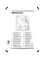
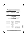
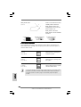
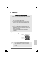
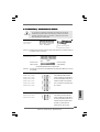
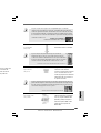
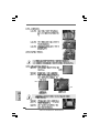
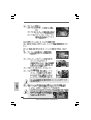
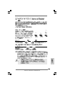
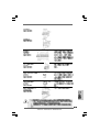
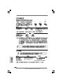
Motherboard LayoutMotherboard Layout
Motherboard LayoutMotherboard Layout
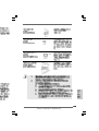
Motherboard Layout
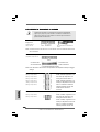
1 PS2_USB_PWR1 Jumper 24 Chassis Intrusion Header (CI1)
2 Power Fan Connector (PWR_FAN1) 25 Reset Switch (RSTBTN)
3 ATX 12V Power Connector (ATX12V1) 26 Power Switch (PWRBTN)
4 1156-Pin CPU Socket 27 Dr. Debug (LED)
5 CPU Fan Connector (CPU_FAN1) 28 Power LED Header (PLED1)
6 2 x 240-pin DDR3 DIMM Slots 29 USB 2.0 Header (USB6_7, Blue)
(Dual Channel: DDR3_A2, DDR3_B2, Blue) 30 Infrared Module Header (IR1)
7 2 x 240-pin DDR3 DIMM Slots 31 USB 2.0 Header (USB4_5, Blue)
(Dual Channel: DDR3_A1, DDR3_B1, White) 32 USB 2.0 Header (USB8_9, Blue)
8 TPM Header (TPM1) 33 Clear CMOS Jumper (CLRCMOS1)
9 Chassis Fan Connector (CHA_FAN1) 34 Front Panel IEEE 1394 Header
10 ATX Power Connector (ATXPWR1) (FRONT_1394, White)
11 SATA3 Connector (SATA3_1, White) 35 COM Port Header (COM1)
12 SATA3 Connector (SATA3_2, White) 36 Floppy Connector (FLOPPY1)
13 Chassis Fan Connector (CHA_FAN2) 37 HDMI_SPDIF Header
14 Primary IDE Connector (IDE1, Blue) (HDMI_SPDIF1, White)
15 SATAII Connector (SATAII_2, Blue ) 38 Front Panel Audio Header
16 SATAII Connector (SATAII_1, Blue ) 39 Internal Audio Connector: CD1 (Black)
17 SATAII Connector (SATAII_4, Blue ) 40 PCI Slots (PCI1-2)
18 SATAII Connector (SATAII_3, Blue ) 41 PCI Express 2.0 x16 Slot (PCIE4, Blue)
19 16Mb SPI Flash 42 PCI Express 2.0 x1 Slot (PCIE3, White)
20 SATAII Connector (SATAII_5, Blue ) 43 Intel P55 Chipset
21 SATAII Connector (SATAII_6, Blue ) 44 PCI Express 2.0 x16 Slot (PCIE2, Blue)
22 Chassis Speaker Header (SPEAKER 1, White) 45 PCI Express 2.0 x1 Slot (PCIE1, White)
23 System Panel Header (PANEL1, White) 46 Chassis Fan Connector (CHA_FAN2)

33
33
3
ASRock P55 Deluxe3 Motherboard
EnglishEnglish
EnglishEnglish
English
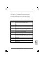
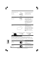
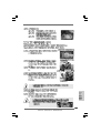
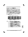
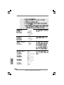
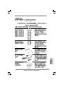
I/O PI/O P
I/O PI/O P
I/O P
anelanel
anelanel
anel
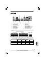
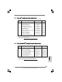
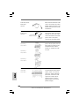
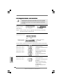
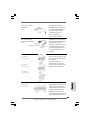
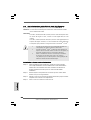
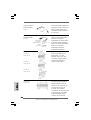
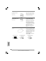
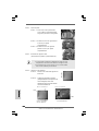
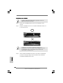
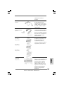
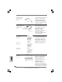
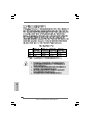
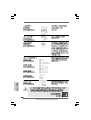
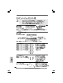
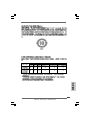
** If you use 2-channel speaker, please connect the speaker’s plug into “Front Speaker Jack”.
See the table below for connection details in accordance with the type of speaker you use.
TABLE for Audio Output Connection
Audio Output Channels Front Speaker Rear Speaker Central / Bass Side Speaker
(No. 10) (No. 7) (No. 8) (No. 6)
2 V -- -- --
4VV----
6 VVV--
8 VVVV
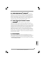
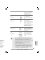
LAN Port
ACT/LINK
LED
SPEED
LED
* There are two LED next to the LAN port. Please refer to the table below for the LAN port LED
indications.
LAN Port LED Indications
Activity/Link LED SPEED LED
Status Description Status Description
Off No Link Off 10Mbps connection
Blinking Data Activity Orange 100Mbps connection
On Link Green 1Gbps connection
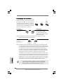
1 PS/2 Mouse Port (Green) ** 10 Front Speaker (Lime)
2 Coaxial SPDIF Out Port 11 Microphone (Pink)
3 USB 2.0 Port (USB12) 12 USB 3.0 Ports
4 IEEE 1394 Port (IEEE 1394) 13 USB 2.0 Ports (USB23)
* 5 LAN RJ-45 Port 14 USB 2.0 Ports (USB01)
6 Side Speaker (Gray) 15 Powered eSATAIII/USB 2.0 Connector
7 Rear Speaker (Black) 16 Optical SPDIF Out Port
8 Central / Bass (Orange) 17 Clear CMOS Switch (CLRCBTN)
9 Line In (Light Blue) 18 PS/2 Keyboard Port (Purple)

44
44
4
ASRock P55 Deluxe3 Motherboard
EnglishEnglish
EnglishEnglish
English
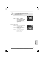
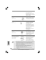
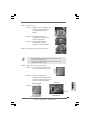
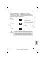
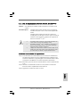
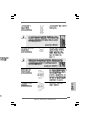
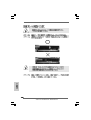
To enable Multi-Streaming function, you need to connect a front panel audio cable to the front
panel audio header. After restarting your computer, you will find “VIA HD Audio Deck” tool on
your system. Please follow below instructions according to the OS you install.
For Windows
®
XP / XP 64-bit OS:
Please click “VIA HD Audio Deck” icon. Click “Jack” and then click “Configuration”. In
“Configuration” screen, please check the item “Independent Headphone”.
For Windows
®
7 / 7 64-bit / Vista
TM
/ Vista
TM
64-bit OS:
Please click “VIA HD Audio Deck” icon. Click “Advanced Options” on the right side on the
bottom. In “Advanced Options” screen, please check the item “Independent Headphone”.

55
55
5
ASRock P55 Deluxe3 Motherboard
1. Introduction1. Introduction
1. Introduction1. Introduction
1. Introduction
Thank you for purchasing ASRock P55 Deluxe3 motherboard, a reliable motherboard
produced under ASRock’s consistently stringent quality control. It delivers excellent
performance with robust design conforming to ASRock’s commitment to quality and
endurance.
This Quick Installation Guide contains introduction of the motherboard and step-by-step
installation guide. More detailed information of the motherboard can be found in the user
manual presented in the Support CD.
Because the motherboard specifications and the BIOS software might
be updated, the content of this manual will be subject to change without
notice. In case any modifications of this manual occur, the updated
version will be available on ASRock website without further notice. You
may find the latest VGA cards and CPU support lists on ASRock website
as well. ASRock website http://www.asrock.com
If you require technical support related to this motherboard, please visit
our website for specific information about the model you are using.
www.asrock.com/support/index.asp
1.1 Package Contents1.1 Package Contents
1.1 Package Contents1.1 Package Contents
1.1 Package Contents
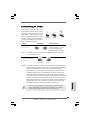
ASRock P55 Deluxe3 Motherboard
(ATX Form Factor: 12.0-in x 9.6-in, 30.5 cm x 24.4 cm)
ASRock P55 Deluxe3 Quick Installation Guide
ASRock P55 Deluxe3 Support CD
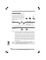
1 x 80-conductor Ultra ATA 66/100/133 IDE Ribbon Cable
1 x Ribbon Cable for a 3.5-in Floppy Drive
4 x Serial ATA (SATA) Data Cables (Optional)
2 x Serial ATA (SATA) HDD Power Cables (Optional)
1 x I/O Panel Shield
1 x ASRock SLI_Bridge_2S Card
EnglishEnglish
EnglishEnglish
English

66
66
6
ASRock P55 Deluxe3 Motherboard
EnglishEnglish
EnglishEnglish
English
1.21.2
1.21.2
1.2
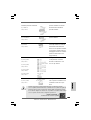
SpecificationsSpecifications
SpecificationsSpecifications
Specifications
Platform - ATX Form Factor: 12.0-in x 9.6-in, 30.5 cm x 24.4 cm
- All Solid Capacitor design (100% Japan-made high-quality
Conductive Polymer Capacitors)
CPU - Supports Intel
®
Core
TM
i7 / i5 / i3 and Pentium
®
G6950
Processors in LGA1156 Package
- Advanced V8 + 2 Power Phase Design
- Supports Intel
®
Turbo Boost Technology
- Supports Hyper-Threading Technology (see CAUTION 1)
- Supports Untied Overclocking Technology (see CAUTION 2)
- Supports EM64T CPU
Chipset - Intel
®
P55
Memory - Dual Channel DDR3 Memory Technology (see CAUTION 3)
- 4 x DDR3 DIMM slots
- Supports DDR3 2600+(OC)/2133(OC)/1866(OC)/1600/
1333/1066 non-ECC, un-buffered memory
- Max. capacity of system memory: 16GB (see CAUTION 4)
- Supports Intel
®
Extreme Memory Profile (XMP)
(see CAUTION 5)
Expansion Slot - 2 x PCI Express 2.0 x16 slots
(Single at x16 or Dual at x8/x8 mode)
- 2 x PCI Express 2.0 x1 slots (2.5GT/s)
- 2 x PCI slots
- Supports ATI
TM
CrossFireX
TM
and Quad CrossFireX
TM
- Supports NVIDIA
®
SLI
TM
and Quad SLI
TM
Audio - 7.1 CH HD Audio with Content Protection
- DAC with 110dB dynamic range (VIA
®
VT2020 Audio Codec)
- Premium Blu-ray audio support
LAN - PCIE x1 Gigabit LAN 10/100/1000 Mb/s
- Realtek RTL8111DL
- Supports Wake-On-LAN
Rear Panel I/O I/O Panel
- 1 x PS/2 Mouse Port
- 1 x PS/2 Keyboard Port
- 1 x Coaxial SPDIF Out Port
- 1 x Optical SPDIF Out Port
- 5 x Ready-to-Use USB 2.0 Ports
- 1 x Powered eSATAIII/USB 2.0 Connector
- 2 x Ready-to-Use USB 3.0 Ports
- 1 x RJ-45 LAN Port with LED (ACT/LINK LED and SPEED LED)

77
77
7
ASRock P55 Deluxe3 Motherboard
EnglishEnglish
EnglishEnglish
English
- 1 x IEEE 1394 Port
- 1 x Clear CMOS Switch with LED
- HD Audio Jack: Side Speaker/Rear Speaker/Central/Bass/
Line in/Front Speaker/Microphone (see CAUTION 6)
SATA3 - 2 x SATA3 6.0Gb/s connectors by Marvell SE9128, support
hardware RAID (RAID 0 and RAID 1), NCQ, AHCI and “Hot
Plug” functions (SATA3_2 connector is shared with eSATA3
port)
USB3.0 - 2 x USB3.0 ports by NEC UPD720200, support USB 1.0/2.0/
3.0 up to 5Gb/s
Connector - 6 x SATAII 3.0Gb/s connectors, support RAID (RAID 0,
RAID 1, RAID 10, RAID 5 and Intel Rapid Storage), NCQ,
AHCI and “Hot Plug” functions
- 2 x SATA3 6.0Gb/s connectors
- 1 x ATA133 IDE connector (supports 2 x IDE devices) (Please
use bundled 80-conductor IDE cable)
- 1 x Floppy connector
- 1 x IR header
- 1 x COM port header
- 1 x HDMI_SPDIF header
- 1 x IEEE 1394 header
- 1 x TPM header
- 1 x Chassis Intrusion header
- 1 x Power LED header
- CPU/Chassis/Power FAN connector
- 24 pin ATX power connector
- 8 pin 12V power connector
- CD in header
- Front panel audio connector
- 3 x USB 2.0 headers (support 6 USB 2.0 ports)
(see CAUTION 7)
- 1 x Dr. Debug (7-Segment Debug LED)
Smart Switch - 1 x Clear CMOS Switch with LED
- 1 x Power Switch with LED
- 1 x Reset Switch with LED
BIOS Feature - 16Mb AMI BIOS
- AMI Legal BIOS
- Supports “Plug and Play”
- ACPI 1.1 Compliance Wake Up Events
- Supports jumperfree
- SMBIOS 2.3.1 Support

88
88
8
ASRock P55 Deluxe3 Motherboard
EnglishEnglish
EnglishEnglish
English
WARNING
Please realize that there is a certain risk involved with overclocking, including adjusting
the setting in the BIOS, applying Untied Overclocking Technology, or using the third-
party overclocking tools. Overclocking may affect your system stability, or even
cause damage to the components and devices of your system. It should be done at
your own risk and expense. We are not responsible for possible damage caused by
overclocking.
- CPU, VCCM, SB, VTT, PCH PLL Voltage Multi-adjustment
- Supports I. O. T. (Intelligent Overclocking Technology)
Support CD - Drivers, Utilities, AntiVirus Software (Trial Version),
ASRock Software Suite (CyberLink DVD Suite and Creative
Sound Blaster X-Fi MB) (OEM and Trial Version)
Unique Feature - ASRock OC Tuner (see CAUTION 8)
- Intelligent Energy Saver (see CAUTION 9)
- Instant Boot
- ASRock Instant Flash (see CAUTION 10)
- ASRock OC DNA (see CAUTION 11)
- Hybrid Booster:
- CPU Frequency Stepless Control (see CAUTION 12)
- ASRock U-COP (see CAUTION 13)
- Boot Failure Guard (B.F.G.)
- Combo Cooler Option (C.C.O.) (see CAUTION 14)
- Good Night LED
Hardware - CPU Temperature Sensing
Monitor - Chassis Temperature Sensing
- CPU/Chassis/Power Fan Tachometer
- CPU Quiet Fan
- CPU/Chassis Fan Multi-Speed Control
- CASE OPEN detection
- Voltage Monitoring: +12V, +5V, +3.3V, CPU Vcore
OS - Microsoft
®
Windows
®
7 / 7 64-bit / Vista
TM
/ Vista
TM
64-bit
/ XP / XP 64-bit compliant
Certifications - FCC, CE, WHQL
- EuP Ready (EuP ready power supply is required)
(see CAUTION 15)
* For detailed product information, please visit our website: http://www.asrock.com

99
99
9
ASRock P55 Deluxe3 Motherboard
EnglishEnglish
EnglishEnglish
English
CAUTION!
1. About the setting of “Hyper Threading Technology”, please check page 60
of “User Manual” in the support CD.
2. This motherboard supports Untied Overclocking Technology. Please read
“Untied Overclocking Technology” on page 35 for details.
3. This motherboard supports Dual Channel Memory Technology. Before you
implement Dual Channel Memory Technology, make sure to read the
installation guide of memory modules on page 15 for proper installation.
4. Due to the operating system limitation, the actual memory size may be
less than 4GB for the reservation for system usage under Windows
®
7 /
Vista
TM
/ XP. For Windows
®
XP 64-bit and Windows
®
OS with 64-bit CPU,
there is no such limitation.
5. For those CPU that only support up to DDR3 1333, the XMP DDR3 1600
is supported through overclocking.
6. For microphone input, this motherboard supports both stereo and mono
modes. For audio output, this motherboard supports 2-channel, 4-channel,
6-channel, and 8-channel modes. Please check the table on page 3 for
proper connection.
7. Power Management for USB 2.0 works fine under Microsoft
®
Windows
®
7
64-bit / 7 / Vista
TM
64-bit / Vista
TM
/ XP 64-bit / XP SP1 or SP2.
8. It is a user-friendly ASRock overclocking tool which allows you to surveil
your system by hardware monitor function and overclock your hardware
devices to get the best system performance under Windows
®
environment.
Please visit our website for the operation procedures of ASRock OC
Tuner.
ASRock website: http://www.asrock.com/feature/OCTuner/index.htm
9. Featuring an advanced proprietary hardware and software design,
Intelligent Energy Saver is a revolutionary technology that delivers
unparalleled power savings. In other words, it is able to provide exceptional
power saving and improve power efficiency without sacrificing computing
performance. Please visit our website for the operation procedures of
Intelligent Energy Saver.
ASRock website: http://www.asrock.com/feature/IES/index.html
10. ASRock Instant Flash is a BIOS flash utility embedded in Flash ROM.
This convenient BIOS update tool allows you to update system BIOS
without entering operating systems first like MS-DOS or Windows
®
. With
this utility, you can press <F6> key during the POST or press <F2> key to
BIOS setup menu to access ASRock Instant Flash. Just launch this tool
and save the new BIOS file to your USB flash drive, floppy disk or hard
drive, then you can update your BIOS only in a few clicks without prepar-
ing an additional floppy diskette or other complicated flash utility. Please
be noted that the USB flash drive or hard drive must use FAT32/16/12 file
system.

1010
1010
10
ASRock P55 Deluxe3 Motherboard
EnglishEnglish
EnglishEnglish
English
11. The software name itself – OC DNA literally tells you what it is capable of.
OC DNA, an exclusive utility developed by ASRock, provides a conve-
nient way for the user to record the OC settings and share with others. It
helps you to save your overclocking record under the operating system
and simplifies the complicated recording process of overclocking settings.
With OC DNA, you can save your OC settings as a profile and share with
your friends! Your friends then can load the OC profile to their own system
to get the same OC settings as yours! Please be noticed that the OC
profile can only be shared and worked on the same motherboard.
12. Although this motherboard offers stepless control, it is not recommended
to perform over-clocking. Frequencies other than the recommended CPU
bus frequencies may cause the instability of the system or damage the
CPU.
13. While CPU overheat is detected, the system will automatically shutdown.
Before you resume the system, please check if the CPU fan on the
motherboard functions properly and unplug the power cord, then plug it
back again. To improve heat dissipation, remember to spray thermal
grease between the CPU and the heatsink when you install the PC system.
14. Combo Cooler Option (C.C.O.) provides the flexible option to adopt two
different CPU cooler types, Socket LGA 775 and LGA 1156. Please be
noticed that not all the 775 CPU Fan can be used.
15. EuP, stands for Energy Using Product, was a provision regulated by
European Union to define the power consumption for the completed system.
According to EuP, the total AC power of the completed system shall be
under 1.00W in off mode condition. To meet EuP standard, an EuP ready
motherboard and an EuP ready power supply are required. According to
Intel’s suggestion, the EuP ready power supply must meet the standard of
5v standby power efficiency is higher than 50% under 100 mA current
consumption. For EuP ready power supply selection, we recommend you
checking with the power supply manufacturer for more details.

1111
1111
11
ASRock P55 Deluxe3 Motherboard
EnglishEnglish
EnglishEnglish
English
1.41.4
1.41.4
1.4
TT
TT
T
wo CrossFwo CrossF
wo CrossFwo CrossF
wo CrossF
ireXireX
ireXireX
ireX
TMTM
TMTM
TM
Graphics Card Suppor Graphics Card Suppor
Graphics Card Suppor Graphics Card Suppor
Graphics Card Suppor
t Listt List
t Listt List
t List
(for Windows
®
XP / XP 64-bit / Vista
TM
/ Vista
TM
64-bit / 7 / 7 64-bit)
Chipset Model Name Chipset Name Driver
Vendor
ATI
Powercolor AX3650 512MMD3-XP RADEON 3650 Catalyst 9.12
Gigabyte GV-RX385256H-B RADEON 3850 Catalyst 9.12
Powercolor AX3870 512MD4-H RADEON 3870 Catalyst 9.12
ASUS EAH4350 SILENT/DI/512MD2/A RADEON HD 4350 Catalyst 9.12
Powercolor AX4670 512MD3-P RADEON 4670 Catalyst 9.12
Gecube GC-HD485PG3-E3 RADEON 4850 Catalyst 9.12
ASUS EAH5850/G/2DIS/1GD5/A RADEON 5850 Catalyst 9.12
MSI-ATI-R5770-PM2D1G RADEON 5770 Catalyst 9.12
1.31.3
1.31.3
1.3
TT
TT
T
wo SLIwo SLI
wo SLIwo SLI
wo SLI
TMTM
TMTM
TM
Graphics Card Suppor Graphics Card Suppor
Graphics Card Suppor Graphics Card Suppor
Graphics Card Suppor
t Listt List
t Listt List
t List
(for Windows
®
XP / XP 64-bit / Vista
TM
/ Vista
TM
64-bit / 7 / 7 64-bit)
Chipset Model Name Chipset Name Driver
Vendor
NVIDIA
* For the latest updates of the supported PCI Express VGA card list for SLI
TM
Mode,
please visit our website for details.
ASRock website: http://www.asrock.com/support/index.htm
MSI NX8600GT-T2D256E GeForce 8600 GT 195.62
Gigabyte GV-NX88T256H GeForce 8800 GT 195.62
LEADTEK PX8800 GTX TDH GeForce 8800 GTX 195.62
Chaintech GES96GT-A1512P GeForce 9600 GT 195.62
ASUS EN9800GT TDP/HTDP/512M GeForce 9800GT 195.62
LEADTEK PX9800GTX GeForce 9800GTX 195.62
LEADTEK PX9800 GTX+ GeForce 9800GTX+ 195.62
SPARKLE SF-PX98GX221024D3-NHM GeForce 9800GTX2 195.62
MSI N250GTS-2D512-OC GeForce GTS 250 195.62
GIGABYTE GV-N26-896H-B GeForce GTX260 195.62
LEADTEK-GTX275/896M GeForce GTX275 195.62
GIGABYTE-GV-N295-18I-B/1792M GeForce GTX295 195.62
* For the latest updates of the supported PCI Express VGA card list for
CrossFireX
TM
Mode, please visit our website for details.
ASRock website: http://www.asrock.com/support/index.htm

1212
1212
12
ASRock P55 Deluxe3 Motherboard
EnglishEnglish
EnglishEnglish
English
2.2.
2.2.
2.
InstallationInstallation
InstallationInstallation
Installation
Pre-installation PrecautionsPre-installation Precautions
Pre-installation PrecautionsPre-installation Precautions
Pre-installation Precautions
Take note of the following precautions before you install mother-
board components or change any motherboard settings.
1. Unplug the power cord from the wall socket before touching any
component. Failure to do so may cause severe damage to the
motherboard, peripherals, and/or components.
2. To avoid damaging the motherboard components due to static
electricity, NEVER place your motherboard directly on the carpet
or the like. Also remember to use a grounded wrist strap or touch
a safety grounded object before you handle components.
3. Hold components by the edges and do not touch the ICs.
4. Whenever you uninstall any component, place it on a grounded
antstatic pad or in the bag that comes with the component.
5. When placing screws into the screw holes to secure the
motherboard to the chassis, please do not over-tighten the
screws! Doing so may damage the motherboard.
2.12.1
2.12.1
2.1
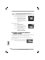
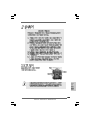
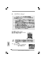
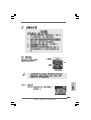
CPU InstallationCPU Installation
CPU InstallationCPU Installation
CPU Installation
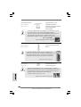
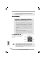
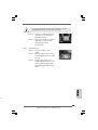
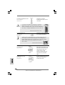
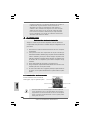
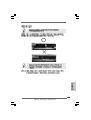
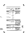
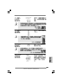
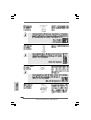
For the installation of Intel 1156-Pin CPU,
please follow the steps below.
Before you insert the 1156-Pin CPU into the socket, please check if
the CPU surface is unclean or if there is any bent pin on the socket.
Do not force to insert the CPU into the socket if above situation is
found. Otherwise, the CPU will be seriously damaged.
1156-Pin Socket Overview

1313
1313
13
ASRock P55 Deluxe3 Motherboard
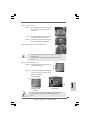
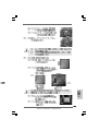
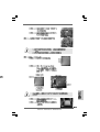
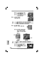
Step 1. Open the socket:
Step 1-1. Disengaging the lever by depressing
down and out on the hook to clear re-
tention tab.
Step 1-2. Rotate the load lever to fully open posi-
tion at approximately 135 degrees.
Step 1-3. Rotate the load plate to fully open posi-
tion at approximately 100 degrees.
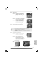
Step 2. Remove PnP Cap (Pick and Place Cap).
1. It is recommended to use the cap tab to handle and avoid kicking
off the PnP cap.
2. This cap must be placed if returning the motherboard for after
service.
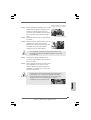
Step 3. Insert the 1156-Pin CPU:
Step 3-1. Hold the CPU by the edges where are
marked with black lines.
Step 3-2. Orient the CPU with IHS (Integrated Heat
Sink) up. Locate Pin1 and the two ori-
entation key notches.
For proper inserting, please ensure to match the two orientation
key notches of the CPU with the two alignment keys of the
socket.
black line
Pin1
alignment key
alignment key
Pin1
1156-Pin CPU
1156-Pin Socket
orientation key notch
orientation key notch
EnglishEnglish
EnglishEnglish
English

1414
1414
14
ASRock P55 Deluxe3 Motherboard
EnglishEnglish
EnglishEnglish
English
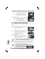
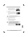
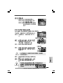
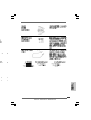
Step 3-3. Carefully place the CPU into the socket
by using a purely vertical motion.
Step 3-4. Verify that the CPU is within the socket
and properly mated to the orient keys.
Step 4. Close the socket:
Step 4-1. Rotate the load plate onto the IHS.
Step 4-2. While pressing down lightly on load
plate, engage the load lever.
Step 4-3. Secure load lever with load plate tab
under retention tab of load lever.
2.22.2
2.22.2
2.2
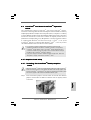
Installation of CPU Fan and HeatsinkInstallation of CPU Fan and Heatsink
Installation of CPU Fan and HeatsinkInstallation of CPU Fan and Heatsink
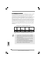
Installation of CPU Fan and Heatsink
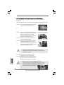
For proper installation, please kindly refer to the instruction manuals of your CPU fan and
heatsink.
Below is an example to illustrate the installation of the heatsink for 1156-Pin CPU.
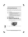
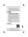
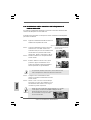
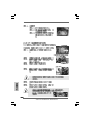
Step 1. Apply thermal interface material onto center of
IHS on the socket surface.
Step 2. Place the heatsink onto the socket. Ensure
fan cables are oriented on side closest to the
CPU fan connector on the motherboard
(CPU_FAN1, see page 2, No. 5).
Step 3. Align fasteners with the motherboard
throughholes.
Step 4. Rotate the fastener clockwise, then press down
on fastener caps with thumb to install and lock.
Repeat with remaining fasteners.
If you press down the fasteners without rotating them clockwise,
the heatsink cannot be secured on the motherboard.
Step 5. Connect fan header with the CPU fan connector on the motherboard.
Step 6. Secure excess cable with tie-wrap to ensure cable does not interfere with
fan operation or contact other components.
Please be noticed that this motherboard supports Combo Cooler
Option (C.C.O.), which provides the flexible option to adopt two
different CPU cooler types, Socket LGA
775 and LGA 1156. The white throughholes
are for Socket LGA 1156 CPU fan.

1515
1515
15
ASRock P55 Deluxe3 Motherboard
EnglishEnglish
EnglishEnglish
English
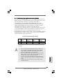
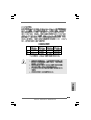
2.3 Installation of Memory Modules (DIMM)2.3 Installation of Memory Modules (DIMM)
2.3 Installation of Memory Modules (DIMM)2.3 Installation of Memory Modules (DIMM)
2.3 Installation of Memory Modules (DIMM)
This motherboard provides four 240-pin DDR3 (Double Data Rate 3) DIMM slots,
and supports Dual Channel Memory Technology. For dual channel configuration,
you always need to install identical (the same brand, speed, size and chip-
type) DDR3 DIMM pair in the slots of the same color. In other words, you have to
install identical DDR3 DIMM pair in Dual Channel (DDR3_A1 and DDR3_B1;
white slots; see p.2 No.7), so that Dual Channel Memory Technology can be
activated. This motherboard also allows you to install four DDR3 DIMMs for dual
channel configuration, and please install identical DDR3 DIMMs in all four slots.
You may refer to the Dual Channel Memory Configuration Table below.
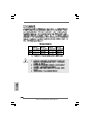
Dual Channel Memory Configurations
DDR3_A2 DDR3_A1 DDR3_B2 DDR3_B1
(Blue Slot) (White Slot) (Blue Slot) (White Slot)
(1) - Populated - Populated
(2)* Populated Populated Populated Populated
* For the configuration (2), please install identical DDR3 DIMMs in all four
slots.
1. If you want to install two memory modules, for optimal compatibility
and reliability, it is recommended to install them in the slots of the
same color. In other words, install them either in the set of white slots
(DDR3_A1 and DDR3_B1).
2. If only one memory module or three memory modules are installed
in the DDR3 DIMM slots on this motherboard, it is unable to activate
the Dual Channel Memory Technology.
3. It is not allowed to install a DDR or DDR2 memory module into
DDR3 slot;otherwise, this motherboard and DIMM may be damaged.
4. Please install the memory module into the white slot (DDR3_B1) for
the first priority.

1616
1616
16
ASRock P55 Deluxe3 Motherboard
EnglishEnglish
EnglishEnglish
English
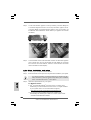
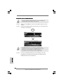
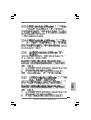
Installing a DIMMInstalling a DIMM
Installing a DIMMInstalling a DIMM
Installing a DIMM
Please make sure to disconnect power supply before adding or removing
DIMMs or the system components.
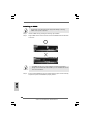
Step 1. Unlock a DIMM slot by pressing the retaining clips outward.
Step 2. Align a DIMM on the slot such that the notch on the DIMM matches the break
on the slot.
The DIMM only fits in one correct orientation. It will cause permanent
damage to the motherboard and the DIMM if you force the DIMM into the slot
at incorrect orientation.
Step 3. Firmly insert the DIMM into the slot until the retaining clips at both ends fully
snap back in place and the DIMM is properly seated.

1717
1717
17
ASRock P55 Deluxe3 Motherboard
EnglishEnglish
EnglishEnglish
English
2.4 Expansion Slots (PCI and PCI Express Slots)2.4 Expansion Slots (PCI and PCI Express Slots)
2.4 Expansion Slots (PCI and PCI Express Slots)2.4 Expansion Slots (PCI and PCI Express Slots)
2.4 Expansion Slots (PCI and PCI Express Slots)
There are 2 PCI slots and 4 PCI Express slots on this motherboard.
PCI slots: PCI slots are used to install expansion cards that have the 32-bit PCI
interface.
PCIE slots:
PCIE1 / PCIE3 (PCIE x1 slot; White) is used for PCI Express cards with
x1 lane width cards, such as Gigabit LAN card, SATA2 card, etc.
PCIE2 / PCIE4 (PCIE x16 slot; Blue) is used for PCI Express x16 lane
width graphics cards, or used to install PCI Express graphics cards to
support CrossFireX
TM
or SLI
TM
function.
1. In single VGA card mode, it is recommended to install a PCI Express
x16 graphics card on PCIE2 slot.
2. In CrossFireX
TM
mode or SLI
TM
mode, please install PCI Express x16
graphics cards on PCIE2 and PCIE4 slots. Therefore, both these two
slots will work at x8 bandwidth.
3. Please connect a chassis fan to motherboard chassis fan connector
(CHA_FAN1, CHA_FAN2 or CHA_FAN3) when using multiple
graphics cards for better thermal environment.
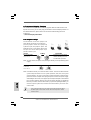
Installing an expansion cardInstalling an expansion card
Installing an expansion cardInstalling an expansion card
Installing an expansion card
Step 1. Before installing the expansion card, please make sure that the power
supply is switched off or the power cord is unplugged. Please read the
documentation of the expansion card and make necessary hardware
settings for the card before you start the installation.
Step 2. Remove the system unit cover (if your motherboard is already installed in
a chassis).
Step 3. Remove the bracket facing the slot that you intend to use. Keep the
screws for later use.
Step 4. Align the card connector with the slot and press firmly until the card is
completely seated on the slot.
Step 5. Fasten the card to the chassis with screws.
Step 6. Replace the system cover.

1818
1818
18
ASRock P55 Deluxe3 Motherboard
EnglishEnglish
EnglishEnglish
English
2.5 SLI2.5 SLI
2.5 SLI2.5 SLI
2.5 SLI
TMTM
TMTM
TM
and Quad SLI and Quad SLI
and Quad SLI and Quad SLI
and Quad SLI
TM TM
TM TM
TM
Operation GuideOperation Guide
Operation GuideOperation Guide
Operation Guide
This motherboard supports NVIDIA
®
SLI
TM
and Quad SLI
TM
(Scalable Link Interface)
technology that allows you to install up to two identical PCI Express x16 graphics
cards. Currently, NVIDIA
®
SLI
TM
technology supports Windows
®
XP / XP 64-bit /
Vista
TM
/ Vista
TM
64-bit / 7 / 7 64-bit OS. NVIDIA
®
Quad SLI
TM
technology support
Windows
®
Vista
TM
/ Vista
TM
64-bit / 7 / 7 64-bit OS only. Please follow the installation
procedures in this section.
Requirements
1. For SLI
TM
or Quad SLI
TM
technology, you should have two identical
SLI
TM
-ready graphics cards that are NVIDIA
®
certified.
2. Make sure that your graphics card driver supports NVIDIA
®
SLI
TM
technology. Download the driver from NVIDIA
®
website
(www.nvidia.com).
3. Make sure that your power supply unit (PSU) can provide at least the
minimum power required by your system. It is recommended to use
NVIDIA
®
certified PSU. Please refer to NVIDIA
®
website for details.
2.5.1 Graphics Card Setup2.5.1 Graphics Card Setup
2.5.1 Graphics Card Setup2.5.1 Graphics Card Setup
2.5.1 Graphics Card Setup
2.5.1.1 Installing T2.5.1.1 Installing T
2.5.1.1 Installing T2.5.1.1 Installing T
2.5.1.1 Installing T
wo SLIwo SLI
wo SLIwo SLI
wo SLI
TMTM
TMTM
TM
-R-R
-R-R
-R
eady Graphics Cardseady Graphics Cards
eady Graphics Cardseady Graphics Cards
eady Graphics Cards
Step 1. Install the identical SLI
TM
-ready graphics cards that are NVIDIA
®
certified
because different types of graphics cards will not work together properly.
(Even the GPU chips version shall be the same.) Insert one graphics card
into PCIE2 slot and the other graphics card to PCIE4 slot. Make sure that the
cards are properly seated on the slots.
Step2. If required, connect the auxiliary power source to the PCI Express graphics
cards.

1919
1919
19
ASRock P55 Deluxe3 Motherboard
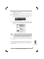
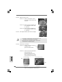
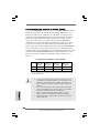
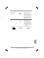
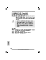
Step4. Connect a VGA cable or a DVI cable to the monitor connector or the DVI
connector of the graphics card that is inserted to PCIE2 slot.
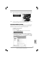
Step3. Align and insert ASRock SLI_Bridge_2S Card to the goldfingers on each
graphics card. Make sure ASRock SLI_Bridge_2S Card is firmly in place.
ASRock SLI_Bridge_2S Card
2.5.2 Driver Installation and Setup2.5.2 Driver Installation and Setup
2.5.2 Driver Installation and Setup2.5.2 Driver Installation and Setup
2.5.2 Driver Installation and Setup
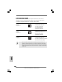
Install the graphics card drivers to your system. After that, you can enable the Multi-
Graphics Processing Unit (GPU) feature in the NVIDIA
®
nView system tray utility.
Please follow the below procedures to enable the multi-GPU feature.
For Windows
®
XP / XP 64-bit OS:
(For SLI
TM
mode only)
A. Double-click NVIDIA Settings icon on your Windows
®
taskbar.
B. From the pop-up menu, select Set SLI and PhysX configuration. In
Set PhysX GPU acceleration item, please select Enabled. In Select
an SLI configuration item, please select Enable SLI. And click Apply.
C. Reboot your system.
D. You can freely enjoy the benefit of SLI
TM
feature.
EnglishEnglish
EnglishEnglish
English

2020
2020
20
ASRock P55 Deluxe3 Motherboard
EnglishEnglish
EnglishEnglish
English
For Windows
®
7 / 7 64-bit / Vista
TM
/ Vista
TM
64-bit OS:
(For SLI
TM
and Quad SLI
TM
mode)
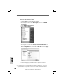
A. Click the Start icon on your Windows taskbar.
B. From the pop-up menu, select All Programs, and then click NVIDIA
Corporation.
C. Select NVIDIA Control Panel tab.
D. Select Control Panel tab.
E. From the pop-up menu, select Set SLI and PhysX configuration. In
Set PhysX GPU acceleration item, please select Enabled. In Select
an SLI configuration item, please select Enable SLI. And click Apply.
F. Reboot your system.
G. You can freely enjoy the benefit of SLI
TM
or Quad SLI
TM
feature.
* SLI
TM
appearing here is a registered trademark of NVIDIA
®
Technologies Inc., and is used
only for identification or explanation and to the owners’ benefit, without intent to infringe.
La page est en cours de chargement...
La page est en cours de chargement...
La page est en cours de chargement...
La page est en cours de chargement...
La page est en cours de chargement...
La page est en cours de chargement...
La page est en cours de chargement...
La page est en cours de chargement...
La page est en cours de chargement...
La page est en cours de chargement...
La page est en cours de chargement...
La page est en cours de chargement...
La page est en cours de chargement...
La page est en cours de chargement...
La page est en cours de chargement...
La page est en cours de chargement...
La page est en cours de chargement...
La page est en cours de chargement...
La page est en cours de chargement...
La page est en cours de chargement...
La page est en cours de chargement...
La page est en cours de chargement...
La page est en cours de chargement...
La page est en cours de chargement...
La page est en cours de chargement...
La page est en cours de chargement...
La page est en cours de chargement...
La page est en cours de chargement...
La page est en cours de chargement...
La page est en cours de chargement...
La page est en cours de chargement...
La page est en cours de chargement...
La page est en cours de chargement...
La page est en cours de chargement...
La page est en cours de chargement...
La page est en cours de chargement...
La page est en cours de chargement...
La page est en cours de chargement...
La page est en cours de chargement...
La page est en cours de chargement...
La page est en cours de chargement...
La page est en cours de chargement...
La page est en cours de chargement...
La page est en cours de chargement...
La page est en cours de chargement...
La page est en cours de chargement...
La page est en cours de chargement...
La page est en cours de chargement...
La page est en cours de chargement...
La page est en cours de chargement...
La page est en cours de chargement...
La page est en cours de chargement...
La page est en cours de chargement...
La page est en cours de chargement...
La page est en cours de chargement...
La page est en cours de chargement...
La page est en cours de chargement...
La page est en cours de chargement...
La page est en cours de chargement...
La page est en cours de chargement...
La page est en cours de chargement...
La page est en cours de chargement...
La page est en cours de chargement...
La page est en cours de chargement...
La page est en cours de chargement...
La page est en cours de chargement...
La page est en cours de chargement...
La page est en cours de chargement...
La page est en cours de chargement...
La page est en cours de chargement...
La page est en cours de chargement...
La page est en cours de chargement...
La page est en cours de chargement...
La page est en cours de chargement...
La page est en cours de chargement...
La page est en cours de chargement...
La page est en cours de chargement...
La page est en cours de chargement...
La page est en cours de chargement...
La page est en cours de chargement...
La page est en cours de chargement...
La page est en cours de chargement...
La page est en cours de chargement...
La page est en cours de chargement...
La page est en cours de chargement...
La page est en cours de chargement...
La page est en cours de chargement...
La page est en cours de chargement...
La page est en cours de chargement...
La page est en cours de chargement...
La page est en cours de chargement...
La page est en cours de chargement...
La page est en cours de chargement...
La page est en cours de chargement...
La page est en cours de chargement...
La page est en cours de chargement...
La page est en cours de chargement...
La page est en cours de chargement...
La page est en cours de chargement...
La page est en cours de chargement...
La page est en cours de chargement...
La page est en cours de chargement...
La page est en cours de chargement...
La page est en cours de chargement...
La page est en cours de chargement...
La page est en cours de chargement...
La page est en cours de chargement...
La page est en cours de chargement...
La page est en cours de chargement...
La page est en cours de chargement...
La page est en cours de chargement...
La page est en cours de chargement...
La page est en cours de chargement...
La page est en cours de chargement...
La page est en cours de chargement...
La page est en cours de chargement...
La page est en cours de chargement...
La page est en cours de chargement...
La page est en cours de chargement...
La page est en cours de chargement...
La page est en cours de chargement...
La page est en cours de chargement...
La page est en cours de chargement...
La page est en cours de chargement...
La page est en cours de chargement...
La page est en cours de chargement...
La page est en cours de chargement...
La page est en cours de chargement...
La page est en cours de chargement...
La page est en cours de chargement...
La page est en cours de chargement...
La page est en cours de chargement...
La page est en cours de chargement...
La page est en cours de chargement...
La page est en cours de chargement...
La page est en cours de chargement...
La page est en cours de chargement...
La page est en cours de chargement...
La page est en cours de chargement...
La page est en cours de chargement...
La page est en cours de chargement...
La page est en cours de chargement...
La page est en cours de chargement...
La page est en cours de chargement...
La page est en cours de chargement...
La page est en cours de chargement...
La page est en cours de chargement...
La page est en cours de chargement...
La page est en cours de chargement...
La page est en cours de chargement...
La page est en cours de chargement...
La page est en cours de chargement...
La page est en cours de chargement...
La page est en cours de chargement...
La page est en cours de chargement...
La page est en cours de chargement...
La page est en cours de chargement...
La page est en cours de chargement...
La page est en cours de chargement...
La page est en cours de chargement...
La page est en cours de chargement...
La page est en cours de chargement...
La page est en cours de chargement...
La page est en cours de chargement...
La page est en cours de chargement...
La page est en cours de chargement...
La page est en cours de chargement...
La page est en cours de chargement...
La page est en cours de chargement...
La page est en cours de chargement...
La page est en cours de chargement...
La page est en cours de chargement...
La page est en cours de chargement...
La page est en cours de chargement...
La page est en cours de chargement...
La page est en cours de chargement...
La page est en cours de chargement...
La page est en cours de chargement...
La page est en cours de chargement...
La page est en cours de chargement...
La page est en cours de chargement...
La page est en cours de chargement...
La page est en cours de chargement...
La page est en cours de chargement...
La page est en cours de chargement...
La page est en cours de chargement...
La page est en cours de chargement...
La page est en cours de chargement...
La page est en cours de chargement...
La page est en cours de chargement...
La page est en cours de chargement...
La page est en cours de chargement...
La page est en cours de chargement...
La page est en cours de chargement...
La page est en cours de chargement...
La page est en cours de chargement...
La page est en cours de chargement...
La page est en cours de chargement...
La page est en cours de chargement...
La page est en cours de chargement...
La page est en cours de chargement...
La page est en cours de chargement...
La page est en cours de chargement...
La page est en cours de chargement...
La page est en cours de chargement...
La page est en cours de chargement...
-
 1
1
-
 2
2
-
 3
3
-
 4
4
-
 5
5
-
 6
6
-
 7
7
-
 8
8
-
 9
9
-
 10
10
-
 11
11
-
 12
12
-
 13
13
-
 14
14
-
 15
15
-
 16
16
-
 17
17
-
 18
18
-
 19
19
-
 20
20
-
 21
21
-
 22
22
-
 23
23
-
 24
24
-
 25
25
-
 26
26
-
 27
27
-
 28
28
-
 29
29
-
 30
30
-
 31
31
-
 32
32
-
 33
33
-
 34
34
-
 35
35
-
 36
36
-
 37
37
-
 38
38
-
 39
39
-
 40
40
-
 41
41
-
 42
42
-
 43
43
-
 44
44
-
 45
45
-
 46
46
-
 47
47
-
 48
48
-
 49
49
-
 50
50
-
 51
51
-
 52
52
-
 53
53
-
 54
54
-
 55
55
-
 56
56
-
 57
57
-
 58
58
-
 59
59
-
 60
60
-
 61
61
-
 62
62
-
 63
63
-
 64
64
-
 65
65
-
 66
66
-
 67
67
-
 68
68
-
 69
69
-
 70
70
-
 71
71
-
 72
72
-
 73
73
-
 74
74
-
 75
75
-
 76
76
-
 77
77
-
 78
78
-
 79
79
-
 80
80
-
 81
81
-
 82
82
-
 83
83
-
 84
84
-
 85
85
-
 86
86
-
 87
87
-
 88
88
-
 89
89
-
 90
90
-
 91
91
-
 92
92
-
 93
93
-
 94
94
-
 95
95
-
 96
96
-
 97
97
-
 98
98
-
 99
99
-
 100
100
-
 101
101
-
 102
102
-
 103
103
-
 104
104
-
 105
105
-
 106
106
-
 107
107
-
 108
108
-
 109
109
-
 110
110
-
 111
111
-
 112
112
-
 113
113
-
 114
114
-
 115
115
-
 116
116
-
 117
117
-
 118
118
-
 119
119
-
 120
120
-
 121
121
-
 122
122
-
 123
123
-
 124
124
-
 125
125
-
 126
126
-
 127
127
-
 128
128
-
 129
129
-
 130
130
-
 131
131
-
 132
132
-
 133
133
-
 134
134
-
 135
135
-
 136
136
-
 137
137
-
 138
138
-
 139
139
-
 140
140
-
 141
141
-
 142
142
-
 143
143
-
 144
144
-
 145
145
-
 146
146
-
 147
147
-
 148
148
-
 149
149
-
 150
150
-
 151
151
-
 152
152
-
 153
153
-
 154
154
-
 155
155
-
 156
156
-
 157
157
-
 158
158
-
 159
159
-
 160
160
-
 161
161
-
 162
162
-
 163
163
-
 164
164
-
 165
165
-
 166
166
-
 167
167
-
 168
168
-
 169
169
-
 170
170
-
 171
171
-
 172
172
-
 173
173
-
 174
174
-
 175
175
-
 176
176
-
 177
177
-
 178
178
-
 179
179
-
 180
180
-
 181
181
-
 182
182
-
 183
183
-
 184
184
-
 185
185
-
 186
186
-
 187
187
-
 188
188
-
 189
189
-
 190
190
-
 191
191
-
 192
192
-
 193
193
-
 194
194
-
 195
195
-
 196
196
-
 197
197
-
 198
198
-
 199
199
-
 200
200
-
 201
201
-
 202
202
-
 203
203
-
 204
204
-
 205
205
-
 206
206
-
 207
207
-
 208
208
-
 209
209
-
 210
210
-
 211
211
-
 212
212
-
 213
213
-
 214
214
-
 215
215
-
 216
216
-
 217
217
-
 218
218
-
 219
219
-
 220
220
-
 221
221
-
 222
222
-
 223
223
-
 224
224
-
 225
225
-
 226
226


ASROCK P55 DELUXE3 Le manuel du propriétaire
- Catégorie
- Cartes mères
- Taper
- Le manuel du propriétaire
- Ce manuel convient également à
dans d''autres langues
- italiano: ASROCK P55 DELUXE3 Manuale del proprietario
- English: ASROCK P55 DELUXE3 Owner's manual
- español: ASROCK P55 DELUXE3 El manual del propietario
- Deutsch: ASROCK P55 DELUXE3 Bedienungsanleitung
Documents connexes
-
ASROCK A55iCafe Guide de démarrage rapide
-
ASROCK P55 Deluxe Le manuel du propriétaire
-
ASROCK P55 PRO Le manuel du propriétaire
-
ASROCK P55DE PRO Le manuel du propriétaire
-
ASROCK ALIVENF5SLI-1394 Le manuel du propriétaire
-
ASROCK A75M Guide de démarrage rapide
-
ASROCK H55M Manuel utilisateur
-
-
ASROCK H55 PRO Le manuel du propriétaire
-
ASROCK X58 DELUXE Le manuel du propriétaire
