Bertazzoni REF30BMBIXLT 15.5 cu. ft. Built-in Bottom Freezer Refrigerator Guide d'installation
- Taper
- Guide d'installation

REF30BMBIXLT
REF30BMBIXRT
REF30BMBIPLT
REF30BMBIPRT
REF36BMBIXLT
REF36BMBIXRT
REF36BMBIPLT
REF36BMBIPRT
EN
FR
ES
Refrigerator Installation Guide
Réfrigérateur Guide d’installation
Frigorífico Guía de instalación

www.bertazzoni.com www.universal.bertazzoni.com
IMPORTANT
When not otherwise pecified:
Dimension parentheses are in inches: mm (in)
Weights in parentheses are in pounds: kg (lb)
Temperatures in parentheses are in Fahrenheit degrees: °C (°F)

EN
www.universal.bertazzoni.com
3
1
1.1
1.2
IMPORTANT INSTRUCTIONS
Important safety instructions......................................................................................................................................
Children safety................................................................................................................................................................
4
4
4
2
2.1
2.2
2.3
TECHNICAL REQUIREMENTS
Appliance features and installation requirements................................................................................................
Installation niche features: Integrated Series....................................................................................................
Installation niche requirements: Stainless Integrated Series......................................................................
5
5
6
7
3
3.1
3.2
3.3
PREPARING TO INSTALL
Transport to installation site and unpacking..........................................................................................................
Electrical and Water connection..................................................................................................................................
Levelling............................................................................................................................................................................
8
8
8
9
4
4.1
4.2
4.3
4.4
PANELS MOUNTING
Door and Bottom-Drawer overlay panels layout................................................................................................
Overlay panels mounting brackets layout
Panels dimensions..........................................................................................................................................................
Mounting panels to the door and the drawer of Integrated units.....................................................................
10
10
11
11
13
5
5.1
5.2
INSTALLATION
Built-in installation of single appliance.................................................................................................................
Built-in installation of two or more appliances..................................................................................................
15
15
16
6
6.1
6.2
6.3
6.4
COMPLETING THE INSTALLATION
Anti-tipping safety assembly.......................................................................................................................................
Ventilation.........................................................................................................................................................................
Post installation control .............................................................................................................................................
Start up...............................................................................................................................................................................
18
18
19
20
20
INDEX
www.bertazzoni.com

www.universal.bertazzoni.com
4
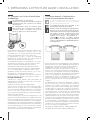
1.1 Important safety instructions
Symbols used in the Guide:
Note
Tips for the correct use of
the appliance
Important
Directions to avoid appliance
damage
Attention
Directions to prevent
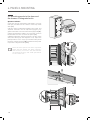
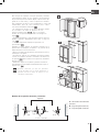
1.2 Children safety
DANGER: Risk of child entrap-
ment. Before you throw away your
old refrigerator or freezer:
• Take off the doors
• Leave the shelves in place so
that children may not easily
climb inside.
Attention!
This appliance must be
transported in an upright
position. If this was not
the case you should leave
it upright for 24 hours
prior to switch it on.
Take maximum care
during handling to avoid
harm to persons and
property.
Secure the top of the
appliance to the wall
with the two brackets
provided with the
appliance.
1. IMPORTANT INSTRUCTIONS
24 h
!! ATTENZIONE !! - !! ATTENTION !!
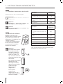
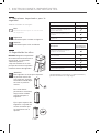
CONTENUTO IMBALLO - PACKING CONTENTS
CONTENUTO KIT ACCESSORI - OWNER KIT CONTENTS
Descrizione - Description StandPlus/
X-pro Integrated Classic
Apparecchiatura
Appliance
Staffe, squadrette, viti, chiave per fissare pannelli esterni
Fasteners, brackets, screws, wrench for mounting outer panels
Profilati in alluminio per chiusura spazi tra apparecchiature e mobili
Alluminium trims to ll gap between appliance and cabinets
Kit accessori (all’interno dell’apparecchiatura)
Owner’s Kit (inside the appliance)
Descrizione - Description
Modelli con Ice
Maker - Models
with Ice Maker
Modelli senza Ice
Maker - Models
without Ice Maker
Tubo di collegamento alla rete idraulica (solo modelli con Ice Maker)
Water ll hose (only models with Ice Maker)
Filtro acqua (solo modelli con Ice Maker)
Water lter (only models with Ice Maker)
Piedini livellatori
Leveling feet
Squadrette antiribaltamento, tasselli e viti per il fissaggio delle squadrette antiribaltamento
Anti-tipping brackets, xing plugs and screws
Kit per la pulizia dell’apparecchiatura
Appliance cleaning kit
Manuale d’uso, guida di installazione, certificato di garanzia
User Manual, Installation Guide, Guarantee Certicate
Leggete con attenzione e conservate con cura la Guida Installazione e il Manuale d’uso forniti con l’apparecchiatura.
Read the User Manual and the Guide attentively and keep it in a safe place.
13-04-12 / B09010102 ML
24 h
!! ATTENZIONE !! - !! ATTENTION !!
CONTENUTO IMBALLO - PACKING CONTENTS
CONTENUTO KIT ACCESSORI - OWNER KIT CONTENTS
Descrizione - Description StandPlus/
X-pro Integrated Classic
Apparecchiatura
Appliance
Staffe, squadrette, viti, chiave per fissare pannelli esterni
Fasteners, brackets, screws, wrench for mounting outer panels
Profilati in alluminio per chiusura spazi tra apparecchiature e mobili
Alluminium trims to ll gap between appliance and cabinets
Kit accessori (all’interno dell’apparecchiatura)
Owner’s Kit (inside the appliance)
Descrizione - Description
Modelli con Ice
Maker - Models
with Ice Maker
Modelli senza Ice
Maker - Models
without Ice Maker
Tubo di collegamento alla rete idraulica (solo modelli con Ice Maker)
Water ll hose (only models with Ice Maker)
Filtro acqua (solo modelli con Ice Maker)
Water lter (only models with Ice Maker)
Piedini livellatori
Leveling feet
Squadrette antiribaltamento, tasselli e viti per il fissaggio delle squadrette antiribaltamento
Anti-tipping brackets, xing plugs and screws
Kit per la pulizia dell’apparecchiatura
Appliance cleaning kit
Manuale d’uso, guida di installazione, certificato di garanzia
User Manual, Installation Guide, Guarantee Certicate
Leggete con attenzione e conservate con cura la Guida Installazione e il Manuale d’uso forniti con l’apparecchiatura.
Read the User Manual and the Guide attentively and keep it in a safe place.
13-04-12 / B09010102 ML
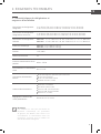
Description Integrated
Appliance
Fasteners, brackets, screws, wrench
for mounting outer panels
Alluminium trims to fill gap between
appliance and cabinets
Owner’s Kit (inside the appliance)
Read the User Manual and the Guide attentively and keep it in a
safe place.
Description Maker - Models
with Ice Maker
Water fill hose (only models with Ice
Maker)
Water filter (only models with Ice
Maker)
Leveling feet
Anti-tipping brackets, fixing plugs and
screws
Appliance cleaning kit
User Manual, Installation Guide,
Guarantee Certificate

EN
www.universal.bertazzoni.com
5
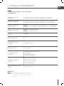
Appliance dimensions
Integrated
w: 29 15/16" (761 mm) / h: 83 1/2" (2120 mm) / d: 24” (610 mm)
w: 35 15/16" (913 mm) / h: 83 1/2" (2120 mm) / d: 24” (610 mm)
Appliance dimensions
Stainless Integrated w: 29 15/16" (761 mm) / h: 83 1/2" (2120 mm) / d: 24 3/16" (615 mm)
w: 35 15/16" (913 mm) / h: 83 1/2" (2120 mm) / d: 24 3/16" (615 mm)
Appliance dimensions
with packaging
75 Series w: 31 1/2” (800 mm) / h: 89” (2260 mm) / d: 31 1/2” (800 mm)
90 Series w: 37 3/8” (950 mm) / h: 89” (2260 mm) / d: 31 1/2” (800 mm)
Weight with packaging 75 Series up to 606 lb (275 kg)
90 Series up to 650 lb (295 kg)
Voltage 115V, 60Hz
Power supply cable 3A
Potable water supply
pressure From 8 PSI to 75 PSI
Water connection 1/4” attachment
Provided installation
accessories
Customized panels mounting Kit
Anti-tipping Kit
Lateral connecting kit
1/8” (4 mm) allen wrench
Additional equipment
necessary
Phillips head screwdriver
wood and percussion drill
1/8” (2.5 mm) bit for wood
3/8” (8 mm) bit for walls
3/4” (17 mm) wrench
Adjusting height of the rear
rollers 1/2” (13 mm) socket
2.1 Appliance features and installation
requirements
2. TECHNICAL REQUIREMENTS
Note
Not all models come with an automatic ice
maker. Verify if your model is equipped with
an ice maker to determine if you require
water supply.

www.universal.bertazzoni.com
6
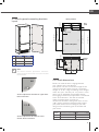
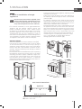
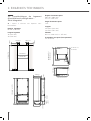
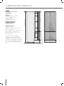
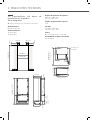
2.2 Installation niche features:
Integrated Series
A - area to be left clear for the anti-tipping brackets
Niche Height
83 7/8" (2130 mm)
Niche Width
36" (914 mm)
30" (762 mm)
2. TECHNICAL REQUIREMENTS
Door Swing Clearance
58 7/16" (1484 mm)
52 1/2" (1333 mm)
Door Opening Angle
105°
Width
35 15/16" (913 mm)
29 15/16" (761 mm)
Height
83 1/2" (2120 mm) + 1" (25 mm)
Depth with door (without panel)
24” (610 mm)
Français
610 (24”)
560 (22 1/16")
474
(18 ⅝”)
231 (9
⅛”
) +
25 (1”)
248 (9
¾”
)
+ 25 (1”)
20 (¾”) 15 (⅝”)
721 (28 ⅜”) +25 (1”)
A A
E W E W
140 (5 ½”) 140 (5 ½”)
100 (4”)
100 (4”)
2130 (83 7/8”)
90: 914 (36”)
75: 762 (30”)
500 (19 )
¾”
560 (22”)
610 (24”)
90: 899 (35 3/8”)
75: 749 (29 1/2”)
10 (⅜”)
105°
992 (39”)
90: 1470 (57 7/8”)
75: 1320 (52”)
90: 160 (6 1/4”)
75: 125 (5”)
610 (24”)
)”22(065
1293 (50 ⅞” )
474
(18 ⅝”)
231(9
⅛”
)+
25 (1”)
248(9
¾”
)
+ 25 (1”)
20 (¾”) 15 (⅝”)
721 (28 ⅜”) +25 (1”)
2050 (80 ¾”) +25 (1”)
0T
A A
E W E W
140 (5 ½”) 140 (5 ½”)
100 (4”)
100 (4”)
min 2064 (81 ¼”)
90: 900 (35 ½”)
75: 750 (29 ⅝”)
500 (19 )
¾”
560 (22 1/16”)
610 (24”)
90: 913 (35 15/16”)
75: 761 (29 15/16”)
10 (⅜”)
105°
992 (39”)
90: 160 (6 1/4”)
75: 125 (5”)
90: 1484 (58 7/16”)
75: 1333 (52 1/2”)
2120 (83 ½") + 25 (1")
1299 (51 1/8")

EN
www.universal.bertazzoni.com
7
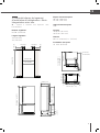
2.3 Installation niche requirements:
Stainless Integrated Series
A - area to be left clear for the anti-tipping brackets
Niche Height
83 7/8" (2130 mm)
Niche Width
36" (914 mm)
30" (762 mm)
Door Swing Clearance
58 3/8" (1482 mm)
52 3/8" (1331 mm)
Door Opening Angle
105°
Width
35 15/16" (913 mm)
29 15/16" (761 mm)
Height
83 1/2" (2120 mm) + 1" (25 mm)
Depth with door (with panel)
24 3/16" (615 mm)
A A
E W E W
140 (5 ½”) 140 (5 ½”)
100 (4”)
100 (4”)
90: 914 (36”)
75: 762 (30”)
615 (24 3/16”)
560 (22 1/16")
693 (27 ¼”)
587 (23 ⅛”)
146 (5
¾”)
+ 25 (1”)
9 ( ⅜”)
732 (28 ⅞”)+25 (1”)
105°
90: 1470 (57
⅞”
)
75: 1320 (52”)
90: 230 (9”)
75: 195 (7 ¾”)
90: 899 (35 ⅜”)
75: 749 (29 ½”)
10 (⅜”)
75 (3”)
58 (2 ¼”)
1016 (40”)
635 (25”)
560 (22”)
A A
E W E W
140 (5 ½”) 140 (5 ½”)
100 (4”)
100 (4”)
min 2064 (81 ¼”)
90: 900 (35 ½”)
75: 750 (29 ⅝”)
635 (25”)
560 (22”)
0T
693 (27 ¼”)
2050 (80 ¾”) +25 (1”)
1308 (51 ½”)587 (23 ⅛”)
146 (5 ¾”)
+ 25(1”)
9 ( ⅜”)
732 (28 ⅞”)+25 (1”)
105°
90: 230 (9”)
75: 195 (7 ¾”)
10 (⅜”)
75 (3”)
58 (2 ¼”
)
1016 (40”)
615 (24 3/16”)
560 (22 1/16”)
90: 1482 (58 ⅜”)
75: 1331 (52 ⅜”)
2120 (83 ½") + 25 (1")
2130 (83 7/8")
1378 (54 1/4")
90: 913 (35 15/16”)
75: 761 (29 15/16”)

www.universal.bertazzoni.com
8
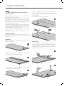
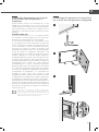
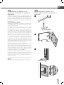
3.1 Transport to installation site and
unpacking
The appliance is very heavy.
Take maximum care during handling to
avoid injury.
The appliance should always be transpor-
ted in an erect position. Avoid at all costs
leaning it on its front side.
Since this is a large and heavy appliance, before tran-
sporting the appliance, check the access to the loca-
tion where it will be installed (door size, manoeuvring
space in stairwells, etc.).
The appliance is attached to the base of the packa-
ging (pallet) through four bolts which can be removed
using a 3/4” (19 mm) wrench.
It is recommended to use a manual transporting de-
vice to move the appliance to the installation site, and
only at this point to remove the base of the packaging.
The appliance should always be transported in an
erect position. If this is not possible, transport the ap-
pliance laying on its rear side.
Once at the installation site, the appliance, which is
equipped with four wheels, can be taken off the pallet
and positioned in the installation area.
Operate as follows:
>Take off the four bolts [ 1 ] securing the appliance
to the pallet by means of a 3/4” (19 mm) wrench or
socket.
>Remove the fixing brackets [ 3 ] and [ 4 ].
>To remove the front fixing bracket [ 3 ], unscrew for
one or two turns the rear wheel adjusting bolt [ 2 ] by
means of a 1/2” (13 mm) socket, do not overtighten
the nut as it could damage the leveling feet adjusting
system.
> From the back of the unit and by means of a suitable,
high duty hand trolley, take off the appliance and place
it on the floor. Be mindful of any debris on the floor
which could get caught under the rollers and poten-
tially damage the flooring when moving the appliance.
Be very careful to avoid any damage to floors. Delicate
floors should be protected with plywood, hard cardbo-
ard or similar material panels.
3. PREPARING THE INSTALLATION
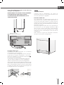
3.2 Electrical and water connection
The Built-in filter cannot make it safe to
drink any water which is not suitable for
human consumption.
The appliance should be connected only to
a drinkable water supply system.
Do not use extension cords or adapters.
Once the appliance is fully installed, con-
nected to the water supply (if applicable) and
operational, in the event that the water supply
must be turned off, (touch the button on
control panel to switch it off) before the main
water is shut off to prevent the appliance
from entering a ‘NO WATER IN’ alarm state.
The appliances are delivered from the factory for ope-
ration at 115V, 60Hz.
Do not connect the refrigerator to any GFCI receptacle.
They are provided with a suitable supply cable
and plug to be connected to an appropriate 15A
socket provided with an effective grounding. A
circuit breaker should also be installed and should
be easily accessible so that it can be easily switched
off before performing any installation or maintenance.
To connect to the water supply system (for appliances
equipped with ice makers) a 1/4” waterline with ac-
cessible shut-off valve must be supplied.
The appliance is provided with a water adapter elbow
which is suitable for high water pressure and com-
plies the Food Regulations. The water filter cartridge,
which is provided with the appliance, should be instal-
led according to the accompanying instructions. Use
only the new adapter which is supplied with the ap-
pliance. The solenoid connection on the appliance
is 1/4” diameter but is metric threaded. A standard
garden hose threaded connector such as a braided
stainless hose found at typical hardware stores will
strip or damage the solenoid threads. Use only the
supplied 1/4” quick connect elbow adapter for con-
necting a 1/4” copper or polyethylene source water
line to the appliance.
Electrical cord length: 98 3/8” (2500 mm)
Water connection line length: 98 3/8” (2500 mm)
1
4
1
2
3

EN
www.universal.bertazzoni.com
9
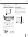
Do not use extension cords and/or multiple adapters
for the power supply connection.
ELECTRICAL AND WATER SUPPLY BEHIND THE UNIT
INTEGRATED SERIES
Operate as follows:
>Unwind the electric cable and connect it directly to
the wall socket.
>Make sure the appliance is in the Stand-by condition
and that all lights are off; should it be not so press the
Unit button to switch it off.
>Push the 1/4” source waterline fully into the elbow
connector thenthread the elbow adapter to the sole-
noid at the back of the appliance.
Firmly tighten with fingers - a tool /wrench should not
be needed to make a proper seal.
Turn on the water and ensure all connections are not
leaking prior to pushing the unit into the niche.
Back of appliance
Water connection
Electrical connection
E
W
E
W
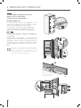
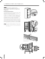
3.3 Levelling
Adjust the appliance level by means of the front level-
ling feetand the rear adjustable wheels.
Operate as follows:
>The grille should ship taped to the back of the ap-
pliance. If by chanceit is already in place, remove the
grille (it is kept in position by magnets), adjust the
height of the levelling feet [ 1 ] by means of a
3/4” (17 mm) wrench.
>Then adjust the height of the rear wheels by turning
the front adjusting bolts [ 2 ] clockwise or counter-
clockwise as it may be required. (Do not use power
drivers with high torque settings for this step as it
could damage the levelling mechanism)
>Mount the lower ventilation grille only after the unit
is finally levelled in the niche.
1
2
1
2

www.universal.bertazzoni.com
10
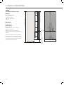
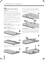
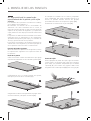
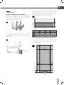
4.1 Door and Bottom-Drawer overlay
panels layout
The dimensions of the panels are indicated in the
table and drawings on pages 13.
Nevertheless, according to the requirements for
aligning with other kitchen structures, the door pa-
nel can be higher than the upper edge of the re-
frigerator door, and the drawer panel can be lower
than the edge of the drawer.
The panels must be mounted using special braces
which attach to adjustable devices provided on the
door and drawer and with brackets that anchor and
adjust the panel’s vertical direction.
Braces, brackets and fixing screws are provided
with the appliance and must be applied to the panel
as indicated.
Operate as follows:
To prepare the panels to be mounted on the ap-
pliance, follow these steps, working on the back of
the panel.
Door panel
>Draw a reference center line, dividing the panel
width in half [ 1 ].
>Starting from the bottom edge of the panel, mark
the positioning of the brackets [ 2 ].
>Following the corresponding table, mark the out-
side and then the inside hole[ 3 ].
4. PANELS MOUNTING
>Position the brackets on each set of marks to
make sure they are aligned [ 4 ], you may wish to
drill pilot holes (pay close attention to the panel’s
thickness) [ 5 ]
>Screw the brackets in place [ 6 ].
Drawer panel
>When preparing the Drawer Panel, follow the
same instructions as per the door panel, but make
sure measurements are taken starting from the top
edge[ 7 ]. The support bracket faces the opposite
way [ 8 ] (note imgs 4 and 8).
8
7
65
4
3
2
1

EN
www.universal.bertazzoni.com
11
4.2 Overlay panels mounting brackets
layout
90 SERIES 75 SERIES
A35 3/4” (908) 29 3/4” (756)
B13 1/2” (343)
C14” (354.5) 11” (279.5)
A
B B
A
B B
C C
13 (½”)
34 (1 )
6,5 (¼”) 6,5 (¼”)
34 (1 )
1273 (50 )
1163(45¾”)
660 (26”)
157 (6 ¼”)
min 1320 (52”)max 635(25”)
507.5 (20”)
382 (15)
100 (4”)
Français
4.3 Panels dimensions
Panels can have thickness ranging between
3/4” (18 mm) and 1 1/8" (28 mm).
Door panels can have a maximum weight 51 lbs
(23 kg) and drawer panels may be a maximum
weight of 25 lbs (11kg). Exceeding these weights
could void your warranty for any service issues
which can be attributed to overweight panels.
The hinging mechanism on appliances is considered
to be `Zero-clearance`. The door and drawer
widths specified below assume the
minimum niche width is being used and a 3.2 mm
(1/8”) reveal is desired around the panels. Adjust
your panel dimensions accordingly to your own
design criteria considering your niche width and
your reveal.
Note
All lateral bracket placement measure-
ments go from the center line to the outside
bracket hole.
Vertical adjustment bracket for upper door.
Note orientation.
Vertical adjustment bracket for lower
drawer. Note orientation.
A
B B
A
B B
C C
13 (½”)
34 (1 )
6,5 (¼”) 6,5 (¼”)
34 (1 )
1273 (50 )
1163(45¾”)
660 (26”)
157 (6 ¼”)
min 1320 (52”)max 635(25”)
507.5 (20”)
382 (15)
100 (4”)
Français
A
B B
A
B B
C C
13 (½”)
34 (1 )
6,5 (¼”) 6,5 (¼”)
34 (1 )
1273 (50 )
1163(45¾”)
660 (26”)
157 (6 ¼”)
min 1320 (52”)max 635(25”)
507.5 (20”)
382 (15)
100 (4”)
Français
A
A
B B
C C
100 (3 7/8”)
Français
Holes positions
Back of the panel Drawer
panel
SERIES DOOR/DRAWER WIDTH NICHE WIDTH
90 35 3/4” (908)
75 29 3/4” (756) 30" (762)
16 1/2” (418)
Door
panel
BB
34 (1 3/8”)
13 (1/2")
1273 (50 1/8”)
1233 (48 1/2")
730 (28 3/4")
227 (8 7/8")
1390 (54 3/4”)
Back of the panel
36" (914)
min 547 (21 1/2")
max 654 (25 3/4")
508 (20”)
382 (15")
34 (1 3/8”)
13 (1/2")

www.universal.bertazzoni.com
12
4. PANELS MOUNTING
115 (4 ½”)
(7 )
135
(5 )
1075 (42 )
A
4.3 Panels dimensions
Example:
83 7/8" niche height
36" niche width
4” toe kick height
1/8” gap desired all
around
Door panel:
Width: 35 3/4"
Height: 54 3/4"
Drawer panel:
Width: 35 3/4"
Height: 83 7/8" - 1/8” - 54 3/4" -
1/8" - 4" = 24 7/8"
With a 6” toe kick, the bottom
drawer panel height would become
22 7/8".
The formula above allows to obtain
the freezer drawer panel flush with
the toe kick. It is possible to extend
the freezer drawer panel by 13/16"
to cover the toe kick more.
2120 (83 1/2") + 25 (1")
1390 (54 3/4")
3,2 (1/8")
min 547 (21 1/2")
min 80 (3 1/8")
max 654 (25 3/4")
max 187 (7 3/8")

EN
www.universal.bertazzoni.com
13
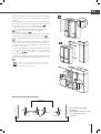
4.4 Mounting panels to the door and
the drawer of Integrated units
Install 1 hanger bolt about 3 threads deep and 1 depth
set screw flush to foam gasket in each mounting ca-
vity. Once all brackets and small brackets have been
applied to the panels, you can begin installing the bot-
tom drawer.
Operate as follows:
>Partially install the adjustment bolt with washer
into the two holes in the bottom of the drawer [ 1 ].
>Ensure the L-brackets align with the adjustment
bolts on the bottom, place panel against the drawer
face with the hanger brackets above the hanger
bolts and allow the panel to drop down. Ensure all
the hanger brackets engage the hanger bolts [ 2 ].
>It is now possible to align panels to adjacent cabi-
nets in height using the lower alignment brackets,
[ 3 ] tightening or untighteningthe bolts into position
as needed. With the hanger bolts slighty tightened,
move the panel sideways to align it to the other pa-
nels on the unit or other adjacent structures.
Tapping the panel with a rubber mallet is a good
way to make small adjustments to the X-alignment
of the panel.
>Depth alignment: working from the inside of the
drawer, after lifting up the magnetic seal, adjust
the panel position so it is closer to or further away
from the door using the holes [ 4 ] and then secure
the panel using the holes [ 5 ].
Turning in the direction of the thick arrow pulls the
panel closer to the door/drawer face, turning in the
direction of the thin arrow pushes the panel away
from the face of the door/drawer.
Once the front panel has been ad-justed,
check that the gasket has been repositio-
ned correctly to as-sure the door/drawer
are closing correctly and avoid operational
er-rors of the unit.
4.4 Mounting panels to the door and
the drawer of Integrated units
2
1
3
4
5

www.universal.bertazzoni.com
14
4. PANELS MOUNTING
4.4 Mounting panels to the door and
the drawer of Integrated units
Operate as follows:
>Ensure the top adjustment L-brackets are alig-
ned and inserted into the cavities at the top of the
door [ 6 ].
>At this point, alignment between the panel and
adjacent cabi-nets can be adjusted using the ali-
gnment brackets and small brack-ets [ 7 ] and [ 8 ].
>Vertical alignment: tighten or loosen the screw in
the brackets to raise or lower the panel [ 9 ]
>Depth alignment: working from the inside of the
door, after lift-ing up the magnetic seal, adjust the
panel position so it is closer to or further away from
the door using the holes [ 10 ] and then fix the panel
in position using the holes [ 11 ].
Once the front panel has been ad-justed,
check that the gasket has been repositio-
ned correctly to as-sure the door/drawer
are closing correctly and avoid operational
er-rors of the unit.
Français
6
Français
7
8
Français
9
Français
10
11

EN
www.universal.bertazzoni.com
15
5.1 Built-in installation of single
appliance
For a built-in installation, to close gaps between the
appliance and the adjacent cabinets, special side
profiles (installed) and trim covers (taped to back
of appliance) are provided. Side profiles are used for
fixing the appliance to the niche cabinet and can be
shimmed from the side of the appliance in order to
match the niche width. (Remove screws holding trim to
side of appliance and place washers between profile
and appliance and replace screws for example).
Operate as follows:
>Push the appliance into the installation niche [ 1 ].
>If the unit is to be installed inside a niche or within
an enclosed structure, it is not necessary to design a
ventilation shaft at the back of the niche as European
models come with a top ventilation cap which accom-
modates sufficient ventilation even though it is behind
the overlay panel.
Ensure panels are mounted (BI Series) prior to pushing
the appliance all the way into the niche as the panel
mounting procedure requires additional height clea-
rance than the niche provides. If for some reason the
top ventilation cap has been removed - a minimum
5mm gap must be provided at the top / back of the ca-
binetry to allow warm air to escape.
5. INSTALLATION
Once the front panel has been adjusted, check
that the gasket has been repositioned correctly
to assure the door/drawer are closing cor-
rectly and avoid operational errors of the unit.
>Check the levelling of the appliance, adjusting its feet
and wheels to correct it.
>Using the screws provided, secure the appliance to
the adjacent cabinets through the holes on the profile
side trims [ 2 ].
To make this operation easier keep the door and the
drawer open. It may be necessary to hold the door at an
approximate 70 degree angle to get the easiest access
on the hinge side profile with a screwdriver.
>Install the profile trim covers: mate with the face of
the appliance and the top of the niche then slide late-
rally over the profile trims. It will be necessary to press
firmly or use a block and mallet to completely lock the
trims into place until a ‘click’ is heard. Take care not to
damage the trims. Ensure that the full installation is
satisfactory prior to installing the profile trim covers
as it is very difficult to remove them wi-thout
damaging them after installation [ 3 ].
SIDE PROFILES MOUNTING
1
2
3
A
B
B
Appliance
Wall or furniture
A plastic connecting brackets
B Profile trim cover

16
EN
5. INSTALLATION
>Required accessory to be ordered separately:
central connection kit
Special side profiles and plastic covering
frames are provided for closing gaps
between the appliance and the adjacent
cabinets.
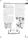
Operate as follows:
>
Position the appliances in front of the installation
area, leaving enugh space to operate at their back [ 1 ].
IMPORTANT: the appliances must be level with
one another.
1 – Attach both units to each other at the front
using the 5 white plastic brackets to hold the units
together.
2 – Adjust the units in the back, so that the side
panels are perfectly parallel to each other. There
are visual cues that will aid with alignment.
3 – The gap ( C ) between the units must be the
same at the back and top. Measure the gap on all
edges and adjust if not equal [ 2 ].
4 – Once the gap is consistent on all edges, secure
the brackets. If the gap between the units is not
even, doors will not align properly.
Gap measurements vary according to the types of
units installed. Please refer to the table below for
correct gap measurements.
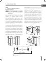
Distance between units (A+B)
CA
18” 24” 30” 36”
B
18” 7/8”
(22 mm)
15/16”
(23,5 mm)
1”
(24,5 mm)
1”
(25,5 mm)
24” 15/16”
(23,5 mm)
1”
(25 mm)
1”
(26 mm)
1 1/16”
(27 mm)
30” 1”
(24,5 mm)
1”
(26 mm)
1 1/16”
(27 mm)
1 1/8”
(28 mm)
36” 1”
(25,5 mm)
1 1/16”
(27 mm)
1 1/8”
(28 mm)
1 1/8”
(29 mm)
1
5.2 Built-in installation of two or more
appliances
4
A
B
C
C
5
2
3

17
EN
Once the appliances have been adjusted and properly
levelled, loosen the two screws holding the sealing plate
in position.
Lower the plate until flush with the floor, and retighten
the screws. This will ensure optimized airflow through
the condenser necessary for proper operation [ 3 ].
> Next join them at the front attaching the
plastic connecting brackets with the supplied screws
[ 4 ] . Attach the bracket on top of the units (if
applicable) as per figure [ 5 ].
> Finish off by mounting the central profile cover onto the
central profiles, by pushing it until a click is heard [ 6 ].
> Once completed, push the units into their final position
[ 7 ].
Always mount front panels on door before pushing the
unit into its final position inside the cutout or structure.
> Check the levelling of the appliance, adjusting its feet
and wheels to correct it.
> Secure the appliance to the adjacent cabinets by fixing
to these the side profiles trims factory-installed on
the appliance [ 8 ]. To make this operation easier
keep the door open.
> Mount the covering frames onto the profiles, first insert
them laterally and then push firmly until a “click” is heard
[ 9 ].
Take care as appliances will be frontheavy
and may tip before they are secured to
the adjacent furniture.
C
A
BB
AA
A
Side and central profiles mounting:
A - plastic connecting
brackets
B - Profile trim cover (side)
C - Profile trim cover
(central).
Appliance
Wall or furniture
7
8
9
6

www.universal.bertazzoni.com
18
6. COMPLETING THE INSTALLATION
2 x
6 x
2 x
6 x
2 x
6 x
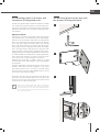
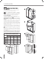
6.1 Anti-tipping safety assembly
If the appliance(s) is not connected through
the side profile trims to secured cabinetry
you must install the anti-tip brackets to en-
sure the product does not fall forward dur-
ing use and cause damage or injury. Failing
to secure the appliance(s) securely will void
any warranty claim attributable to a tipping
situation.
Operate as follows:
>The brackets should be applied as illustrated us-
ing the provided screws If using the anti-tip brack-
ets, lag into wood framing or concrete - drywall will
not hold the weight of appliance.
Place a bracket on the top of the appliance in corre-
spondence to the fixing holes and against the wall
[ 1 ].
>Drill the wall with an 3/8” (8 mm) bit and insert
the expansion plug [ 3 ].
>Reposition the bracket and fix it first to the cabi-
net and then to the wall [ 4 ].
In order to use the anti-tip brackets on the
top compressor models, it will be neces-
sary to temporarily remove the top, metal
ceiling / shield to access the bolting points
for the brackets./ shield to access the bolt-
ing points for the brackets.
152 (6”)
59 (
2
3⁄8
”)
45 (1
5⁄8
”)
1
>Mark up the holes position on the wall [ 2 ].
2
3
4

EN
www.universal.bertazzoni.com
19
36 ’’ 30 ‘‘ 24 ‘‘ 18 ‘‘
A860 (33 7/8”) 740 (29 1/8”) 560 (22”) 410 (16 1/8”)
B>80 (3 1/8")
C10 (3/8”)
50mm (1 7/8")
min 80mm (3 1/8")
6.2 Ventilation
PANEL READY AND PANEL INSTALLED MODELS
A forced air system assures ventilation through a
grille, secured to the unit with magnetic plates,
positioned in the lower front part of the unit [ 1 ].
If the kitchen cabinet includes a kickplate, it must
be placed in a way to ensure a better airflow [ 2 ].
In case of placing a kickplate differently from pic-
ture (2), the kickplate has to be drill at least of an
area equal to 50% of the area delimited by A and
B dimensions in picture [ 3 ].
The condenser must to be cleaned on a regular
basis. In order to do that, the front grille has to be
accessible [ 4 ].
A
B
C
C
1
2
3
4
101.6 (4”)

www.universal.bertazzoni.com
6. COMPLETING THE INSTALLATION
9
Parti retro-illuminate - la parte nera è trasparente
Testo e graÿca
B
C
MOD
bianco EB 61 - 62 ÿli
Fondo o ultimo passaggio:
passaggio di nero coprente 602 -95 ÿli
forato solo per le parti retro illuminate come da disegno “C”
Nomenclature: Grigio Whirlpool
A
Parti retro-illuminate - la parte nera è trasparente
Testo e graÿca
B
C
MOD. 7491TST B02900100
bianco EB 61 - 62 ÿli
Fondo o ultimo passaggio:
passaggio di nero coprente 602 -95 ÿli
forato solo per le parti retro illuminate come da disegno “C”
Nomenclature: Grigio Whirlpool
A
Parti retro-illuminate - la parte nera è trasparente
Testo e graÿca
B
C
MOD. 7491TST B02900100
bianco EB 61 - 62 ÿli
Fondo o ultimo passaggio:
passaggio di nero coprente 602 -95 ÿli
forato solo per le parti retro illuminate come da disegno “C”
Nomenclature: Grigio Whirlpool
A
Parti retro-illuminate - la parte nera è trasparente
Testo e graÿca
B
C
MOD. 7491TST B02900100
bianco EB 61 - 62 ÿli
Fondo o ultimo passaggio:
passaggio di nero coprente 602 -95 ÿli
forato solo per le parti retro illuminate come da disegno “C”
Nomenclature: Grigio Whirlpool
A
Parti retro-illuminate - la parte nera è trasparente
Testo e graÿca
B
C
MOD. 7491TST B02900100
bianco EB 61 - 62 ÿli
Fondo o ultimo passaggio:
passaggio di nero coprente 602 -95 ÿli
forato solo per le parti retro illuminate come da disegno “C”
Nomenclature: Grigio Whirlpool
A
Parti retro-illuminate - la parte nera è trasparente
Testo e graÿca
B
C
MOD. 7491TST B02900100
bianco EB 61 - 62 ÿli
Fondo o ultimo passaggio:
passaggio di nero coprente 602 -95 ÿli
forato solo per le parti retro illuminate come da disegno “C”
Nomenclature: Grigio Whirlpool
A
Parti retro-illuminate - la parte nera è trasparente
Testo e graÿca
B
C
MOD. 7491TST B02900100
bianco EB 61 - 62 ÿli
Fondo o ultimo passaggio:
passaggio di nero coprente 602 -95 ÿli
forato solo per le parti retro illuminate come da disegno “C”
Nomenclature: Grigio Whirlpool
A
Parti retro-illuminate - la parte nera è trasparente
Testo e graÿca
B
C
MOD. 7491TST B02900100
bianco EB 61 - 62 ÿli
Fondo o ultimo passaggio:
passaggio di nero coprente 602 -95 ÿli
forato solo per le parti retro illuminate come da disegno “C”
Nomenclature: Grigio Whirlpool
A
Parti retro-illuminate - la parte nera è trasparente
Testo e graÿca
B
C
MOD
bianco EB 61 - 62 ÿli
Fondo o ultimo passaggio:
passaggio di nero coprente 602 -95 ÿli
forato solo per le parti retro illuminate come da disegno “C”
Nomenclature: Grigio Whirlpool
A
Parti retro-illuminate - la parte nera è trasparente
Testo e graÿca
B
C
Fondo o ultimo passaggio:
passaggio di nero coprente 602 -95 ÿli
forato solo per le parti retro illuminate come da disegno “C”
Nomenclature: Grigio Whirlpool
A
EnglishFrançais
6.3 Post installation control
Check that the front levelling feet have been pro-
perly installed.
Check that the connection to the water system
does not have any leaks and that the shut-off valve
is easily accessible.
Check that the electrical connection is correctly
installed and that the socket and / or breaker are
easily accessible.
Check the perfect alignment of the appliance
with adjacent structures.
Check that all adhesive tape and external or in-
ternal temporary protective devices have been re-
moved.
Check the perfect closing of the doors and the
smooth sliding of the drawers and shelves.
6.4 Start up
>To start the appliance, connect the plug to the
electrical mains: at this point, when opening the
door, the control panel will usually visualize the
message “Stand by”, and all the panel keys will
be off
>To turn on all the appliance compartments,
press the Unit button for three seconds. The
display will show the message “Initial test” for
approximately 2 minutes. After this phase the
compressors will start up and remain on until the
compartment set temperatures are achieved.. Do
bear in mind that this condition could last several
hours during which time the display will continue
to flash the ‘Start Up Phase’ message.
>If the appliance is provided with an Ice Maker,
prior to switching it on make sure that the water
filter cartridge is installed (unless water supply
source is already filtered by other means such as
reverse osmosis).
>Purge air from the water lines by performing
the ‘Manual Clean’ function from the Menu-
>Functions->Water Filter options. You may need
to complete this sequence several times until you
stop hearing air sputtering from the ice maker fill
tube (Refer to your Use & Care Manual).
>Once you are satisfied that the system is pur-
ged of air switch the Ice Maker on by touching the
Ice Maker button which will illuminate.
>For further information about the appliance
operation, refer to the User Manual.
If at the fi st start - up the message Stand
by does not appear, but other messages
appear, such as Fridge too warm, Freezer
too warm, or sound signals are activated, it
means that the appliance has already pre-
viously started the cooling process. If this is
the case, deactivate any possible acoustic
signals by pressing the Alarm button, close
the door and wait until the set temperature
is reached.
It is necessary to let the unit reach the correct
temperature before foods are stored inside.
Bertazzoni is constantly researching new way to
improve the features and the design of their pro-
ducts, therefore models are often upgraded and
revised.
20
La page est en cours de chargement...
La page est en cours de chargement...
La page est en cours de chargement...
La page est en cours de chargement...
La page est en cours de chargement...
La page est en cours de chargement...
La page est en cours de chargement...
La page est en cours de chargement...
La page est en cours de chargement...
La page est en cours de chargement...
La page est en cours de chargement...
La page est en cours de chargement...
La page est en cours de chargement...
La page est en cours de chargement...
La page est en cours de chargement...
La page est en cours de chargement...
La page est en cours de chargement...
La page est en cours de chargement...
La page est en cours de chargement...
La page est en cours de chargement...
La page est en cours de chargement...
La page est en cours de chargement...
La page est en cours de chargement...
La page est en cours de chargement...
La page est en cours de chargement...
La page est en cours de chargement...
La page est en cours de chargement...
La page est en cours de chargement...
La page est en cours de chargement...
La page est en cours de chargement...
La page est en cours de chargement...
La page est en cours de chargement...
La page est en cours de chargement...
La page est en cours de chargement...
La page est en cours de chargement...
La page est en cours de chargement...
La page est en cours de chargement...
La page est en cours de chargement...
La page est en cours de chargement...
La page est en cours de chargement...
La page est en cours de chargement...
-
 1
1
-
 2
2
-
 3
3
-
 4
4
-
 5
5
-
 6
6
-
 7
7
-
 8
8
-
 9
9
-
 10
10
-
 11
11
-
 12
12
-
 13
13
-
 14
14
-
 15
15
-
 16
16
-
 17
17
-
 18
18
-
 19
19
-
 20
20
-
 21
21
-
 22
22
-
 23
23
-
 24
24
-
 25
25
-
 26
26
-
 27
27
-
 28
28
-
 29
29
-
 30
30
-
 31
31
-
 32
32
-
 33
33
-
 34
34
-
 35
35
-
 36
36
-
 37
37
-
 38
38
-
 39
39
-
 40
40
-
 41
41
-
 42
42
-
 43
43
-
 44
44
-
 45
45
-
 46
46
-
 47
47
-
 48
48
-
 49
49
-
 50
50
-
 51
51
-
 52
52
-
 53
53
-
 54
54
-
 55
55
-
 56
56
-
 57
57
-
 58
58
-
 59
59
-
 60
60
-
 61
61


