
Henny Penny
Cold Express Case
Model CEC-103
Model CEC-104
Model CEC-106
Model CEC-108
OPERATOR’S MANUAL


Model CEC-103, 104, 106, 108
LIMITED WARRANTY FOR HENNY PENNY APPLIANCES
Subject to the following conditions, Henny Penny Corporation makes the following limited warranties to the
original purchaser only for Henny Penny appliances and replacement parts:
NEW EQUIPMENT: Any part of a new appliance, except lamps and fuses, which proves to be defective
in material or workmanship within two (2) years from date of original installation, will be repaired or replaced
without charge F.O.B. factory, Eaton, Ohio, or F.O.B. authorized distributor. To validate this warranty, the
registration card for the appliance must be mailed to Henny Penny within ten (10) days after installation.
REPLACEMENT PARTS: Any appliance replacement part, except lamps and fuses, which proves to be
defective in material or workmanship within ninety (90) days from date of original installation will be repaired
or replaced without charge F.O.B. factory, Eaton, Ohio, or F.O.B. authorized distributor.
The warranty for new equipment and replacement parts covers only the repair or replacement of the defective
part and does not include any labor charges for the removal and installation of any parts, travel or other expenses
incidental to the repair or replacement of a part.
EXTENDED FRYPOT WARRANTY: Henny Penny will replace any frypot that fails due to manufacturing or
workmanship issues for a period of up to seven (7) years from date of manufacture. This warranty shall not cover
any frypot that fails due to any misuse or abuse, such as heating of the frypot without shortening.
0 TO 3 YEARS: During this time, any frypot that fails due to manufacturing or workmanship is-
sues will be replaced at no charge for parts, labor, or freight. Henny Penny will either install a new
frypot at no cost or provide a new or reconditioned replacement fryer at no cost.
3 TO 7 YEARS: During this time, any frypot that fails due to manufacturing or workmanship is-
sues will be replaced at no charge for the frypot only. Any freight charges and labor costs to install
the new frypot as well as the cost of any other parts replaced, such as insulation, thermal sensors,
high limits, fittings, and hardware, will be the responsibility of the owner.
Any claim must be presented to either Henny Penny or the distributor from whom the appliance was purchased.
No allowance will be granted for repairs made by anyone else without Henny Penny’s written consent. If damage
occurs during shipping, notify the sender at once so that a claim may be filed.
THE ABOVE LIMITED WARRANTY SETS FORTH THE SOLE REMEDY AGAINST HENNY PENNY
FOR ANY BREACH OF WARRANTY OR OTHER TERM. BUYER AGREES THAT NO OTHER REMEDY
(INCLUDING CLAIMS FOR ANY INCIDENTAL OR CONSEQUENTIAL DAMAGES) SHALL BE AVAIL-
ABLE.
The above limited warranty does not apply (a) to damage resulting from accident, alteration, misuse, or abuse;
(b) if the equipment’s serial number is removed or defaced; or (c) for lamps and fuses. THE ABOVE LIMITED
WARRANTY IS EXPRESSLY IN LIEU OF ALL OTHER WARRANTIES, EXPRESS OR IMPLIED, INCLUD-
ING MERCHANTABILITY AND FITNESS, AND ALL OTHER WARRANTIES ARE EXCLUDED. HENNY
PENNY NEITHER ASSUMES NOR AUTHORIZES ANY PERSON TO ASSUME FOR IT ANY OTHER OB-
LIGATION OR LIABILITY.
FM01-877-C
Revised 02-09-06

Model CEC-103, 104, 106, 108
TABLE OF CONTENTS
Section Page
Section 1. INTRODUCTION ...................................................................................................................1-1
1-1. Henny Penny Cold Express Case................................................................................1-1
1-2. Features .......................................................................................................................1-1
1-3. Proper Care ................................................................................................................. 1-1
1-4. Assistance.................................................................................................................... 1-1
1-5. Safety........................................................................................................................... 1-2
Section 2. INSTALLATION......................................................................................................................2-1
2-1. Introduction ..................................................................................................................2-1
2-2. Unpacking .................................................................................................................... 2-1
2-3. Electrical ......................................................................................................................2-2
2-4. Location .......................................................................................................................2-3
2-5. Refrigerant Information ............................................................................................... 2-3
2-6. Compressor size...........................................................................................................2-3
2-7. Drain Connection ......................................................................................................... 2-3
2-8. Foot Print Drawing ...................................................................................................... 2-4
2-9. Flourescent Lighting..................................................................................................... 2-4
Section 3. OPERATION............................................................................................................................3-1
3-1. Introduction ..................................................................................................................3-1
3-2. Operating Controls .......................................................................................................3-1
3-3. Basic Operation ...........................................................................................................3-3
3-4. Cleaning .......................................................................................................................3-3
3-5. Programming................................................................................................................3-5
Wiring Diagram - 120 Volt ........................................................................................................3-7
Wiring Diagram - 240 Volt ........................................................................................................3-8
GLOSSARY .............................................................................................................................G-1
Distributors List - Domestic and International
i 303

Model CEC-103, 104, 106, 108
1-1. COLD EXPRESS CASE The Henny Penny cold express cases are self-serve units, designed
to hold chilled or refrigerated products. The units are electronically
controlled for easy use and for consistent operation.
1-2. FEATURES • 4 or 8 adjustable, scratch resistant, steel shelves
• Electronic controls
• Fluorescent lighting on each shelf
• Low speed air circulation
• Easily cleaned and maintained
• High horsepower compressor, mounted in recessed base
• Self-serve units
• Insulated-well with high pressure injected polyurethane foam
• Automatic defrost cycles
• Air curtain
1-3. PROPER CARE As in any unit of food service equipment, the Henny Penny cold
express case does require care and maintenance. Requirements for
the maintenance and cleaning are contained in this manual and must
become a regular part of the operation of the unit at all times.
1-4. ASSISTANCE Should you require outside assistance, just call your local indepen-
dent Henny Penny distributor in your area, or call Henny Penny
Corp. 1-800-417-8405 toll free or 1-937-456-8405.
503 1-1
SECTION 1. INTRODUCTION

Model CEC-103, 104, 106, 108
1-5. SAFETY The Henny Penny cold express cases have many safety features
incorporated. However, the only way to ensure a safe operation
is to fully understand the proper installation, operation, and
maintenance procedures. The instructions in this manual have
been prepared to aid you in learning the proper procedures.
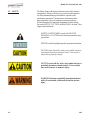
Where information is of particular importance or safety related,
the words NOTICE, CAUTION, and WARNING, are used. Their
usage is described below.
SAFETY ALERT SYMBOL is used with DANGER,
WARNING, or CAUTION which indicates a personal injury
type hazard.
NOTICE is used to highlight especially important information.
CAUTION used without the safety alert symbol indicates
a potentially hazardous situation which, if not avoided,
may result in property damage.
CAUTION used with the safety alert symbol indicates a
potentially hazardous situation which, if not avoided,
may result in minor or moderate injury.
WARNING indicates a potentially hazardous situation
which, if not avoided, could result in death or serious
injury.
1-2 303

Model CEC-103, 104, 106, 108
2-1. INTRODUCTION This section provides the installation and unpacking instructions for
Henny Penny cold express case.
Installation of this unit should be performed only by a
qualified service technician.
Do not puncture the unit with any objects such as
drills or screws, or component damage or electrical
shock could result.
2-2. UNPACKING The Henny Penny cold express case has been tested, inspected,
and expertly packed to insure arrival at its destination in the best
possible condition. The grids are packed separately inside the
unit. The cabinet rests on a wooden skid and is then packed inside
a heavy cardboard carton with sufficient padding to withstand
normal shipping treatment.
To avoid damage to the components, do not lay the unit
on its side. If the unit has been on its side, the unit must
be in an upright position for at least 4 hours before power
is applied to the unit.
Check all components, for signs of being loose or dam-
aged, and make sure the system has refrigerant.
When moving the cold express case be careful not to
damage the refrigerant circuit.
Any shipping damage should be noted in the presence
of the delivery agent and signed prior to his or her
departure.
To remove the Henny Penny cold case from the carton:
1. Carefully cut banding straps.
2. Lift the carton off the unit.
3. Lift the unit off the skid.
303 2-1
SECTION 2. INSTALLATION

Model CEC-103, 104, 106, 108
2-2. UNPACKING
Take care when moving the unit to prevent personal
injury or damage to the refrigeration system. The units
weigh between 550 lbs. (250 kg) and 1200 lbs.
(544 kg).
4. Peel off any protective covering from exterior of the cabinet.
5. Install the shelves into unit.
6. Your cold express case is now ready for operation.
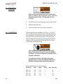
2-3. ELECTRICAL The cold express case is available as a 120 VAC, or 240 VAC,
60 Hz., single phase unit, both for domestic and international use.
(See table below) The data plate, located on the left side of the
unit, specifies the correct electrical supply. The cold express
cases are shipped with cord and plug, and requires a grounded
receptacle with a separate electrical line protected by a fuse or
circuit breaker of the proper rating.
This unit must be adequately and safely grounded.
Refer to local electrical codes for correct grounding
procedures. If unit is not adequately grounded, electri-
cal shock could result.
To avoid electrical shock, this appliance must be
equipped with an external circuit breaker which will
disconnect all ungrounded (unearthed) conductors.
Refer to the table below for electrical ratings:
Model No. Volts Amps Phase Max. Fuse Size
CEC-103 120 18.3 1 20
CEC-104 240 12.6 1 20
CEC-106 240 10.9 1 30
CEC-108 240 16.1 1 30
(Continued)
2-2 503

Model CEC-103, 104, 106, 108
303 2-3
2-5. REFRIGERANT Design Pressure
INFORMATION High Low
CEC-103 R22 2 lbs (.9 kg) 175psig 30 psig
(12.1 bar) (2.1 bar)
CEC-104 R22 5 lbs (2.3 kg) 175psig 30 psig
(12.1 bar) (2.1 bar)
CEC-106 R22 6 lbs (2.7 kg) 175psig 30 psig
(12.1 bar) (2.1 bar)
CEC-108 R22 6 lbs (2.7 kg) 175psig 30 psig
(12.1 bar) (2.1 bar)
2-6. COMPRESSOR SIZE CEC-103 CEC-104
1/2 Horsepower 3/4 Horsepower
CEC-106 CEC-108
1-1/4 Horsepower 1-3/4 Horsepower
Refrigerant Type Amount of Refrig.
2-7. DRAIN CONNECTION Cold express cases do not require a plumbed drain.
2-4. LOCATION Place the cold express cases in an area where product can be
loaded and unloaded without interruption. For proper operation,
level the unit by adjusting the bolts under the case.
For maximum efficiency, units should be operated in an air-condi-
tioned environment, with maximum air temperature of 75° F
(24° C), and 55% relative humidity.
Wait at least 4 hours before plugging the unit into an
electrical supply. The gases and oils in the refrigeration
system need to settle before operating the compressor, or
damage to the compressor could result.

Model CEC-103, 104, 106, 108
2-8. FOOT PRINT DRAWING
CEC MODELS
DRAIN/ELECTRICAL BOX
2-4 1101
36
34
Ø1-5/8
Drain
(Egoutten dans la
pan sous le comptoir)
Refrigeration
Electrical
20
14-3/8
48-1/2
34
32
2
20
Ø1-5/8
Drain
(Egoutten dans la
pan sous le comptoir)
Refrigeration
Electrical
2
72-1/4
34
32
2
2
Ø1-5/8
Drain
(Egoutten dans la
pan sous le comptoir)
Refrigeration
2
Electrical
20
14-3/8
96
20
14-3/8
Drain
(Egoutten dans la
pan sous le comptoir)
Refrigeration
Electrical
Ø1-5/8
3-3/8
3-3/8
3-3/8
3-3/8
2
32
34
2
CEC-103 CEC-104
CEC-106 CEC-108
2
14-3/8
2-9. FLOURESCENT LIGHTING No. of Lights and Size
Model Canopy Shelves
CEC-103 1 - 24 in. (61.0 cm) 4 - 24 in. (61.0 cm)
CEC-104 1 - 36 in. (91.4 cm) 4 - 36 in. (91.4 cm)
CEC-106 1 - 24 in. (61.0 cm) 8 - 24 in. (61.0 cm)
1 - 36 in. (91.4 cm)
CEC-108 1 - 36 in. (91.4 cm) 8 - 36 in. (91.4 cm)
1 - 48 in. (122 cm)

Model CEC-103, 104, 106, 108
3-1. INTRODUCTION This section provides explanations of all controls, along
with operating procedures and daily maintenance. Read the
Introduction, Installation and Operation Sections before
operating the unit.
Wait at least 4 hours before plugging the unit into an
electrical supply. The gases and oils in the refrigeration
system need to settle before operating the compressor, or
damage to the compressor could result.
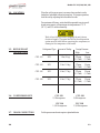
3-2. OPERATING CONTROLS Refer to figure 3-1.
Fig. Item Description Function
No. No.
3-1 1 Power Switch A rocker switch that turns electrical power, off and on to
the unit
3-1 2 Digital Display Shows the temperatures, the time (in a timing cycle), and
the information in the Technical Mode
3-1 3 The up and defrost button is used to increase setpoint
values, as well as programming values; also, automatic
defrost cycles are programmed in the controls, but to
manually start a defrost cycle, press and hold for 3
seconds to start a manual defrost cycle
(“DEF/SET’ shows in display)
3-1 4 The down button is used to decrease setpoint values, as
well as programming values
3-1 5 Press the set button to view the setpoint temperature, or
hold it for it for 4 seconds to enter the Program Mode;
once in the Program Mode, press to view other
parameter setpoints; press , along with and
to change the parameters.
SECTION 3. OPERATION
3-1 303

Model CEC-103, 104, 106, 108
Figure 3-1
3 2 1
4 5
1001 3-2
3-2. OPERATING CONTROLS
(Continued)

Model CEC-103, 104, 106, 108
3-3. BASIC OPERATION 1. Turn power switch to ON position.
2. Wait for temperature to reach operating temperature,
36 to 38° F (2.2 to 3.3° C).
3. Place chilled, prepackaged product into case.
Do not block the air return and air discharge vents with
product. Product temperatures may become unsafe,
and increase operating costs.
Do not use mechanical devices or other means to quicken
the defrosting process, other than those recommended by
the manufacturer, or damage to the unit could result.
Do not use electrical appliances inside the food storage
areas of the unit, unless they are of the type recommended
by the manufacturer, or damage to the unit could result.
3-4. CLEANING Weekly:
1. Remove all electrical power supplied to the unit by unplug-
ging the power cord from the wall, or by turning off the
wall circuit breaker.
2. Clean exterior surfaces with a soft cloth, soap and water.
Do not use steel wool, other abrasive cleaners or
cleaners/sanitizers containing chlorine, bromine, iodine
or ammonia chemicals, as these will deteriorate the
stainless steel, and glass material, and shorten the life of
the unit.
Do not use a water jet (pressure sprayer) to clean the
unit, or component failure could result.
3. Clean around the electronic controls with a soft, damp cloth.
4. Reconnect the electrical power to the unit and unit is now
ready for operation.
3-3 303

Model CEC-103, 104, 106, 108
3-4. CLEANING Every 3 Months:
(Continued) 1. Remove all electrical power supplied to the unit by unplugging
the power cord from the wall, or by turning off the
wall circuit breaker.
2. Remove all product from the unit.
3. Remove the racks and pans from the unit and clean with
soap and water at a sink.
4. Clean interior surfaces with a soft cloth, soap and water.
Do not use steel wool, other abrasive cleaners or
cleaners/sanitizers containing chlorine, bromine, iodine
or ammonia chemicals, as these will deteriorate the
stainless steel, and glass material, and shorten the life of
the unit.
Do not use a water jet (pressure sprayer) to clean the
unit, or component failure could result.
5. Clean around light fixtures with a soft, damp cloth.
6. Reconnect the electrical power to the unit and unit is now
ready for operation.
303 3-4

Model CEC-103, 104, 106, 108
3-5. PROGRAMMING 1. Press and hold for 4 seconds. The “DEF/SET” light
flashes in display.
Temperature Setpoint
2. Press the or to change the temperature setpoint,
within 5 seconds. After 5 seconds, the last entered setpoint
stays in memory.
Other Parameters
3. Press to access the other parameters. Each press of the
accesses the next parameter. The parameters are:
d: (differential) -15...15 range
LS: (lower set) lower user-access setpoint limit.
(-55...99 range)
The units are programmed to defrost 3 times a day, at 8
hour intervals, lasting 30 minutes. Do not program the
setpoint temperature below 33° F (1° C), or ice buildup
will decrease efficiency.
HS: (higher set) upper user-access setpoint limit
(-55...99 range)
CA: (calibration) temperature readout offset to allow for
possible error due to probe location (-15...15 range)
rP: (relay protection) select relay status in case of probe
defect.
“on” = compressor ON in case of probe defect
“of” = compressor OFF in case of probe defect
PS: (protection system-short cycle) select type of compressor
protection desired (the actual time delay is set with the next
parameter):
“0”=delay before start - in seconds
“1”=delay before start - in minutes
“2”=delay after stop - in minutes
“3”=delay between starts - in minutes
Pt: (protection time) select the time delay setting for compres-
sor protection. (0...31 range)
3-5 303

Model CEC-103, 104, 106, 108
3-6. PROGRAMMING dS: (defrost system (computation)) dF=digifrost feature;
Continued defrost start time based on total compressor running time;
rt=real time; defrost start frequency, based on real time
dI: (defrost interval) defrost frequency in hours, based on the
selection of “dS”
dE: (defrost endurance) total (maximum) length of a defrost
cycle, expressed in minutes (1...99 range)
dL: (display lock) temperature display is locked during a
defrost cycle (0...31 range)
“n”=no (readout continues to display the actual tempera-
ture, even during a defrost cycle
“y”=yes (readout is locked)
dr: (display readout) select the type of visualization in case of
temperature display lock during defrost (see prameter dL);
“C”=the temperature displayed at the start of a defrost is
locked and does not change during this cycle
“dF”=during the defrost “dF” is displayed
do: (defrost at power on) selects whether or not, the system
goes through the defrost cycle at start-up (or after power
failure)
“n”=no
“y”=yes
dd: (defrost delay at power on) delay of defrost cycle, in
minutes (0...99 range)
Error Code “E1”
This is the only error code in these controls. It indicates a tempera-
ture sensor failure, such as, a shorted sensor, a sensor break, or
absence of sensor.
It can also indicate an under-range in the system temperature (-55).
In case of an over-range in the system temperature, “99” shows first
in the display, followed by “E1”.
303 3-6

Model CEC-103, 104, 106, 108
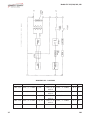
3-7 102
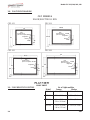
ELECTRICAL RATINGS
MODEL COMPRESSOR FANS LIGHT M C A M F S
CEC-103 120V / 6.7 AMPS ½ HP 120V / 0.36 120V / 0.5 AMPS 18.3 20
AMPS
CEC-104 240V / 7.1 AMPS ¾ HP 120V / 0.60 120V / 0.9 AMPS 12.6 20
AMPS
CEC-106 240V / 7.1 AMPS 1 ¼ HP 120V / 0.72 120V / 0.9 AMPS 10.9 30
AMPS
CEC-108 240V / 8.0 AMPS 1 ¾ HP 120V / 1.08 120V / 1.4 AMPS 16.1 30
AMPS

Model CEC-103, 104, 106, 108
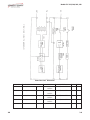
102 3-8
ELECTRICAL RATINGS
MODEL COMPRESSOR FANS LIGHT M C A M F S
CEC-103 120V / 6.7 AMPS ½ HP 120V / 0.36 120V / 0.5 AMPS 18.3 20
AMPS
CEC-104 240V / 7.1 AMPS ¾ HP 120V / 0.60 120V / 0.9 AMPS 12.6 20
AMPS
CEC-106 240V / 7.1 AMPS 1 ¼ HP 120V / 0.72 120V / 0.9 AMPS 10.9 30
AMPS
CEC-108 240V / 8.0 AMPS 1 ¾ HP 120V / 1.08 120V / 1.4 AMPS 16.1 30
AMPS

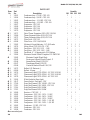
Model CEC-103, 104, 106, 108
Item Part Quantity
No. No. Description 103 104 106 108
1 24261 Condenser Assy. -1/2 HP - CEC-103 1 - - -
1 24264 Condenser Assy. -3/4 HP - CEC-104 - 1 - -
1 24265 Condenser Assy. -1-1/4 HP - CEC-106 - - 1 -
1 24266 Condenser Assy. -1-3/4 HP - CEC-108 - - - 1
2 24267 Evaporator - CEC-103 1 - - -
2 24268 Evaporator - CEC-104 - 1 - -
2 24269 Evaporator - CEC-106 - - 1 -
2 24270 Evaporator - CEC-108 - - - 1
√√
√√
√ 3 24271 Valve-Therm. Expansion (R22)-CEC-103/104 1 1 - -
√√
√√
√ 3 23980 Therm. Expansion Valve (R22)-CEC-106 - - 1 -
√√
√√
√ 3 24272 Therm. Expansion Valve (R22)-CEC-108 - - - 1
√√
√√
√ 4 24273 Filter-Drier - CEC-103 1 - - -
√√
√√
√ 4 66998 Filter-Drier - CEC-104/106/108 1 - - -
5 23982 Moisture & Liquid Indicator - 1/4”-SAE-male 1111
√√
√√
√ 6 24274 Motor-Morril 115V, 9W-CW - CEC - 1 2 2
√√
√√
√ 6 26991 Fan Motor - CEC-103, 115V - 16W 1 - - -
√√
√√
√ 6 26993 Fan Motor - CEC-10X, 230V - 16W - 1 1 1
7 23984 Fan Blade - 8”- 20 degree pitch, CW-Hubless 1122
8 23986 Electronic Control-Eliwell-Complete-12V-EWPC961 1111
√√
√√
√ 23985 Electronic Control-Eliwell-Only 1111
65045 Front cover & Bezel-Eliwell Control - F 1111
√√
√√
√ 65046 Sensor/Probe-Eliwell-120V/12V 1111
√√
√√
√ 65047 Transformer-Eliwell-120V12V 1111
65048 Control & Bracket-Eliwell-120V/12V 1111
√√
√√
√ 9 24275 Ballast-G..E. Electronic 1 1 1 1
√√
√√
√ 9 66999 Ballast - 4 Lamp 1 1 1 1
√√
√√
√ 10 24276 Fluorescent Light F17T8-SPX41 - 24”-CEC-103/106 1 - 1 -
√√
√√
√ 10 24277 Fluorescent Light F25T8-SPX41 - 36”-CEC-104/108 - 1 - 1
√√
√√
√ 10 24278 Fluorescent Light F32T8-SPX41 - 48”-CEC-108 - - - 1
11 23993 White Socket for Neon Light 2244
√√
√√
√ 12 24147 Power Switch - Fan/Light - 125V 1111
√√
√√
√ 13 27269 Evap. Pan Element 120V 1000W - CEC-104 - 1 - -
√√
√√
√ 13 27413 Evap. Pan Element 120V 480W - CEC-103 1 - - -
√√
√√
√ 13 27414 Evap. Pan Element 240V 1000W - 1 1 -
√√
√√
√ 13 27415 Evap. Pan Element 240V 1500W - - - 1
14 26989 Receiver - CEC-10X 1 1 1 1
15 26982 Compressor - CEC-103 - 120V - 1/2 HP 1 - - -
15 26992 Compressor - CEC-104 - 240V - 3/4 HP - 1 - -
15 26999 Compressor - CEC-104 - 120V - 3/4 HP - 1 - -
15 26995 Compressor - CEC-106 - 240V - 1-1/4 HP - - 1 -
15 26994 Compressor - CEC-108 - 240V - 1-3/4 HP - - - 1
16 26982 Condensor - 1/2 HP - CEC-103 1 - - -
16 26996 Condenser - CEC-106- - 1 -
16 26998 Condenser - CEC-108- - - 1
√√
√√
√recommended parts
PARTS LIST
3-9 206

Model CEC-103, 104, 106, 108
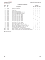
PARTS LIST (Continued)
Item Part Quantity
No. No. Description 103 104 106 108
17 26990 Fan Blade - Condenser 1 1 1 1
18 65234 Glass - Side 2 2 2 2
19 65926 Deck - Black Interlocking - 1 1 1
19 65927 Deck - Black Interlocking - CEC-103 1 - - -
19 65928 Deck - Black Interlocking - Common 1 1 1 1
20 65929 Assy - Shelf - CEC-103 - White 4 - - -
20 65930 Assy - Shelf - CEC-104 - White - 4 - -
20 65931 Assy - Shelf - CEC-106 - White - - 4 -
20 65932 Assy - Shelf - CEC-108 - White - - - 4
20 66049 Assy - Shelf - CEC-103 - Black 4 - - -
20 66050 Assy - Shelf - CEC-104 - Black - 4 - -
20 66051 Assy - Shelf - CEC-106 - Black - - 4 -
20 66052 Assy - Shelf - CEC-108 - Black - - - 4
20 66926 Assy - Shelf w/o Lights - CEC-106 - - 4 -
21 66969 Stop - Plastic Product - CEC-106 - 1-1/2 - - 4 -
22 66996 Harness - Single Receptacle - Female - CEC-104 - 1 - -
23 67053 Harness - Single Receptacle - Male - CEC-104 - 1 - -
24 67215 Cap - Protective End - Fluorescent Light 2 2 4 4
√√
√√
√ 25 67279 Relay - Switching - 120V - CEC-103 (IFI# 1054087) 1 - - -
√√
√√
√ 25 67280 Relay - Switching-240V-CEC-104/106/108 (IFI# 1054090) - 1 1 1
√√
√√
√recommended parts
206 3-10
La page charge ...
-
 1
1
-
 2
2
-
 3
3
-
 4
4
-
 5
5
-
 6
6
-
 7
7
-
 8
8
-
 9
9
-
 10
10
-
 11
11
-
 12
12
-
 13
13
-
 14
14
-
 15
15
-
 16
16
-
 17
17
-
 18
18
-
 19
19
-
 20
20
-
 21
21


Henny Penny CEC-104 Mode d'emploi
- Taper
- Mode d'emploi
dans d''autres langues
Documents connexes
Autres documents
-
Miller FILTAIR INDUSTRIAL COLLECTOR SERIES (460 VOLT) Le manuel du propriétaire
-
Miller MJ315007D Le manuel du propriétaire
-
-
Alpha XM3.1-HP Broadband UPS Technical Manual
-
Samsung HT-AS720 Manuel utilisateur
-
Samsung HT-AS720 Manuel utilisateur
-
Warmup DWM-240-350 Mode d'emploi