Bosch B18IF800SP/01 Guide d'installation
- Catégorie
- Congélateurs
- Taper
- Guide d'installation
Ce manuel convient également à


en-us
3
en Table of Contents
enOperating instructions
Important Safety Instructions ..................................... 4
IMPORTANT .................................................................... 4
General............................................................................. 4
Definition .......................................................................... 4
Installation options............................................................ 5
Individual appliance ....................................................... 5
Side-by-Side..................................................................... 5
Individual appliances with partition............................. 5
Individual appliance at the end of the kitchen.......... 5
Installation .................................................................... 6
Installation room ............................................................. 6
Climatic classes.............................................................. 6
Stable installation ........................................................... 6
Installation niche............................................................. 6
Furniture ........................................................................... 6
Floor.................................................................................. 6
Aligning the appliance................................................... 6
Connecting the power.................................................. 7
Connecting the water................................................... 7
Dimensions of the installation niche.......................... 8
Required accessories and tools ................................. 9
Supplied accessories ................................................... 9
Optional accessories .................................................... 9
Other required accessories ......................................... 9
Miscellaneous ................................................................ 9
Tools ................................................................................ 9
Installation instructions............................................. 10
1. Checking the installation niche ........................ 10
2. Removing the packaging .................................. 10
3. Transport of the appliance ................................ 11
4. Installation preparation ....................................... 11
5. Special installation .............................................. 11
1. Attaching the anti-tip-brackets ................. 12
2. Attaching an alternative anti-tip device .. 13
3. Attaching an edge protection .................. 13
1. Pushing the appliance into
the installation niche ................................. 14
2. Aligning the appliance in
the installation niche ................................. 15
3. Attaching the appliance to
the installation niche................................... 16
1. Attaching the toe kick panel .................... 17
2. Aligning the base panel ........................... 17
3. Switching the appliance ON .................... 18
4. Preparing the door panels ....................... 18
5. Loading the appliance door .................... 18
6. Removing the installation support part . 18
7. Attaching the adjusting rail to
the door panel ............................................ 18
8. Attaching the fixation strips
to the door panel ....................................... 19
9. Attaching the door panel .......................... 20
10. Attaching the lower bracket ..................... 21
11. Attaching the strips ................................... 22
12. Mounting the air separator ...................... 22
13. Adjusting the door spring ........................ 22
Special installation..................................................... 23
Changing over the door hinges...................... 23
Removing/changing over the sealing mat ... 26
Side-by-Side installation ................................... 26
Preparing to connect the water ...................... 28
Connecting the water to the appliance ......... 28
Adjusting the door opening angle.................. 28

, Important Safety Instructions
READ AND SAVE THESE INSTRUCTIONS!
en-us
4
Important Safety Instructions
These mounting instructions are designed to help you
install your new appliance.
The manufacturer cannot be held liable for mounting
which has been improperly carried out. We recommend
that you allow a qualified specialist to set up and switch
the appliance on for the first time.
Following all information and keeping to the instructions
are preconditions for mounting and switching the
appliance on safely for the first time.
Keep the mounting instructions safe for use later on.
Before setting up and switching the appliance on for
the first time, read the mounting instructions fully and
thoroughly.
, WARNING:
These appliances are top-heavy and must be
secured to prevent the possibility of tipping
forward.
Anti-tip protection is required.
Keep doors closed until the appliance is
completely installed and secured per installation
instructions.
Due to the weight and size of this appliance, and
to reduce the risk of personal injury or damage
to the product – TWO PEOPLE ARE REQUIRED
FOR PROPER INSTALLATION.
This appliance must be properly grounded.
See chapter “Connecting the power”.
Use this appliance only for its intended purpose.
Immediately repair or replace electric service
cords that become frayed or damaged.
Unplug the appliance or switch off the fuse
before cleaning or making repairs.
Repairs should be made by a qualified service
technician.
, CAUTION:
Installation of this appliance requires basic
mechanical, carpentry and plumbing skills.
Proper installation is the responsibility of the
installer.
Product failure due to improper installation is not
covered under the Appliance Warranty.
See the Owner's Manual for warranty information.
IMPORTANT
Save these instructions for local inspector's use.
Observe all governing codes and ordinances.
Note to Installer – Be sure to leave these instructions
with the Consumer.
Note to Consumer – Keep these instructions with your
Owner's Manual for future reference.
General
These installation instructions are intended for use by
qualified installers. All connections for water, electrical
power and grounding must comply with local codes
and ordinances and be made by licensed personnel
when required. In the absence of a local code:
■ In the U.S.A., in accordance with the National
Electric Code, ANSI/NFPA70 – latest edition/State
and Municipal codes and/or local codes.
■ In Canada, in accordance with the Canadian
Electric Code C22.1 – latest edition/Provincial
and Municipal codes and/or local codes.
Note:
This is used to draw the user's attention to something in
particular.
Definition
, WARNING:
This indicates that serious injury or death may
result due to non-observance of this warning.
, CAUTION:
This indicates that minor or moderately severe
injury may result due to non-observance of this
warning.

en-us
5
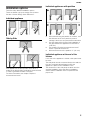
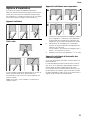
Installation options
There are many different installation options.
These are limited only by the design of the kitchen.
See also “Kitchen Design Quick Reference”.
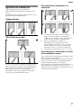
Individual appliance
Side-by-Side
If two appliances are set up next to each other, a
sealing kit for Side-by-Side combination should be used
in order to guarantee a stable connection.
For further information see chapter “Required
accessories and tools”.
Individual appliances with partition
■ When dimensioning the partition for model 4, note
the thickness of the door panels to prevent
damage if the doors are opened at the same time.
■ Use the Heater Kit for Side-by-Side Installation if
the gap between the appliances is less than 6"
(160 mm).
■ See chapter “Required accessories and tools”,
section “Optional accessories”.
■ Minimum thickness of the partition
5
/
8
" (16 mm).
Individual appliance at the end of the
kitchen
If one side of the appliance is visible, a side panel must
be used.
The side panel must be connected firmly to the wall, the
floor and overhead cabinet/fixtures before the
appliance is placed in the installation niche.
The dimensions of the side panel are taken from the
opposite installation niche wall. During installation
ensure that the installation niche is square and the
proper size.

en-us
6
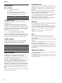
Installation
, WARNING:
Do not install the appliance:
■ outdoors,
■ in an environment with dripping water,
■ in rooms which are less than 32 °F (0 °C).
■ A fully-loaded appliance is very heavy.
Installation room
The appliance should be installed in a dry, well
ventilated space.
The location should not be exposed to the direct
sunlight and should not lie next to a source of heat
such as a cooker or a radiator etc. If installation next to
a source of heat cannot be avoided, either a suitable
insulating plate should be used or you should keep to
the following minimum distances:
■ 1
1
/
4
" (3 cm) to electric or gas cookers.
■ 12" (30 cm) to an oil or coal-fired cooker.
The floor of the installation location must not give way; if
required, reinforce floor. To ensure that the ice maker
functions correctly, the appliance must be upright.
Climatic classes
The climate class can be found on the rating plate.
The climate class indicates within which ambient
temperatures the appliance can be operated.
Stable installation
The appliance is very heavy and has a tendency to tilt
forwards when the appliance door is opened.
The appliance must not be switched on until there is no
possibility of the appliance tilting over.
The safest method of installing the appliance in a stable
position is to use the supplied anti-tilt brackets.
If the installation niche is adequately stable and the
appliance can be attached securely to the upper and
side walls of the niche, it may be possible to dispense
with the anti-tilt brackets. A prerequisite for this is
always a firm connection between the niche and back
wall!
In the case of doubt, the help of architect or specialist
builder should be enlisted.
Installation niche
It is important to keep to the stated dimensions of the
installation niche with a view to trouble-free fitting, and
the subsequent appearance of the kitchen furniture
frontage.
Special care should be taken that the niche has right
angles. The side walls should not exhibit areas that
stick out, projections or unevenness.
You should determine the right angles of the installation
niche with appropriate means, e.g. by measuring
diagonally and by using a spirit level.
The side walls and the upper end of the installation
niche must be at least
5
/
8
" (16 mm) thick.
Furniture
The new appliance is screwed down tightly using parts
of the cabinet and the upper cabinet.
Care should therefore be taken, that all upper cabinets
to which something has been fastened are securely
connected to the subsurface or wall by appropriate
means.
The minimum thickness of the base should be a
minimum of
3
/
4
" (19 mm).
Floor
The subsurface must be level and even in order to
ensure that the appliance is securely installed and
works correctly.
The subsurface must be made from a hard, non-flexible
material.
The floor of the installation space must have the same
height as the rest of the space.
On account of the weight of a fully-laden appliance, it is
necessary to have a bearing subsurface. In the case of
doubt, the help of architect or specialist builder should
be enlisted.
Aligning the appliance
To ensure that the appliance functions correctly, it must
be levelled properly.
If the appliance is not level, water may flow out of the
ice maker, ice cubes may be irregular or the doors may
not close properly.
Refrigerator 30" approx. 1110 Ibs/500 kg
Freezer 18" approx. 560 Ibs/250 kg
Climatic class Permitted ambient temperature
SN 50 °F to 90 °F (+10 °C to 32 °C)
N 61 °F to 90 °F (+16 °C to 32 °C)
ST 61 °F to 100 °F (+16 °C to 38 °C)
T 61 °F to 110 °F (+16 °C to 43 °C)

en-us
7
Connecting the power
, WARNING:
■ Avoid the risk of an electric shock!
■ Insert into a grounded 3-phase socket.
Never remove grounding phase. Do not use
any adapters. Do not use any extension
cables.
■ Non-compliance with these instructions may
result in death, fire or an electric shock.
Improper connection of the protective
conductor may result in an electric shock. If
you are in doubt whether the appliance has
been grounded properly, have the appliance
tested by a qualified electrician or service
technician.
The socket must be near the appliance and also freely
accessible following installation of the appliance.
The appliance complies with protection class I.
Connect the appliance to 115 V/60 Hz alternating
current via a correctly installed socket with protective
conductor. The socket must be fused with a 10 to 16 A
fuse.
The appliance comes with a UL registered 3-wire power
cord. The appliance requires a 3-pole socket. Please
observe the following table with regard to this:
(*) incl. Ice Maker
Check on the rating plate whether the indicated voltage
and current type correspond with the values of your
power supply. The location of the rating plate can be
found in the chapter “Customer service”.
, WARNING:
Never connect the appliance to electronic energy
saver plugs. Our appliances can be used with
mains and sine-controlled inverters. Mains-
controlled inverters are used for photovoltaic
systems which are connected directly to the
national grid. Sine-controlled inverters must be
used for isolated applications (e.g. on ships or in
mountain lodges) which are not connected
directly to the national grid.
Connecting the water
, CAUTION:
Only connect the appliance to drinking water!
The water may be connected only by a competent fitter
according to the local regulations of the appropriate
water supply company.
A cold water connection is necessary for operating the
automatic ice maker. The water pressure must be
between 25 and 120 p.s.i. (1,72 and 8,25 bar).
The installation must correspond to the local plumbing
regulations.
A separate shut-off valve should be installed in the cold
water inflow. The shut-off valve should not be located
behind the appliance. It is recommended that you
mount the shut-off valve directly next to the appliance or
at another place which is easily accessible. When
installing the water connection, pay attention to the
permissible installation area for the water mains.
For connection to the drinking water mains use only
water pipes which are suitable for drinking water.
Observe national regulations and the connection
conditions of the local water supply companies.
When installing the water connection, observe the
permitted installation areas for the pipe. For the
permitted installation areas and dimensions see
“Dimensions of the installation niche”.
Maximum outer diameter of the water pipe
(without fittings):
3
/
8
" (9.5 mm).
Appliance Maximum Simultaneous Load
Refrigerator 30" 2.0 Ampere
Freezer 18" (*) 3.5 Ampere

en-us
8
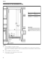
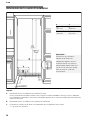
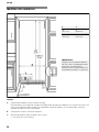
Dimensions of the installation niche
Legend:
X Y
18"
(457 mm)
9"
(229 mm)
30"
(762 mm)
15"
(381 mm)
IMPORTANT!
The side walls of the niche must be
perfectly straight. The furniture return
area has to be at least 4" (100 mm)
deep.
A Area for installation of the water connection
It is recommended the water-box be placed adjacent to the installation niche, so that it can be accessed for
service without uninstalling the appliance. If this is not possible, place the recessed water box within the shaded
area.
B Area for installation of the power connection
C Opening depth of niche, depending on kitchen design
C = 24" (610 mm) minimum

en-us
9
Required accessories and tools
Supplied accessories
■ Installation instructions
■ Operating instructions
■ Installation kit
Optional accessories
Freedom Heater Kit for Side-by-Side Installation
HEATKITB80
If the gap between the appliances is less
than 6" (160 mm).
Other required accessories
Ice maker installation kit
1
/
4
" OD copper line
For connecting appliances which require water, e.g. for
an ice maker.
Maximum outer diameter of the water pipe (without
fittings):
3
/
8
" (9.5 mm).
Miscellaneous
■ Stepladder
■ Dolly, hand truck
■ Hammer drill for drilling holes in wall or floor
■ Bits according suitable for material and in different
sizes
■ Wooden beam (cross section min. 3" x 4") as an
alternative tip protection, length according to the
width of the installation niche
■ Wooden screws in different sizes
■ Thin plywood sheet, particle board or cardboard
to protect the floor from damage
■ Suitable material for covering and protecting
furniture (e.g. protective sheets)
■ Adhesive tape
Note:
Before using, check whether the removed adhesive
tape leaves adhesive residue on the work surfaces!
Otherwise do not use on high-quality work surfaces.
Tools
Cordless screwdriver
Torx bit T20 / T30 +
magnetic holder
Torx screwdriver T20
5
/
16
" (8 mm) hex nut driver
Wood drills in different sizes
Open end wrench
1
/
2
"
(SW 13 mm)
Multigrip pliers
Adjustable wrench
Cutter with adjustable blade
Metal tape measure, folding
rule
Square
Level, length 2' (60 cm) and
4' (1.2 m)
Level, min. 4' (1.2 m) long

en-us
10
Installation instructions
The following installation instructions describe the
installation steps for various appliance types:
■ Refrigerator units
■ Freezer units
■ Freezer units with ice maker
Therefore the diagrams may be a general
representation of your appliance.
Particular reference is made to special installation steps
for individual appliance types.
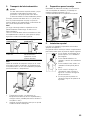
1. Checking the installation niche
, CAUTION:
Use the following check list for a safe and
trouble free installation.
1.
Check the floor.
See chapter “Installation”, section “Floor”.
2.
Check the dimensions of the installation niche,
see chapter “Dimensions of the installation niche”.
3.
Check that the installation niche is square.
4.
Check location of the socket.
See chapter “Connecting the power” and
chapter “Dimensions of the installation niche”.
5.
Check location of the water connection
(only for appliances with ice maker).
See chapter “Connecting the water” and
chapter “Dimensions of the installation niche”.
6.
Check attachment of the adjacent cabinet/fixtures.
All cabinet parts in the vicinity of the appliance
must be connected securely to the wall.
7.
Check that adjacent cabinet/fixtures have
adequate clearance (door opening angle).
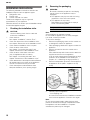
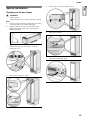
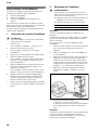
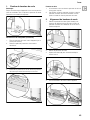
2. Removing the packaging
, WARNING:
Be careful, otherwise people who are helping
may be injured or the appliance may be
damaged!
■ The appliance may tip over while it is being
unpacked or if the doors are opened.
■ The appliance is very heavy.
Data relating to the weight when empty is
found in the following table:
Note:
Check appliance for damage in transit.
Do not install the appliance if it is visibly damaged.
If in doubt, contact your dealer.
To avoid floor damage:
1.
Remove the packaging carton and be careful not
to damage the surface of appliance.
2.
Place packaging cardboard or plywood under the
appliance.
3.
Remove accessories from the outside of the
appliance.
Save adhesive tape which was used to attach the
supplied accessories to the appliance.
It can be used subsequently for attaching an edge
protection to the installation niche walls (see
chapter “A / 3. Attaching an edge protection”).
4.
Remove transportation protection devices (a) and
lift appliance off the pallet – appliance is very
heavy!
5.
Carefully open the appliance
– risk of tipping over –
and remove accessories and installation materials
from inside the appliance. Close the door again.
Note:
Do not remove transportation safety devices which
protect the shelves and storage compartments inside
the appliance until the installation is complete,
otherwise the parts may be damaged.
Refrigerator 30" approx. 350 Ibs/158 kg
Freezer 18" approx. 255 Ibs/115 kg

en-us
11
3. Transport of the appliance
, WARNING:
Be careful, otherwise people who are helping
may be injured or the appliance may be
damaged!
The appliance is very heavy.
The appliance is 83
1
/
8
" (2126 mm) tall. If the appliance
cannot be transported in an upright position, the
appliance can be transported horizontally.
Note:
Do not raise up the appliance via the side panels. Risk
of damage to the appliance!
When raising up the appliance, observe the required
minimum height at the installation location according to
the following table:
Note:
Always use the appliance dolly from the rear side of the
appliance. Never push it in from the front under the
appliance. Risk of damage to the appliance!
1.
Transport the appliance to a suitable installation
location with suitable means of transportation
(trolley, lifting truck or hand).
2.
Secure the appliance during transportation to
prevent it from tipping.
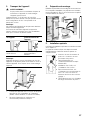
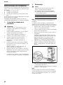
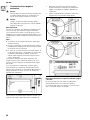
4. Installation preparation
Unpack installation materials and accessories.
To simplify installation, the packages are identified with
labels A, B and C corresponding with the manual
chapters.
5. Special installation
Special installation steps are described after chapter C.
The following symbol indicates that additional steps
need to be taken before proceeding to the next
chapter.
■ The appliance may tip over while it
is being unpacked or if the doors
are opened.
■ Sealing mat, see “Removing/
changing over the sealing mat”
■ Side-by-Side installation,
see “Side-by-Side installation”.
■ Connecting the water, see
“Preparing to connect the water”
and “Connecting the water to the
appliance”.
■ Door limitation pin, see “Adjusting
the door opening angle”.
Raise up via appliance
rear
Do not raise up from
appliance side
Minimum height
86"/2185 mm
Do not raise up the
appliance via the side
panels!

en-us
12
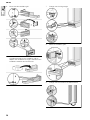
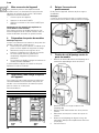
1. Attaching the anti-tip-brackets
, WARNING:
Risk of injury and damage!
Assure that there are no electrical wires or
plumbing in the area which the screws could
penetrate.
, WARNING:
Risk of injury! Always wear safety glasses and
other necessary protective devices or apparel
when installing or working with dowels.
Important note:
If a Side-by-Side set up of two appliances is envisaged,
the anti-tip brackets are needed as installation aid.
Connect the appliances before the anti-tip brackets are
fixed to the wall, see “Side-by-Side installation”.
Note:
■ 2 anti-tip-brackets are required for each appliance.
■ The supplied set contains fastening screws for
various applications. Select the fastening screws
according to the local conditions.
■ If the anti-tip brackets, and therefore the appliance,
cannot be securely attached with the supplied
fastening screws, another suitable method must be
used to attach the appliance securely.
The anti-tip-brackets (a) must overlap a minimum of
21/8” (54 mm) over the appliance to secure the
appliance.
If this minimum length cannot be observed for
structural conditions it is possible to do this by
fastening a spacer (b) behind the anti-tip angle, e.g. a
sufficiently dimensioned wood board.
The length of the plank should correspond to the width
of the installation niche!
1.
Specify the attachment points of the anti-tip-
brackets according to the chapter on “Dimensions
of the installation niche”.
2.
Attach the anti-tip-brackets completely.
Be sure screws hold tight.
Important notes for fastening with dowels and
screws:
Not recommended for use in light-weight masonry
material such as cinder block.
Not recommended for use in new concrete which has
not had time to cure.

en-us
13
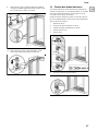
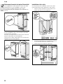
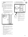
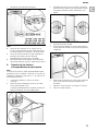
2. Attaching an alternative anti-tip
device
Important note:
If the anti-tip brackets cannot be attached securely, an
alternative anti-tip-device can be attached. However,
ensure that there is no play between the appliance and
the anti-tip-device. If possible, always screw the wooden
beam to existing studs on the rear panel of the
installation niche.
1.
Specify the attachment points of the anti-tip-
brackets according to the chapter on “Dimensions
of the installation niche”.
Note:
■ If the installation niche is deeper than the
appliance, select a beam which has a larger
cross section or attach 2 beams.
■ The beam must cover the appliance by
at least 2" (50.8 mm).
2.
Mark the installation height (lower edge of the
beam) on the rear panel of the installation niche.
3.
Select screws according to the thickness of the
wooden beam: length = min. 2.5 x beam
thickness, diameter #12 or #14.
Note:
Choose the number of screws according to the
installation niche width, thereby ensuring that the
beam can be attached securely.
4.
Depending to the subsurface:
Locate wall studs in the rear of the installation
niche and accordingly transfer their location to the
wooden beam
or fasten suitable dowel into the rear wall.
5.
Predrill the wooden beam.
6.
Attach the wooden beam to the rear panel of the
installation niche.
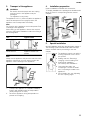
3. Attaching an edge protection
To protect the edges of the installation niche, it is
recommended to attach edge protection made of a
suitable material.
The following are special installation
steps. Instructions are provided after
chapter C.
■ Change over door hinge, see
“Changing over the door hinges”.
■ Sealing mat, see “Removing/
changing over the sealing mat”
■ Side-by-Side installation,
see “Side-by- Side installation”.
■ Connecting the water, see
“Preparing to connect the water”.

en-us
14
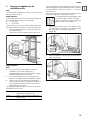
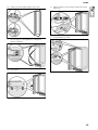
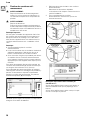
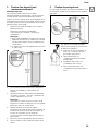
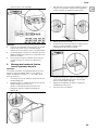
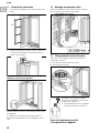
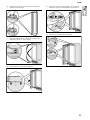
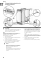
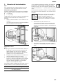
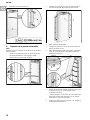
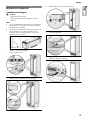
1. Pushing the appliance into the
installation niche
, CAUTION:
Caution when pushing the appliance into the
installation niche. Do not damage the water line
or power cord.
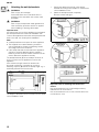
Note:
When the floor or the appliance is not leveled in
comparison to the installation niche adjust height
adjustable wheels before you move the appliance into
the installation niche.
1.
Remove the base panel.
2.
Raise the height-adjustable wheels at the back by
approx.
3
/
8
" (10 mm).
3.
Put the electric plug into the socket.
4.
Push the water line into the guard tube (a) at the
rear of the appliance.
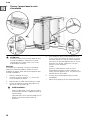
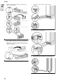
, WARNING:
Be careful, otherwise people who are helping
may be injured or the appliance may be
damaged.
The appliance may tip over while the water
line is pushing into the guard tube (a).
5.
To prevent the power cord from becoming caught,
tie a piece of string to the middle of the power
cord and feed forwards over the top of the
appliance. When pushing in the appliance, pull the
cable upwards. Take care not to pinch the power
cord
or
using adhesive tape, tape the power cord to the
floor centrally behind the appliance approx. 15"
(380 mm) away from the rear panel of the
installation niche.
6.
Carefully push the appliance into the installation
niche.
7.
Remove edge protection (if attached).

en-us
15
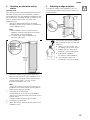
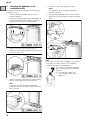
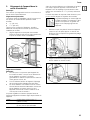
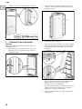
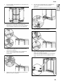
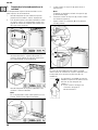
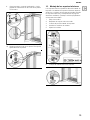
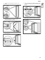
2. Aligning the appliance in the
installation niche
Note:
To ensure that the appliance functions correctly, it must
be set perfectly levelled.
Depth alignment
The positioning aid on the door have been designed for
the following total thickness of door panels:
■
3
/
4
" (19 mm)
■ 1
1
/
2
" (38 mm)
Always take account of the possible differing thickness
of the panel fronts which are to be fitted subsequently.
1.
Align the appliance with the cabinet fronts using
the positioning aid.
Place level over the positioning aid on the door.
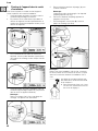
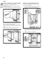
Height alignment
Note:
■ Do not twist or jam the appliance inside the
installation niche! When adjusting the
heightadjustable feet, proceed gradually: Always
alternate between left and right, etc.
■ For easier adjustment of the rear feet take the
weight off by slightly tilting the appliance forward.
■ When using a wooden beam as an alternative
antitip mechanism, turn the appliance as far as it
will go against the wooden beam. Do not bend
against the wooden beam.
The height-adjustable feet at the front and rear can all
be adjusted from the front.
The mark (a) attached at the appliance base is used as
a standard gage for height adjustment. When adjusting
the height, align this mark at a height of 1
1
/
4
" (32 mm)
above the floor.
It is very important to comply with this dimension for the
subsequent alignment of the furniture fronts.
The height adjustment gauge (b) is used
to set this height correctly. The upper
edge of the gauge must be in alignment
with the mark on the appliance.
2.
Unscrew the feet at the front of the appliance until
the mark (a) on the appliance is in alignment with
the upper edge of the height adjustment
gauge (b).
3.
Align the appliance vertically using the feet at the
back. Use a level!
Front:
with open-ended wrench
1
/
2
"
(Width across flats 13 mm)
Rear:
with
5
/
16
" (8 mm) hex nut driver via
flexible shaft.

en-us
16
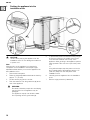
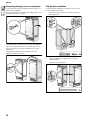
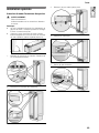
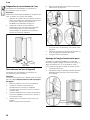
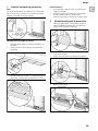
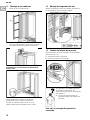
3. Attaching the appliance to the
installation niche
It is essential to attach the appliance to the top of the
installation niche.
1.
Screw the attachment plate lugs (top) to the
overhead furniture.
2.
If there is a fairly large gap above the appliance, fit
a wooden beam above the appliance, ensuring
that the wooden beam fits the gap exactly.
3.
If there is enough room on the top of the
appliance, fix the attachment plate side lugs (top)
to the side of the niche.
4.
Screw on the bars of the fastening sheets (lateral)
with the cabinet parts located next to them.
Note:
In the case of a Side-by-Side installation this
installation step is not possible. These parts have
been removed.
5.
Shorten the fitting strip (a) to fill the gap.
Note:
The appliance will be damaged if the fitting
strip (a) is too long.
6.
Press the fitting strip (a) into the cover strip (b).
7.
Attach the cover strip (b) to the attachment plate
(top).
Note:
In the case of a side-by-side installation connect both
cover rails to the bolt included in the installation
accessories for side-by-side installation.
The following are special installation
steps. Instructions are provided after
chapter C.
■ Connecting the water, see
“Connecting the water to the
appliance”.

en-us
17
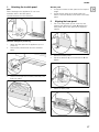
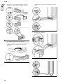
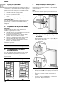
1. Attaching the toe kick panel
Note:
Risk of damage to the appliance. Do not cover
ventilation slots in the base panel.
Nominal dimensions to be observed:
Stainless steel panel (accessory)
1.
Attach the base panel to the appliance (do not
screw on).
2.
Remove the protective film from the adhesive
pads.
3.
Fit the toe kick panel to the base panel and press
firmly into place.
Wooden panel
1.
If required, shorten wooden panel to the required
length.
2.
Screw wooden panel to the base panel from
behind. There are already screw holes in the base
panel.
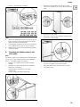
2. Aligning the base panel
1.
Put on the base panel (do not screw on) and
measure the difference in depth A between the
base panel and toe kick panel of the adjacent
cabinet.
2.
Remove the base panel.
3.
Adjust the brackets (a) to the dimensions A and
tighten.
4.
Attach the base panel.

en-us
18
3. Switching the appliance ON
To guarantee the accuracy of the following working
steps and thus the appearance of the overall kitchen
front later on, the appliance should now be operated.
1.
Open the appliance door.
2.
Press the POWER button.
3.
Press the POWER button again to shut off.
Only for appliances with a water connection:
In order to avoid the risk of damage caused by leaking
water from damage possibly caused to the water pipe
feeding the appliance, keep the shut-off valve closed.
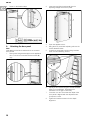
4. Preparing the door panels
Important note:
When performing any work on the door panels, always
observe the following:
■ Always screw into the best load-bearing material
of the door panel.
■ Never screw into fillers, decorative strips or
similar.
■ Select a screw length which is always shorter than
the thickness of the door panel.
■ To prevent damage, protect surfaces of the door
panels during installation.
The total weight of the door panel must not exceed the
following values:
5. Loading the appliance door
When attaching the door panels, it is recommended to
load the door storage compartments in the appliance
with weights in order to ensure that the gap width is as
precise as possible.
Recommendations:
6. Removing the installation support
part
Unscrew the positioning aid from the appliance door.
Note:
Store the positioning aids, there will be used in an
installation step later.
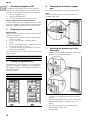
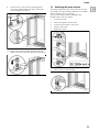
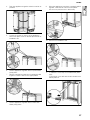
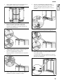
7. Attaching the adjusting rail to the
door panel
1.
Measure the distance A between the adjusting rail
and the overhead cabinet/fixtures.
2.
Loosen the 2 nuts (a) and remove the adjusting
rail (b).
3.
Mark this amount A on the rear of the door panel.
4.
Determine and mark the centerline of the door
panel.
5.
Put on the adjusting rail and align along the
marks. Mark the drill holes.
6.
Drill the holes.
18" Appliance 44 Ibs/20 kg
30" Appliance 64 Ibs/29 kg
18" Appliance 22 Ibs/10 kg
30" Appliance 44 Ibs/20 kg

en-us
19
7.
Screw on the adjusting rail tightly.
Note:
■ Attach the adjusting rail to the door panel with at
least 10 screws. One screw should be inserted
under each double threaded bolt.
■ The adjusting rail features a variety of holes for the
many different design options of door panels.
■ Always screw into the best load-bearing material
of the door panel.
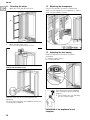
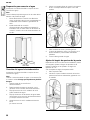
8. Attaching the fixation strips to the
door panel
Note:
The fixation strips are pre-assembled for stainless steel
doors. In this case continue with the next installation
step (“C / 9. Attaching the door panel”).
1.
Hang the door panel on the double threaded
bolt (a).
2.
Align the door panel with the double threaded
bolts (Torx screwdriver).
Re-examine the dimensions of the gap
continuously.
Use the height adjustment gauge (b).
3.
Transfer the middle drill holes along the outer
edge of the appliance door to the door panel and
mark.
4.
Remove the door panel.
5.
Using the positioning aid, mark the vertical sides
of the door panel parallel.
6.
Using a square, extend the drill hole marks which
you have just made to the vertical marks.
7.
Apply the fixation strip and mark out the holes.
8.
Pre-drill the holes.

en-us
20
9.
Screw on the fixation strips.
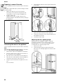
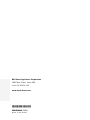
9. Attaching the door panel
Note:
Now attach the furniture handles which are screwed
from behind!
1.
Remove the fixing brackets (a) from the appliance
door. To do this, loosen the bracket screws (b)
only.
2.
Insert removed fixing brackets (a) into the
adjusting rails (b) on the door panel.
3.
Open the appliance door.
4.
Hang the door panel with adjusting rail over the
double threaded bolts.
5.
Lower door panel and push the fixing brackets
down over the fastening screws.
6.
Adjust the door panel using the double threaded
bolts (Torx screwdriver). Re-examine the
dimensions of the gap continuously.
7.
Close the door and check that the depth of the
door panel is aligned with the adjacent fronts.
If required, correct.
8.
Tighten the bracket screws to fix the depth
alignment.
La page charge ...
La page charge ...
La page charge ...
La page charge ...
La page charge ...
La page charge ...
La page charge ...
La page charge ...
La page charge ...
La page charge ...
La page charge ...
La page charge ...
La page charge ...
La page charge ...
La page charge ...
La page charge ...
La page charge ...
La page charge ...
La page charge ...
La page charge ...
La page charge ...
La page charge ...
La page charge ...
La page charge ...
La page charge ...
La page charge ...
La page charge ...
La page charge ...
La page charge ...
La page charge ...
La page charge ...
La page charge ...
La page charge ...
La page charge ...
La page charge ...
La page charge ...
La page charge ...
La page charge ...
La page charge ...
La page charge ...
La page charge ...
La page charge ...
La page charge ...
La page charge ...
La page charge ...
La page charge ...
La page charge ...
La page charge ...
La page charge ...
La page charge ...
La page charge ...
La page charge ...
La page charge ...
La page charge ...
La page charge ...
La page charge ...
La page charge ...
La page charge ...
La page charge ...
La page charge ...
La page charge ...
La page charge ...
La page charge ...
La page charge ...
-
 1
1
-
 2
2
-
 3
3
-
 4
4
-
 5
5
-
 6
6
-
 7
7
-
 8
8
-
 9
9
-
 10
10
-
 11
11
-
 12
12
-
 13
13
-
 14
14
-
 15
15
-
 16
16
-
 17
17
-
 18
18
-
 19
19
-
 20
20
-
 21
21
-
 22
22
-
 23
23
-
 24
24
-
 25
25
-
 26
26
-
 27
27
-
 28
28
-
 29
29
-
 30
30
-
 31
31
-
 32
32
-
 33
33
-
 34
34
-
 35
35
-
 36
36
-
 37
37
-
 38
38
-
 39
39
-
 40
40
-
 41
41
-
 42
42
-
 43
43
-
 44
44
-
 45
45
-
 46
46
-
 47
47
-
 48
48
-
 49
49
-
 50
50
-
 51
51
-
 52
52
-
 53
53
-
 54
54
-
 55
55
-
 56
56
-
 57
57
-
 58
58
-
 59
59
-
 60
60
-
 61
61
-
 62
62
-
 63
63
-
 64
64
-
 65
65
-
 66
66
-
 67
67
-
 68
68
-
 69
69
-
 70
70
-
 71
71
-
 72
72
-
 73
73
-
 74
74
-
 75
75
-
 76
76
-
 77
77
-
 78
78
-
 79
79
-
 80
80
-
 81
81
-
 82
82
-
 83
83
-
 84
84


Bosch B18IF800SP/01 Guide d'installation
- Catégorie
- Congélateurs
- Taper
- Guide d'installation
- Ce manuel convient également à
dans d''autres langues
Documents connexes
Autres documents
-
Bosch Benchmark B18IF900SP Guide d'installation
-
Thermador TFL18IR800 Guide d'installation
-
Gaggenau RY 492 Guide d'installation
-
-
Thermador T30BB810SS Guide d'installation
-
-
 Gaggenau USA RW414761 Guide d'installation
-
Miele KWT 16x1 Vi Le manuel du propriétaire
