
Questions?
Help is just a moment away!
Call: Home Generator Helpline
800 743-4115 M-F 8-5 CT
Home Generator System
Installation Manual
7000 & 10000 Watt Automatic

Thank you for purchasing this quality-built Briggs & Stratton home generator. We’re pleased that you’ve placed your
confidence in the Briggs & Stratton brand. When operated and maintained according to the instructions in the operator’s
manual, your home generator will provide many years of dependable service.
This manual contains safety information to make you aware of the hazards and risks associated with residential generator
systems and how to avoid them. This generator system is designed and intended only for use as an optional home standby
system that provides an alternate source of electric power and to serve loads such as heating, refrigeration systems, and
communication systems that, when stopped during any power outage, could cause discomfort or inconvenience. Save these
instructions for future reference.
This generator system requires professional installation before use. The installer should follow the instructions completely.
Where to Find Us
You never have to look far to find support and service for your generator. Consult your Yellow Pages. There are many
Briggs & Stratton authorized service dealers who provide quality service. You can also contact Technical Service by phone at
800 743-4115 between 8:00 AM and 5:00 PM CT, or click on Find a Dealer at BRIGGSandSTRATTON.COM, which provides a
list of authorized dealers.
For Future Reference
Please fill out the information below and keep with your receipt to assist in unit identification for future purchase issues.
Date of Purchase
Generator
Model Number
Model Revision
Serial Number
Engine
Model Number
Serial Number
Briggs & Stratton Power Products Group, LLC
P.O. Box 702
Milwaukee, WI 53201-0702
Copyright © 2010. All rights reserved. No part of this material
may be reproduced or transmitted in any form without the express
written permission of Briggs & Stratton Power Products Group, LLC.

3
Table of Contents
Important Safety Instructions........................4
Installation ....................................7
Installing Dealer/Contractor Responsibilities ........................7
Delivery Inspection............................................7
Shipment Contents............................................7
The Gaseous Fuel System .....................................10
Fuel Pipe Sizing .............................................12
Fuel Consumption ...........................................12
System Connectors ..........................................13
Grounding the Generator ......................................14
Fault Detection System .......................................15
System Control Panel.........................................15
Final Installation Considerations ................................16
Engine Adjustment...........................................17
Test Shutdown(s) Procedure ...................................17
Fuel Conversion .............................................19
7000 Watt Schematic Diagram .................................20
7000 Watt Wiring Diagram ....................................21
10000 Watt Schematic Diagram ................................22
10000 Watt Wiring Diagram ...................................23
Controls ..................................... 24
Operation .................................... 24
Automatic Operation Sequence .................................24
Setting Exercise Timer ........................................24
Installation Inspection ........................................24

4
Important Safety Instructions
SAVE THESE INSTRUCTIONS - This manual contains
important instructions that should be followed during
installation and maintenance of the generator and batteries.
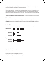
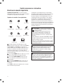
Safety Symbols and Meanings
The safety alert symbol indicates a potential personal
injury hazard. A signal word (DANGER, WARNING, or
CAUTION) is used with the alert symbol to designate a
degree or level of hazard seriousness. A safety symbol
may be used to represent the type of hazard. The signal
word NOTICE is used to address practices not related to
personal injury.
DANGER indicates a hazard which, if not avoided, will
result in death or serious injury.
WARNING indicates a hazard which, if not avoided, could
result in death or serious injury.
CAUTION indicates a hazard which, if not avoided, could
result in minor or moderate injury.
NOTICE addresses practices not related to personal injury.
The manufacturer cannot possibly anticipate every possible
circumstance that might involve a hazard. The warnings in
this manual, and the tags and decals affixed to the unit are,
therefore, not all-inclusive. If you use a procedure, work
method or operating technique that the manufacturer does
not specifically recommend, you must satisfy yourself that
it is safe for you and others. You must also make sure that
the procedure, work method or operating technique that you
choose does not render the generator system unsafe.
Explosion
Fire
Electrical Shock
Rotating Parts
Hot Surface
Toxic Fumes
Chemical BurnExplosive PressureAuto Start
Lift Hazard
Read Manual
Save These Instructions
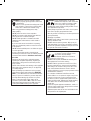
WARNING Running engine gives off carbon monoxide,
an odorless, colorless, poison gas.
Breathing carbon monoxide could result in death,
serious injury, headache, fatigue, dizziness,
vomiting, confusion, seizures, nausea or fainting.
Operate this product ONLY outdoors.•
Install a battery operated carbon monoxide alarm near •
the bedrooms.
Keep exhaust gas from entering a confined area through •
windows, doors, ventilation intakes, or other openings.
WARNING Storage batteries give off explosive
hydrogen gas during recharging.
Slightest spark will ignite hydrogen
and cause explosion, resulting
in death, serious injury and/or
property damage.
Battery electrolyte fluid contains acid and is
extremely caustic.
Contact with battery contents could cause severe
chemical burns.
A battery presents a risk of electrical shock and high short
circuit current.
DO NOT dispose of battery in a fire. Recycle battery.•
DO NOT allow any open flame, spark, heat, or lit cigarette •
during and for several minutes after charging a battery.
DO NOT open or mutilate the battery.•
Wear protective goggles, rubber apron, rubber boots and •
rubber gloves.
Remove watches, rings, or other metal objects.•
Use tools having insulated handles.•
WARNING The engine exhaust from this product
contains chemicals known to the State of California to
cause cancer, birth defects, or other reproductive harm.
WARNING Certain components in this product and
related accessories contain chemicals known to the State
of California to cause cancer, birth defects, or other
reproductive harm. Wash hands after handling.

5
WARNING Generator produces hazardous voltage.
Failure to properly ground generator could result
in electrocution.
Failure to isolate generator from utility power could
result in death or serious injury to electric utility
workers due to backfeed of electrical energy.
When using generator for backup power, notify •
utility company.
DO NOT touch bare wires or bare receptacles.•
DO NOT use generator with electrical cords which are •
worn, frayed, bare or otherwise damaged.
DO NOT handle generator or electrical cords while •
standing in water, while barefoot, or while hands or
feet are wet.
If you must work around a unit while it is operating, •
stand on an insulated dry surface to reduce the risk of
a shock hazard.
DO NOT allow unqualified persons or children to operate •
or service generator.
In case of an accident caused by electrical shock, •
immediately shut down the source of electrical power and
contact the local authorities. Avoid direct contact with
the victim.
Despite the safe design of the residential generator, •
operating this equipment imprudently, neglecting its
maintenance or being careless could cause possible
injury or death.
Remain alert at all times while working on this equipment. •
Never work on the equipment when you are physically
or mentally fatigued.
Before performing any maintenance on the generator, •
disconnect the battery cable indicated by a NEGATIVE,
NEG or (-) first. When finished, reconnect that cable last.
After your system is installed, the generator may crank •
and start without warning any time there is a power
failure. To prevent possible injury, always set the
generator’s system switch to OFF, remove the service
disconnect from the disconnect box AND remove the
15 Amp fuse BEFORE working on the equipment.
WARNING Propane and Natural Gas are extremely
flammable and explosive, which could cause
burns, fire or explosion resulting in death,
serious injury and/or property damage.
Install the fuel supply system according to NFPA 37 and •
other applicable fuel-gas codes.
Before placing the generator into service, the fuel system •
lines must be properly purged and leak tested.
After the generator is installed, you should inspect the fuel •
system periodically.
NO leakage is permitted.•
DO NOT operate engine if smell of fuel is present or other •
explosive conditions exist.
DO NOT smoke around the generator. Wipe up any oil •
spills immediately. Ensure that no combustible materials
are left in the generator compartment. Keep the area near
the generator clean and free of debris.
WARNING
Exhaust heat/gases could ignite combustibles
or structures resulting in death, serious
injury and/or property damage.
Contact with muffler area could cause
burns resulting in serious injury.
DO NOT touch hot parts and AVOID hot exhaust gases.•
Allow equipment to cool before touching.•
DO NOT install the generator closer than 5 feet (1.5m) •
from any combustibles or structures with combustible
walls having a fire resistance rating of less than 1 hour.
Keep at least minimum distances shown in • General
Location Guidelines to insure for proper generator cooling
and maintenance clearances.
It is a violation of California Public Resource Code, •
Section 4442, to use or operate the engine on any forest-
covered, brush-covered, or grass-covered land unless
the exhaust system is equipped with a spark arrester, as
defined in Section 4442, maintained in effective working
order. Other states or federal jurisdictions may have
similar laws.
Contact the original equipment manufacturer, retailer, or
dealer to obtain a spark arrester designed for the exhaust
system installed on this engine.
Replacement parts must be the same and installed in the •
same position as the original parts.

6
WARNING Hazardous Voltage - Contact with power
lines could cause electric shock or burns,
resulting in death or serious injury.
Lifting Hazard / Heavy Object - Could result
in serious injury.
If lifting or hoisting equipment is used, DO NOT contact •
any power lines.
DO NOT lift or move generator without assistance.•
DO NOT lift unit by roof as damage to generator •
will occur.
WARNING Starter and other rotating parts could
entangle hands, hair, clothing, or accessories
resulting in serious injury.
NEVER operate generator without protective housings, •
covers, or guards in place.
DO NOT wear loose clothing, jewelry or anything that •
could be caught in the starter or other rotating parts.
Tie up long hair and remove jewelry.•
Before servicing, remove 15 Amp fuse from control panel •
and disconnect Negative (NEG or -) battery cable.
CAUTION Installing the 15A fuse could cause the
engine to start at any time without warning
resulting in minor or moderate injury.
Observe that the 15 Amp fuse has been removed from the •
control panel for shipping.
DO NOT install this fuse until all plumbing and wiring has •
been completed and inspected.
CAUTION Excessively high operating speeds could
result in minor injury and/or equipment damage.
Excessively low speeds impose a heavy load on generator.
DO NOT tamper with governed speed. Generator supplies •
correct rated frequency and voltage when running at
governed speed.
DO NOT modify generator in any way.•
NOTICE Improper treatment of generator could damage it
and shorten its life.
Use generator only for intended uses.•
If you have questions about intended use, contact your •
authorized dealer.
Operate generator only on level surfaces.•
Adequate, unobstructed flow of cooling and ventilating air •
is critical to correct generator operation.
The access panels/doors must be installed whenever the •
unit is running.
DO NOT expose generator to excessive moisture, dust, •
dirt, or corrosive vapors.
Remain alert at all times while working on this equipment. •
Never work on the equipment when you are physically
or mentally fatigued.
DO NOT start engine with air cleaner or air cleaner •
cover removed.
DO NOT insert any objects through cooling slots.•
DO NOT use the generator or any of its parts as a step. •
Stepping on the unit could cause stress and break parts.
This may result in dangerous operating conditions from
leaking exhaust gases, fuel leakage, oil leakage, etc.
If connected devices overheat, turn them off and •
disconnect them from generator.
Shut off generator if •
- electrical output is lost;
- equipment sparks, smokes, or emits flames;
- unit vibrates excessively.
NOTICE Exceeding generators wattage/amperage
capacity could damage generator and/or electrical devices
connected to it.
Start generator and let engine stabilize before connecting •
electrical loads.

7
Installation
Equipment Description
This product is intended for use as an optional residential
generator system which provides an alternate source
of electric power and to serve loads such as heating,
refrigeration systems, and communication systems that,
when stopped during any power outage, could cause
discomfort or inconvenience. This product does not qualify
for emergency standby as defined by NFPA 70 (NEC).
Every effort has been made to ensure that information in this
manual is accurate and current. However, we reserve the
right to change, alter, or otherwise improve the product and
this document at any time without prior notice.
Only current licensed electrical and plumbing
professionals should attempt home generator system
installations. Installations must strictly comply with all
applicable codes, industry standards and regulations.
Home Owner Responsibilities
• Readandfollowtheinstructionsgiveninthe
operator’s manual.
• Followaregularscheduleinmaintaining,caringfor
and using your home generator, as specified in the
operator’s manual.
If you have questions about intended use, ask your installer
or dealer or call 800 743-4115 between 8:00 AM and
5:00 PM CT.
Installing Dealer/Contractor Responsibilities
• Readandobservethesafetyrules.
• InstallonlyanULapprovedtransferswitchthatis
compatible with the generator.
• Readandfollowtheinstructionsgiveninthis
installation and start-up manual.
If operating the generator below 40°F (5°C), it is HIGHLY
RECOMMENDED that a battery warmer be installed. This
item is available at your local servicing dealer. It is also
HIGHLY RECOMMENDED that the higher capacity colder
climate battery be installed. See Battery Specification table
under Final Installation Considerations.
Unpacking Precautions
The unit is shipped bolted to its mounting pad, ready
for installation. Avoid damage from dropping, bumping,
collision, etc. Store and unpack carton with the proper side
up, as noted on the shipping carton.
Delivery Inspection
After removing the carton, carefully inspect the home
generator for any damage that may have occurred
during shipment.
If loss or damage is noted at time of delivery, have the
person(s) making delivery note all damage on the freight
bill and affix his signature under the consignor’s memo of
loss or damage. If loss or damage is noted after delivery,
separate the damaged materials and contact the carrier
for claim procedures. Missing or damaged parts are
not warranted.
Shipment Contents
The generator is supplied with:
• Pre-attachedmountingpad
• Fully-servicedoil/lubricatingsystem
• Flexiblefuelhook-uphose
• Installationandstart-upmanual
• Operator’smanual
• Engineoperator’smanual
• Installationchecklist
• Accessdoorkeys
• Spare15AmpATO-typefuse
• Two-pincontrolpanelconnector
• Ten-pincontrolpanelconnector
• Oildraintray
• Touchuppaint
• Fuelconversionkit(7kWonly)
• Roofhardware
Not supplied:
• Startingbattery(seepage16)
• Connectingwireandconduit
• Fuelsupplyvalves/plumbing
• Crane,liftingstraps,chainsorcables
• Holepunchesfor16gasteel
• Torquescrewdriver,5to50inch-poundrange
• Voltage/frequencymeter
• Variousspecialtytools/eqipment

8
Generator Location
Before installing the generator, consult with the homeowner
and convey the following guidelines, which may affect the
desired installation location.
Install generator outdoors in an area which will not
accumulate deadly exhaust gas. DO NOT install generator
where exhaust gas could accumulate and enter inside or be
drawn into a potentially occupied building. Ensure exhaust
gas is kept away from windows, doors, ventilation intakes
or other openings that can allow exhaust gas to collect in a
confined area. Prevailing winds and air currents should be
taken into consideration when positioning generator.
General Location Guidelines
• InstalltheunitoutdoorsONLY.
• Placetheunitinapreparedlocationthatisflatandhas
provisions for water drainage.
• Installtheunitinalocationwheresumppump
discharge, rain gutter down spouts, roof run-off,
landscape irrigation, or water sprinklers will not flood
the unit or spray the enclosure and enter any air inlet
our outlet openings.
• Installtheunitwhereitwillnotaffectorobstruct
any services (including covered, concealed and
underground), such as telephone, electric, fuel,
irrigation, air conditioning, and so forth.
• Installtheunitwhereairinletandoutletopeningswill
not become obstructed by leaves, grass, snow, etc. If
prevailing winds will cause blowing or drifting, you may
need to construct a windbreak to protect the unit.
• Installthegeneratorascloseaspossibletothetransfer
switch and fuel supply to reduce the length of wiring,
conduit, and piping.
Laws or local codes may regulate the distance to the
fuel supply.
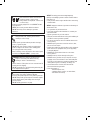
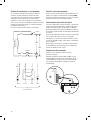
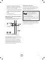
The minimum clearances from aerial view of generator (B)
to combustible (D), and non-combustible (A) materials is
shown below.
• Thesedistancesareprovidedtogivegeneratorlocation
guidance relative ONLY to combustibles, generator
cooling, and maintenance.
• Theminimumdistancesinthefigureareasshown.
All four sides of the generator cannot be enclosed
or restricted, even if the minimum distances are
maintained. DO NOT connect (A) and/or (D) to (E)
• Aroofcannotbeused.
• Exhaust(C) must not be allowed to accumulate.
A Non-Combustible material with Fire Resistant Rating of
1 hour or greater
B Home Standby Generator
C Engine Exhaust
D Combustible Material or Structure with a Fire
Resistance Rating of less than 1 hour.
E Any structure or material. DO NOT connect (A) and/or
(D) to (E).
A
B
E
D
E
C
3’
(1m)
5’ (1.5m)
5’ (1.5m)
5’ (1.5m)
5’ (1.5m)
3’
(1m)
3’
(1m)
WARNING Exhaust heat/gases could ignite
combustibles or structures resulting in death,
serious injury and/or property damage.
DO NOT install the generator closer than 5 feet (1.5m) •
from any combustibles or structures with combustible
walls having a fire resistance rating of less than 1 hour.
WARNING Running engine gives off carbon monoxide,
an odorless, colorless, poison gas.
Breathing carbon monoxide could result in death,
serious injury, headache, fatigue, dizziness,
vomiting, confusion, seizures, nausea or fainting.
Operate this product ONLY outdoors.•
Install a battery operated carbon monoxide alarm near •
the bedrooms.
Keep exhaust gas from entering a confined area through •
windows, doors, ventilation intakes, or other openings.

9
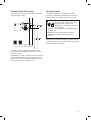
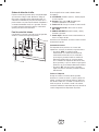
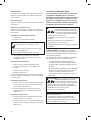
Electrical and Fuel Inlet Locations
The 3/4 inch N.P.T. fuel inlet connector (A) and electrical
inlet location (B) is shown:
The home generator is shipped already attached to its
mounting pad. Unless mandated by local code, a concrete
slab is not required.
If mandated by local code, construct a concrete slab at least
3 inches thick and 6 inches longer and wider than the unit.
Attach unit to slab with 1/4” diameter (minimum) masonry
anchor bolts long enough to retain the unit.
Lifting the Generator
The generator weighs more than 350 pounds (159 kg).
Proper tools, equipment and qualified personnel should be
used in all phases of handling and moving the generator.
Lifting pockets are provided at each corner between the base
of the generator and its mounting pad. Retouch any chipped
paint with supplied touch-up paint.
B
A
WARNING Hazardous Voltage - Contact with power
lines could cause electric shock or burns,
resulting in death or serious injury.
Lifting Hazard / Heavy Object - Could result
in serious injury.
If lifting or hoisting equipment is used, DO NOT contact •
any power lines.
DO NOT lift or move generator without assistance.•
DO NOT lift unit by roof as damage to generator •
will occur.

10
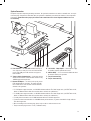
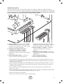
Access Ports
The generator is equipped with several access openings and
a removable roof to permit simple oil and filter servicing.
To remove roof:
Remove the four screws and lift off. Replace roof in
reverse order.
To remove access cover:
Remove the two screws, tilt cover out, and lift cover off
panel. Replace cover in reverse order.
To remove side panel (if necessary):
1. Remove roof.
2. Remove screw(s) attaching side panel.
3. Pull panel outward (away) from unit while pulling panel
upward and out of base.
To install side panel:
1. Guide bottom of side into base.
2. Push panel until it is flush with sides.
3. Replace panel screw(s).
4. Replace roof and screws.
Each generator is suppied with a set of identical keys. These
keys fit the locks that secure the access door.
To open access door:
1. Insert key into lock of access door handle and turn key
one quarter turn counterclockwise.
2. Grasp door’s handle and turn one quarter turn
counterclockwise to open. Remove key.
To close access door:
1. Close door and turn doors handle one quarter
turn clockwise.
2. Insert key into lock of door handle and turn key one
quarter turn clockwise. Remove key.
The Gaseous Fuel System
The information below is provided to assist gaseous fuel
system technicians in planning installations. In no way
should this information be interpreted to conflict with
applicable fuel gas codes. Consult with your local fuel
supplier or Fire Marshall if questions or problems arise.
TO THE INSTALLER: Consult with the generator owner(s)
and convey any technical considerations that might
affect their installation plans before applying these
general guidelines.
The following general rules apply to gaseous fuel
system piping:
• Thepipingshouldbeofamaterialthatconformsto
federal and local codes, rigidly mounted and protected
against vibration.
• Pipingshouldbeprotectedfromphysicaldamage
where it passes through flower beds, shrub beds, and
other cultivated areas where damage could occur.
WARNING Contact with muffler area could cause burns
resulting in serious injury.
DO NOT touch hot parts and AVOID hot exhaust gases.•
Allow equipment to cool before touching.•
WARNING Propane
and Natural Gas are extremely
flammable and explosive, which could cause
burns, fire or explosion resulting in death,
serious injury and/or property damage.
LP gas is heavier than air and will settle in low areas.•
Natural gas is lighter than air and will collect in high areas.•
The slightest spark could ignite these fuels and cause •
an explosion.
DO NOT light a cigarette or smoke.•
NOTICE The supplied flexible gaseous pipe is not to be
installed underground or in contact with the ground.
The entire flexible gaseous pipe must be visible for •
periodic inspection and must not be concealed within nor
contact nor run through any wall, floor, or partition.
WARNING
Propane and Natural Gas are extremely
flammable and explosive, which could cause
burns, fire or explosion resulting in death,
serious injury and/or property damage.
Before placing the generator into service, the fuel system •
lines must be properly purged and leak tested.
No leakage is permitted.•

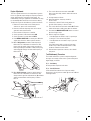
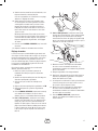
11
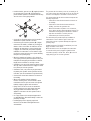
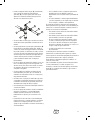
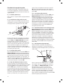
• Installtheflexible,gaseoushose(B) (supplied) between
the generator fuel inlet port (A) and rigid piping to
prevent thermal expansion or contraction from causing
excessive stress on the piping material.
• Aunion(C) or flanged connection shall be provided
downstream to permit removal of controls.
• Amanometerportshouldbeprovided(D). A digital
manometer, P/N 19495, is available at your Briggs &
Stratton service center. When the initial test runs are
completed, the manometer is removed and the port
is plugged. The manometer port permits temporary
installation of a manometer to ensure that the engine
receives the correct fuel pressure to operate efficiently
throughout its operating range.
• Wheretheformationofhydratesoriceisknownto
occur, piping should be protected against freezing. The
termination of hard piping should include a sediment
trap (E) where condensate is not likely to freeze.
• Aminimumofoneaccessible,approvedmanualshutoff
valve (F) shall be installed in the fuel supply line within
6 ft (180 cm) of the home generator.
• Aminimum10ft.(3m)sectionofgaspipebetween
the primary fuel regulator and the generator fuel inlet
connection (acts as accumulator for high block loads).
• Amanualfuelshut-offvalvelocatedintheinteriorof
the building.
• Wherelocalconditionsincludeearthquake,
tornado, unstable ground, or flood hazards, special
consideration shall be given to increase strength and
flexibility of piping supports and connections.
• Pipingmustbeofthecorrectsizetomaintainthe
required supply pressures and volume flow under
varying generator load conditions with all gas
appliances connected to the fuel system turned on
and operating.
• Useapipesealantorjointcompoundapprovedfor
use with NG/LPG on all threaded fittings to reduce the
possibility of leakage.
• Installedpipingmustbeproperlypurgedand
leak tested, in accordance with applicable codes
and standards.
The generator has been factory set to run on natural gas. If
you need to change from natural gas to LP gas, the unit will
need to be reconfigured, as described in Fuel Conversion.
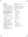
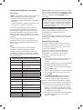
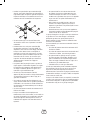
It is recommended that the fuel connection incorporate the
following components:
• Amanualfuelshut-offvalvelocatedintheinteriorof
the building.
• Amanualfuelshut-offvalvelocatedoutsidethe
building, just before the generator unit.
• Wheretheformationofhydratesoriceisknownto
occur, piping should be protected against freezing. The
termination of hard piping should include a sediment
trap where condensate is not likely to freeze.
• Amanometerportshouldbeprovided.
The manometer port permits temporary installation of
a manometer to ensure that the engine receives the
correct fuel pressure to operate efficiently throughout its
operating range.
A digital manometer, P/N 19495, is available at your local
Briggs & Stratton service center.
When the initial test runs are completed, the manometer
is removed and the port is plugged. A typical final fuel
connection assembly is shown here, where (A) is the fuel
supply and (F) goes to the home generator.
B
C
D
F
E
A

12
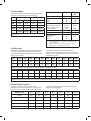
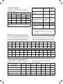
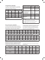
Fuel Consumption
Estimated fuel supply requirements at half and full load for
natural gas and LP vapor fuels are shown below.
Natural Gas LP Vapor
1/2 Load Full Load 1/2 Load Full Load
7 kW 80 C 137 C 33 C 56 C
80,000 B 137,000 B 82,500 B 140,000 B
10 kW 84 C 162 C 35 C 65 C
84,000 B 162,000 B 86,375 B 163,625 B
C = Cubic feet per hour
B = BTU’s per hour
Physical Properties LP Vapor Natural
Gas
Normal Atmospheric State Gas Gas
Boiling Point (in °F):
Initial
End
-44
-44
-259
-259
Heating Value:
BTU per gallon (Net LHV*)
BTU per gallon (gross**)
Cubic feet (gas)
83,340
91,547
2,500
63,310
1,000
Density*** 36.39 57.75
Weight† 4.24 2.65
Octane Number:
Research
Motor
110+
97
110+
* LHV (Low Heat Value) is the more realistic rating.
** Gross heat value does not consider heat lost in the form of water
during combustion.
*** Density is given in “Cubic Feet of Gas per Gallon of Liquid”.
† Weight is given in “Pounds per Gallon of Liquid”.
Withdrawal Rate 32° F 20° F 10° F 0° F -10° F -30° F -40° F
50 CFH 115 115 115 250 250 400 600
100 CFH 250 250 250 400 500 1000 1500
150 CFH 300 400 500 500 1000 1500 2500
200 CFH 400 500 750 1000 1200 2000 2500
300 CFH 750 1000 1500 2000 2500 4000 5000
NPT 10ft 15ft 20ft 30ft 40ft 50ft 60ft 70ft 80ft 90ft 100ft
3/4” 346 293 240 192 163 145 132 120 113 106 99
1” 653 549 446 360 307 274 250 230 211 197 187
Natural Gas Pipe Size - Gas Flow chart, in cubic feet per hour, specific gravity=0.65
NPT 10ft 15ft 20ft 30ft 40ft 50ft 60ft 70ft 80ft 90ft 100ft
3/4” 277 192 158 126 107 95 87 79 74 69 65
1” 428 360 293 236 202 180 164 151 139 129 123
Liquid Propane (LP) Gas Pipe Size - Gas Flow chart, in cubic feet per hour, specific gravity=1.50
Fuel Pipe Sizing
The tables below provide the maximum capacity of pipe in
cubic feet of gas per hour for gas pressures of 0.5 psi or
less and a pressure drop of 0.3 in. water column. Specific
gravity of gas is shown.
Listed values compensate for a nominal amount of
restriction from bends, fittings, etc. If an unusual number of
fittings, bends, or other restrictions are used, please refer to
federal and local codes.
Required Propane Tank Size
The required size of the propane tank at various
temperatures when kept at least half full is shown below
in the chart. Given the gas withdrawal rate and the lowest
average winter temperature, an installer can specify the
required LP storage tank size.

13
• For7kWpoweroutputconnection,use#10AWGminimum300volt75°C-90°Ccopperwire,(ref.NECTable310.16,
100 ft. Use National Electric Code for correction factors and wire size calculations.)
• For10kWpoweroutputconnection,use#8AWGminimum300volt75°C-90°Ccopperwire,(ref.NECTable310.16,
100 ft. Use National Electric Code for correction factors and wire size calculations.)
• ForUtilityCircuitconnectionuse#14AWGminimum300volt75°C-90°Ccopperwire
• Fortransferswitchcommunicationuse#18AWGtwistedpairconductors,nogreaterthan200ftinlength,300volt
75°C-90°C copper wire
• Whenconnectingtotheconnectorplugs,fastenonlyonewiretoeachconnectorscrew.
• Torqueconnectorplugscrewsto7in-lb(7.9Newtonmeter).
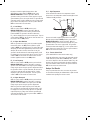
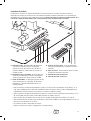
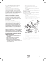
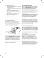
System Connectors
Except for the power output and grounding connectors, all signal wire connections are made to removable two- or ten-pin
connector plugs. Compare this illustration with your generator to familiarize yourself with the location of these important
connections. Count down to the proper pin location on the control board since visual alignment with the decal can
be misleading:
A - Fault Contacts — Use NO, COM and NC to hook up a
siren, light, etc. to alert you in case of a fault. Contacts
reverse state (NO goes to NC and vice versa) upon a
fault condition.
B - Transfer Switch Communication — Connect to transfer
switch control board for communication interface using
18AWG copper twisted pair wire.
C - Remote LED Output — Use this to hook up the remote
LED supplied with the generator. The remote LED will
turn on and off in a series of blinks if certain faults are
detected in the generator.
D - +12 Volt DC, .5 Amp Output — Internal power supply
for installer supplied, optional accessories.
E - 240 Volt Utility — Use to connect the 240V leads from
the transfer switch to the generator.
F - Ten-pin Connector Plug
G - Two-pin Connector Plug
B
A C D E F
G

14
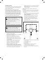
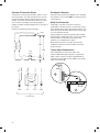
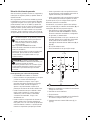
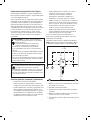
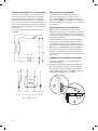
Generator AC Connection System
A single-phase, three-wire AC connection system is used in
the home generator. The stator assembly consists of a pair
of stationary windings with two leads brought out of each
winding. The junction of leads 22 and 33 forms the neutral
lead, as shown schematically and as wiring diagram. A
complete schematic and wiring diagram can be found later in
this manual.
Neutral is not bonded to ground at generator.
Grounding the Generator
Ground the home generator per applicable codes, standards,
and regulations. The generator GND lug is located inside the
control panel box.
Utility Circuit Connection
“240V Utility” leads must be routed in conduit. The
“240V Utility” leads deliver power to the generator’s circuit
board, optional battery warmer and optional oil warmer. This
power also charges the battery. When power on these leads
is lost, the generator will start.
Using provided 2 pin connector plug and installer-supplied
minimum 300V, 14 AWG copper wire, connect each control
circuit terminal in the generator to the two-amp fuse
terminals in the automatic transfer switch.
When making connections, obey wire type and torque
specifications printed on the circuit breaker and neutral/
ground connector.
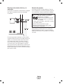
Transfer Switch Communication
(Units with ACCM II or later transfer switch only)
Using#18AWGtwistedpairconductors,nogreaterthan
200 ft in length, connect Tx Rx and Tx Rx GND from the
generator control panel (A) to T/R and GND on the transfer
switch control board (B).
33
240V
11
22
44
120V
120V
1122 33 44 0
Neutral
Power Winding
Circuit
Breaker
Ground
To Transfer Switch
Line 1
Neutral
Line 2
Circuit
Breaker
B
A

15
Fault Detection System
The generator may have to run for long periods of time with
no operator present. For that reason, the system is equipped
with sensors that automatically shut down the generator
in the event of potentially damaging conditions, such as
low oil pressure, high temperature, over speed, and other
conditions. Refer to Fault Detection System in the operator’s
manual for more detailed information.
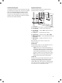
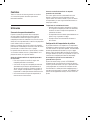
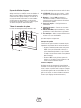
System Control Panel
The home generator control panel, located inside the
generator housing, is shown below.
Brief descriptions of the controls used during installation are:
A – SET EXERCISE — Used to set the exercise cycle.
B - Circuit Breaker — Must be ON to supply power to the
transfer switch.
C - 15 Amp Fuse —- Protects DC control circuits.
D - System Switch — Switches modes to OFF or AUTO.
E - MANUAL OVER-RIDE — Used to manually start and stop
the generator.
F - Digital Display — Displays running time in hours or
fault codes.
More information may be found in Controls in the
operator’s manual.
System Switch
This two-position switch is the most important control on
the home generator and is used as follows:
• “AUTO” position is the normal operating position. If
a utility power outage is sensed, the system will start
the generator. When utility power is restored, lets the
engine stabilize internal temperatures, shuts off the
generator, and waits for the next utility power outage.
• “OFF” position turns off running generator, prevents
unit from starting and resets any detected faults.
15 Amp Fuse
Protects the home generator DC control circuits. If the fuse
has ‘blown’ (melted open) or was removed, the engine
cannot crank or start. Replace the fuse using only an
identical ATO 15A fuse. One spare fuse is supplied with the
unit. If fuse was blown or removed, you will need to reset
the exercise timer (see Setting Exercise Timer).
B
A
C E FD

16
Final Installation Considerations
Engine Oil
The engine is shipped from the factory pre-run and filled
with synthetic oil (API SJ/CF 5W-30). This allows for system
operation in a wide range of temperature and climate conditions.
Before starting the engine, check oil level and ensure that engine
is serviced as described in the engine operator’s manual.
The use of synthetic oil does not alter the required oil change
intervals described in the engine operator’s manual.
Battery
The installer must supply and install a valve-regulated
rechargeable 12 volt starting battery. The starting battery
MUST conform to the specifications shown in these charts.
It is also HIGHLY RECOMMENDED to use a higher capacity
battery in colder climates.
Battery Specifications (Colder Climate)
Volts 12 Volt DC
Amps (MIN) 600 CCA (cold cranking amps)
Type AGM (Absorbent glass mat)
Terminal Hardware M8
Dimensions (MAX):
Width 5.43 inches (138mm)
Length 9.02 inches (229mm)
Height 8.19 inches (208mm)
Battery Specifications (Warmer Climate)
Volts 12 Volt DC
Amps (MIN) 350 CCA (cold cranking amps)
Type AGM (Absorbent glass mat)
Terminal Hardware M8
Dimensions (MAX):
Width 5.325 inches (135mm)
Length 7.875 inches (200mm)
Height 6.875 inches (175mm)
Install the battery as described in Servicing the Battery in
the Maintenance section of the operator’s manual. Always
make sure the NEGATIVE cable is connected last and that the
red POSITIVE terminal insulator is fully in place.
Fuel Supply System
Ensure that all fuel pipe connections are tight, secure and
without leaks.
Ensure that all gas line shutoff valves are OPEN and that
adequate fuel pressure is available whenever automatic
operation is desired.
Initial Start-up (No Load)
The unit has been set-up for NG operation at the factory.
Fuel conversion, if needed, must be completed prior to
performing these steps. See Fuel Conversion later in
this section.
Before operating the home generator or placing it into
service, inspect the entire installation carefully. Then begin
testing the system without any electrical loads connected,
as follows:
1. Remove four screws that secure control panel to
enclosure to expose unit’s circuit breaker.
2. Connect an accurate frequency meter to line side of
generator’s main circuit breaker.
3. Set generator’s main circuit breaker to ON
(closed) position.
4. Install 15 Amp fuse in control panel.
5. Set generator’s system switch to AUTO.
6. Push and hold MANUAL OVER-RIDE button on control
panel for about six seconds. Engine will start.
When the generator is started for the very first time, it
will require that air in the gaseous fuel lines be purged.
This may take a few minutes.
7. Listen for unusual noises, vibration or other indications
of abnormal operation. Check for oil leaks while
engine runs.
8. Let engine warm up for about five minutes to allow
internal temperatures to stabilize.
9. Check generator output at load side of circuit breaker.
Voltage should be between 239 - 262 Volts, frequency
should be between 62.0 - 62.5 Hz.
If either parameter is outside these ranges, perform
Engine Adjustment described later in this section.
10. Check generator output between one generator
connection lug and neutral lug, then between other
generator connection lug and neutral lug. In both cases,
voltage reading should be between 119 - 131 Volts.
DO NOT proceed until you are certain that generator AC
voltage and frequency are correct and within the stated
limits. To obtain the proper generator frequency, see
Engine Adjustment.
11. Push and hold MANUAL OVER-RIDE button on control
panel again until engine stops.
12. Reinstall control panel into enclosure.
NOTICE Any attempt to crank or start the engine before
it has been properly serviced with the recommended oil
will result in equipment failure.
Refer to • Maintenance in the operator’s manual and engine
manual for oil fill information.
Damage to equipment resulting from failure to follow this •
instruction will void engine and generator warranty.
WARNING Battery posts, terminals and related
accessories contain lead and lead compounds, chemicals
known to the State of California to cause cancer and
reproductive harm. Wash hands after handling.

17
Engine Adjustment
There are regional variances in the composition of gaseous
fuel. If the generator output voltage or frequency measured
during Initial Start-Up is outside the listed ranges, the
combustibility of the gas supplied at the installation site may
be substantially different from the fuel used at the factory.
To adjust the engine for this difference, proceed as follows.
1. Remove four screws that secure control panel to
enclosure to expose unit’s circuit breaker.
2. Connect an accurate frequency meter to line side of
generator’s main circuit breaker.
3. Ensure that the 15 Amp fuse is installed.
4. Set the generator’s main circuit breaker ON.
5. Set the generator’s system switch to AUTO.
6. Push MANUAL OVER-RIDE on control panel. When the
engine starts, allow it to warm up for five minutes.
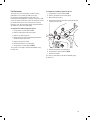
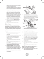
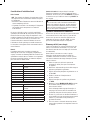
7A. For a 7 kW generator, normal no load frequency is
62.0 to 62.5 Hz. If adjustment is needed at no load,
remove unit side panels. Using needle nose pliers or
B&Stangbendingtool#19229or19480,bendspring
anchor tang (A) slowly up or down until frequency is
62.0 to 62.5 Hz.
7B. For a 10 kW generator, normal no load frequency is
62.0 to 62.5 Hz. If adjustment is needed at no load,
slowly rotate the governor adjustment nut (B) clockwise
and/or counterclockwise until frequency is 62.0 to
62.5 Hz.
8. Turn service disconnect to transfer switch OFF.
After a short time delay, transfer switch will connect
to generator.
9. Load generator to full load.
10. After load stabilizes, frequency should be
above 57.0 Hz.
11. If frequency is below 57.0 Hz, slowly adjust the
governor until frequency is above 57.0 Hz
12. Turn service disconnect to transfer switch ON. Transfer
switch will connect to utility power after five minutes.
13. Push and hold MANUAL OVER-RIDE button on control
panel until engine stops.
14. After the engine has stopped:
•Ifanadjustmentwasmadeinstep11,repeatsteps
2 through 7. Then reinstall side panels.
•Ifanadjustmentwasnotmadeinstep11,proceed
to step 15.
If no load frequency falls out of the no load range
shown in step 7 after full load adjustment is made,
contact an authorized service center.
15. Reinstall control panel into enclosure, then reinstall
side panels.
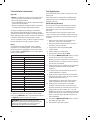
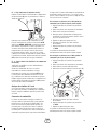
Test Shutdown(s) Procedure
The installer will test the system to verify that diagnostic
messages are correctly shown on the system control panel
digital display, as follows:
FC_1 - Low Battery
No test procedure required for this fault.
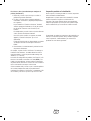
FC_2 - Low Oil Pressure:
Locatewire#85connectedtotheoilpressureswitch.
Shown here is the oil pressure switch (C) for both 7 kW and
10 kW generators:
A
C
B

18
Connect an installer-supplied jumper wire to wire
#85.WiththesystemswitchinAUTO position, push
MANUAL OVER-RIDE to start the generator. With the
generator running, connect other end of jumper to a good
ground location such as the engine block. The generator will
shut down and FC_2 will be displayed on the system control
panel. Remove the jumper wire. Turn the system switch to
OFF for 30 seconds to clear the fault.
FC_3 - Low Voltage
With the system switch in AUTO position, push
MANUAL OVER-RIDE to start the generator. With the
generator running at no load, turn the generator circuit
breaker to OFF. The generator should shut down and
FC_3 will be displayed on the system control panel. Turn the
system switch to OFF for 30 seconds to clear the fault. Turn
the circuit breaker to ON position.
FC_4 - Engine Does Not Start
With the generator not running, turn the installer supplied
manual fuel valve to the OFF position. With the system
switch in AUTO, turn off utility power. The engine will crank,
attempting to start. After approximately a two-minute start
attempt (10 seconds of crank, 10 seconds of rest) the
generator should terminate the start attempt and FC_4 will
be displayed on the system control panel. Turn the system
switch to OFF for 30 seconds to clear the fault. Turn the
installer supplied fuel valve to the ON position.
FC_5 - Low Frequency
With the system switch in AUTO position, push and hold
MANUAL OVER-RIDE to start the generator. Locate the
governor lever and SLOWLY lower engine speed. Do NOT
change engine speed using the governor adjustment. When
the generator reaches a speed slower than 55 Hz for three
seconds the generator will shut down and FC_5 will be
displayed on the system control panel. Turn the system
switch to OFF for 30 seconds to clear the fault.
FC_6 - Engine Overspeed
With the system switch in AUTO position, push and hold
MANUAL OVER-RIDE to start the generator. Locate the
governor lever and SLOWLY raise engine speed. Do NOT
change engine speed using the governor adjustment.
When the generator output frequency is 65-70 Hz after
three seconds the generator will shut down and FC_6 will
be displayed on the system control panel. If the generator
output frequency is greater than 70 Hz the generator will
shut down immediately. Turn the system switch to OFF for
30 seconds to clear the fault.
FC_7 - High Temperature
Locatewire#95connectedtothetemperatureswitch.
Shown here is the temperature switch location (A) for both
7 kW and 10 kW generators:
Connectaninstaller-suppliedjumperwiretowire#95.
With the system switch in AUTO position, push and hold
MANUAL OVER-RIDE to start the generator. With the
generator running, connect other end of jumper to a good
ground location such as the engine block. The generator
should shut down and display FC_7 on the system control
panel. Remove the jumper wire. Turn the system switch to
OFF for 30 seconds to clear the fault.
FC_8 - Transfer Switch Fault
(Units with ACCM II or later transfer switch only)
Verify that utility power is present at the automatic transfer
switch. With the system switch in AUTO position, remove
one of the 2 Amp fuses from the transfer switch. FC_8 will
display on the system control panel. Carefully reinstall the
fuse in the transfer switch, then turn the system switch to
OFF for 30 seconds to clear the fault.
Analyze Test Results
If any test procedure above does not cause the generator
to shut down and display the indicated fault, repair the fault
condition before putting the unit into service.
A

19
Fuel Conversion
The engine of your home generator system is factory
calibrated to run on natural gas (NG). It may also
be operated on liquefied petroleum (LP) vapor. The
LP Conversion kit (supplied) is required to convert the 7 kW
unit to LP vapor fuel. No tools or parts are needed to convert
the 10 kW unit to LP fuel. LP fuel inlet pressure must be
between 11 and 14 inches water column at full load with all
gas appliances turned on and operating.
To configure the 7 kW fuel system for LP use:
1. Set generator’s system switch to OFF.
2. Remove 15 Amp fuse from control panel.
3. Remove roof and side panels.
4. Change main jet in fuel mixer following instructions
provided in LP Conversion Kit.
5. Replace side panels and roof.
6. Reinstall 15 Amp fuse in control panel.
7. Set generator’s system switch to AUTO.
The system is now ready to operate automatically using
LP vapor fuel.
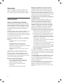
To configure the 10 kW fuel system for LP use:
1. Set generator’s system switch to OFF.
2. Remove 15 Amp fuse from control panel.
3. Open oil fill access panel.
4. Connect the fuel select solenoid by joining the two-pin
electrical connector (C).
5. Reinstall 15 Amp fuse in control panel.
6. Set generator’s system switch to AUTO.
7. Close access panels.
The system is now ready to operate automatically using
LP vapor fuel.
C

20
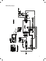
7000 Watt Schematic Diagram
La page est en cours de chargement...
La page est en cours de chargement...
La page est en cours de chargement...
La page est en cours de chargement...
La page est en cours de chargement...
La page est en cours de chargement...
La page est en cours de chargement...
La page est en cours de chargement...
La page est en cours de chargement...
La page est en cours de chargement...
La page est en cours de chargement...
La page est en cours de chargement...
La page est en cours de chargement...
La page est en cours de chargement...
La page est en cours de chargement...
La page est en cours de chargement...
La page est en cours de chargement...
La page est en cours de chargement...
La page est en cours de chargement...
La page est en cours de chargement...
La page est en cours de chargement...
La page est en cours de chargement...
La page est en cours de chargement...
La page est en cours de chargement...
La page est en cours de chargement...
La page est en cours de chargement...
La page est en cours de chargement...
La page est en cours de chargement...
La page est en cours de chargement...
La page est en cours de chargement...
La page est en cours de chargement...
La page est en cours de chargement...
La page est en cours de chargement...
La page est en cours de chargement...
La page est en cours de chargement...
La page est en cours de chargement...
La page est en cours de chargement...
La page est en cours de chargement...
La page est en cours de chargement...
La page est en cours de chargement...
La page est en cours de chargement...
La page est en cours de chargement...
La page est en cours de chargement...
La page est en cours de chargement...
La page est en cours de chargement...
La page est en cours de chargement...
La page est en cours de chargement...
La page est en cours de chargement...
-
 1
1
-
 2
2
-
 3
3
-
 4
4
-
 5
5
-
 6
6
-
 7
7
-
 8
8
-
 9
9
-
 10
10
-
 11
11
-
 12
12
-
 13
13
-
 14
14
-
 15
15
-
 16
16
-
 17
17
-
 18
18
-
 19
19
-
 20
20
-
 21
21
-
 22
22
-
 23
23
-
 24
24
-
 25
25
-
 26
26
-
 27
27
-
 28
28
-
 29
29
-
 30
30
-
 31
31
-
 32
32
-
 33
33
-
 34
34
-
 35
35
-
 36
36
-
 37
37
-
 38
38
-
 39
39
-
 40
40
-
 41
41
-
 42
42
-
 43
43
-
 44
44
-
 45
45
-
 46
46
-
 47
47
-
 48
48
-
 49
49
-
 50
50
-
 51
51
-
 52
52
-
 53
53
-
 54
54
-
 55
55
-
 56
56
-
 57
57
-
 58
58
-
 59
59
-
 60
60
-
 61
61
-
 62
62
-
 63
63
-
 64
64
-
 65
65
-
 66
66
-
 67
67
-
 68
68


Simplicity 040301A-0 Guide d'installation
- Catégorie
- Groupes électrogènes
- Taper
- Guide d'installation
dans d''autres langues
Documents connexes
-
Simplicity 040315GEC-0 Guide d'installation
-
-
-
Briggs & Stratton 18000 Manuel utilisateur
-
-