Pepperl+Fuchs M12/MV12-F1/76b/82b/115/128 Mode d'emploi
- Taper
- Mode d'emploi

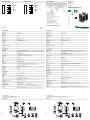
alle Maße in mm
DimensionsAbmessungen
Technische Daten Technical data
Elektrischer Anschluss Electrical connection Adressen/Addresses
Sicherheitshinweise:
• Vor der Inbetriebnahme Betriebsanleitung lesen
• Anschluss, Montage und Einstellung nur durch Fachpersonal
• Kein Sicherheitsbauteil gemäß EU-Maschinenrichtlinie
Security Instructions:
• Read the operating instructions before attempting commissioning
• Installation, connection and adjustments should only be undertaken by specialist personnel
• Not a safety component in accordance with the EU Machinery Directive
all dimensions in mm
www.pepperl-fuchs.com
Pepperl+Fuchs GmbH
68301 Mannheim · Germany
Tel. +49 621 776-4411
Fax +49 621 776-27-4411
Worldwide Headquarters
Pepperl+Fuchs GmbH · Mannheim · Germany
USA Headquarters
Pepperl+Fuchs Inc. · Twinsburg · USA
E-mail: fa-info@us.pepperl-fuchs.com
Asia Pacific Headquarters
Pepperl+Fuchs Pte Ltd · Singapore
Company Registration No. 199003130E
M12x1 M8x1
2
2
1
34
5
III
II
I
T
N
L
D
6
2
4
3
1
53
1
2
4
Stecker um 90° drehbar
Anschlussoptionen
1 Betriebsanzeige grün
2 Schaltanzeige gelb
3 Hell-/Dunkel-Schalter
4 Teach-In Schalter
5 optische Achse
6 Ausrichthilfe/Sender 2
M4 / 4 tief
Festkabel
Gerätestecker M12 Gerätestecker M8
15
10
M12x1
41.5
5.3
65
5.5
19.5
7
24
ø4.5
11.5
12
49
21.3
31.8
2
M8x1
7.5
Einweg-Lichtschranke
mit Festkabel
Thru-beam sensor
with fixed cable
M12/MV12-F1/76b/82b/115/128
Einzelkomponenten
Sender M12-F1/76b/115
Empfänger MV12-F1/82b/115/128
Allgemeine Daten
Betriebsreichweite 0 ... 16 m
Grenzreichweite 25 m
Lichtsender 2 LED
Lichtart rot, Wechsellicht , 660 nm
Hindernisgröße min. 12 mm
Ausrichthilfe LED rot im Empfänger
Lichtfleckdurchmesser ca. 420 mm im Abstand von 16 m
Öffnungswinkel 1,5 °
Fremdlichtgrenze
Gleichlicht 40000 Lux
Wechsellicht 5000 Lux
Kenndaten funktionale Sicherheit
MTTFd 570 a
Gebrauchsdauer (TM) 20 a
Diagnosedeckungsgrad (DC) 90 %
Anzeigen/Bedienelemente
Betriebsanzeige LED grün, blinkend im Kurzschlussfall
Funktionsanzeige 2 LEDs gelb für Schaltzustand, Funktionsreserve, Teach-In Betrieb und Kontrasterkennungsbetrieb
Bedienelemente Drehschalter für hell/dunkel, 5-stufiger mechanischer Schalter zur Einstellung der Kontrasterken-
nungsstufen
Kontrasterkennungsstufen 15 % - Klarglasflaschen
25 % - Kunststofffolien
40 % - Farbglas oder nichttransparente Materialien
einstellbar durch Teach-In-Taste oder externe Leitung
Elektrische Daten
Betriebsspannung UB10 ... 30 V DC
Welligkeit max. 10 %
Leerlaufstrom I0Sender:
≤
35 mA
Empfänger:
≤
45 mA
Eingang
Testeingang Senderabschaltung bei 0 V
Funktionseingang Ext. Teach-In-Eingang (ET)
Ausgang
Vorausfallausgang 1 PNP, inaktiv bei Unterschreiten der Funktionsreserve nach ca. 5 s.
Sofort inaktiv, wenn innerhalb der Blinkzeit 4 Strahlunterbrechungen stattfinden.
Schaltungsart hell-/dunkelschaltend, umschaltbar
Signalausgang 1 Gegentaktausgang, kurzschlussfest, verpolgeschützt
Schaltspannung max. 30 V DC
Schaltstrom max. 0,2 A
Spannungsfall Ud
≤
2,5 V DC
Schaltfrequenz f 1000 Hz
Ansprechzeit 0,5 ms
Umgebungsbedingungen
Umgebungstemperatur -40 ... 60 °C (-40 ... 140 °F)
Lagertemperatur -40 ... 75 °C (-40 ... 167 °F)
Mechanische Daten
Schutzart IP67
Anschluss Festkabel 2500 mm , PUR
Material
Gehäuse Rahmen: Zink-Druckguss, vernickelt
Seitenteile: Kunststoff PC, glasfaserverstärkt
Lichtaustritt Kunststoffscheibe
Masse 120 g (Sender und Empfänger)
Normen- und Richtlinienkonformität
Normenkonformität
Produktnorm EN 60947-5-2:2007
IEC 60947-5-2:2007
Schock- und Stoßfestigkeit IEC / EN 60068, Halb-Sinus, 40 g je X, Y und Z Richtung
Vibrationsfestigkeit IEC / EN 60068-2-6, Sinus, 10 - 150 Hz, 5 g je X, Y und Z Richtung
Zulassungen und Zertifikate
Schutzklasse II, Bemessungsspannung
≤
300 V AC bei Verschmutzungsgrad 1-2 nach IEC 60664-1
UL-Zulassung cULus
CCC-Zulassung Produkte, deren max. Betriebsspannung
≤
36 V ist, sind nicht zulassungspflichtig und daher nicht mit
einer CCC-Kennzeichnung versehen.
M12x1 M8x1
2
2
1
34
5
III
II
I
T
N
L
D
6
2
4
3
1
53
1
2
4
Connector 90° adjustable position
Connection options:
1 Operating display green
2 Switch state yellow
3 Bright/dark switch
4 Teach-In switch
5 Optical axis
6 Alignment aid/emitter 2
M4 / 4 deep
Fixed cable
Unit Connector M12 Unit Connector M8
15
10
M12x1
41.5
5.3
65
5.5
19.5
7
24
ø4.5
11.5
12
49
21.3
31.8
2
M8x1
7.5
07/26/2011
Date:
Option:
ET
Teach
+UB
Q2
0 V
Q1
BU
WH
BN
BK
GR
Alarm
...82b/128
Sender 2-
Abschaltung
Sender
...76b
Test
System components
Emitter M12-F1/76b/115
Receiver MV12-F1/82b/115/128
General specifications
Effective detection range 0 ... 16 m
Threshold detection range 25 m
Light source 2 LED
Light type modulated visible red light , 660 nm
Target size min. 12 mm
Alignment aid LED red in receiver
Diameter of the light spot approx. 420 mm at a distance of 16 m
Angle of divergence 1.5 °
Ambient light limit
Continuous light 40000 Lux
Modulated light 5000 Lux
Functional safety related parameters
MTTFd 570 a
Mission Time (TM) 20 a
Diagnostic Coverage (DC) 90 %
Indicators/operating means
Operating display LED green, flashes in case of short-circuit
Function display 2 LEDs yellow for switching state, stability control, TEACH-IN and contrast detection mode
Controls rotary switch for light/dark, 5-step switch for contrast recognition adjustment
Contrast detection levels 15 % - clear glass bottles
25 % - plastic foils
40 % - colored glass or opaque materials
adjustable by TEACH-IN key or external wire
Electrical specifications
Operating voltage UB10 ... 30 V DC
Ripple max. 10 %
No-load supply current I0Emitter:
≤
35 mA
Receiver:
≤
45 mA
Input
Test input emitter deactivation at 0 V
Function input Ext. Teach-In input (ET)
Output
Output of the pre-fault indication 1 PNP, inactive when level falls below function reserve after approx. 5 s.
Immediately inactive if the beam is interrupted 4 times during the flashtime.
Switching type light/dark on, switchable
Signal output 1 push-pull output, short-circuit protected, reverse polarity protected
Switching voltage max. 30 V DC
Switching current max. 0.2 A
Voltage drop Ud
≤
2.5 V DC
Switching frequency f 1000 Hz
Response time 0.5 ms
Ambient conditions
Ambient temperature -40 ... 60 °C (-40 ... 140 °F)
Storage temperature -40 ... 75 °C (-40 ... 167 °F)
Mechanical specifications
Protection degree IP67
Connection 2500 mm fixed cable , PUR
Material
Housing Frame: nickel plated, die cast zinc,
Laterals: glass-fiber reinforced plastic PC
Optical face Plastic pane
Mass 120 g (emitter and receiver)
Compliance with standards and directives
Standard conformity
Product standard EN 60947-5-2:2007
IEC 60947-5-2:2007
Shock and impact resistance IEC / EN 60068. half-sine, 40 g in each X, Y and Z directions
Vibration resistance IEC / EN 60068-2-6. Sinus. 10 -150 Hz, 5 g in each X, Y and Z directions
Approvals and certificates
Protection class II, rated voltage
≤
300 V AC with pollution degree 1-2 according to IEC 60664-1
UL approval cULus
CCC approval Products with a maximum operating voltage of
≤
36 V do not bear a CCC marking because they do
not require approval.
= Hellschaltung
= Dunkelschaltung = Light on
= Dark on
Option:
ET
Teach
+UB
Q2
0 V
Q1
BU
WH
BN
BK
GR
Alarm
...82b/128
Emitter 2-
switch-off
Emitter
...76b
Test
DIN A3 -> DIN A7
Part. No.: 115972 45-0385C
Doc. No.:

• Schalterstellung "N" (Normalbetrieb):
LEDs leuchten bei freiem Lichtstrahl, blinken bei Unterschreiten der Funktionsreserve, aus bei Strahl-
unterbrechung
• Schalterstellung "T" (Teach-In Betrieb):
LED blinkt nach 1s langsam (ca.1,5 Hz). Der Sensor ist nun bereit, über den mechanischen Schalter
(Stellung I, II, III) oder ein externes Signal (Ext. Teach-Eingang) für einen bestimmten Kontrasterken-
nungswert eingestellt zu werden.
• Schalterstellungen "I", "II" und "III" (Kontrasterkennungs-Betrieb)
Kontrasterkennungswerte: I für 15 %, II für 25 %, III für 40 %
1. LED leuchtet konstant: Lichtweg frei
2. LED aus: Objekt erkannt
3. LED schnell blinkend: keine sicher Erfassung, Verschmutzung zu groß, Funktionsreserve zu gering.
• Ext. Teach-In Eingang
Die gewünschte Kontrasterkennung wird in Schalterstellung T durch Anlegen eines High-Impulses
bestimmter Breite eingestellt.
I: 50 ms (30 ms ... 100 ms)
II: 150 ms (100 ms ... 200 ms)
III: > 200 ms
Mode-Wahlschalter in Stellung T.
• Switch position "N" (standard operation):
LEDs are lit when the light beam is unobstructed, they flash when the value falls short of the function reserve and switch off
when the beam is interrupted.
• Switch position "T" (Teach-In mode):
After 1 s, the LED flashes slowly (approx. 1.5 Hz). The sensor is now ready to be set for a specific contrast detection value eit-
her via the mechanical switch (pos. I, II or III) or an external signal.
• Switch positions "I", "II" and "III" (contrast detection mode)
Contrast recognition values: I for 15 %, II for 25 %, III for 40 %
1. LED permanently lit: light path unobstructed
2. LED off: element to be sensed detected
3. LED flashes rapidly: detection failure, excessive soiling, function reserve too low.
• Ext. Teach-In input
The desired contrast recognition capability can be adjusted by applying of a logic „high“ pulse with a certain pulse length when
the switch is in position T.
I: 50 ms (30 ms ... 100 ms)
II: 150 ms (100 ms ... 200 ms)
III: > 200 ms
Mode selector in position T.
X [m]
Y [mm] M12/MV12...
x
y
50
0
100
150
200
2046810 12 14 16
Charakteristische Ansprechkurve
Courbe de response caractéristique
Curve di risposta caratteristica
Characteristic response curve
Curva de respuesta característica
Möglicher Abstand (Versatz) zwischen
optischer Achse und Referenzobjekt.
Permissible distance (offset) between
optical axis and reference target.
Ecart possible entre l'axe optique et la
cible de référence.
Desplazamiento entre el eje óptico y
objeto de referencia.
Distanza possibile (sfalsato) tra l'asse
ottico e l'ogetto di riferimento.
Funktionsreserve, Stability control, Réserve de fonctionnement,
Reserva de función, Funzione riserva
M12/MV12...
x
1
10
100
1000
10000
0 5 10 15 20 25
Relative Empfangslichtstärke
Intensité relative de la lumière reçue
Intensità relativa luce in ricezione
Relative received light strength
Potencia relativa de recepción lumínica
X [m]
Sender
Emitter
Émetteur
Emisor
Trasmittente
ausrichten
align
aligne
alinea
direzione
Empfänger
receiver
récepteur
receptor
ricevitore
LED
T
Montage und Justage
Montage et Alignement
Montaggio e Aggiustaggio
Mounting and Alignment
Montaje y Ajuste
In Schalterstellung "N" Sender und Empfänger ausrichten bis:
Gelbe LED leuchtet konstant,
rote LED ist aus.
In switching position "N" emitter and receiver align to:
Yellow LED lights up constantly,
red LED is off.
Dans le "N les" expéditeurs et destinataires de position de
commutation alignez :
Jaunissez la DEL s'allume constamment,
DEL rouge est dehors.
En los recipientes "N" de la posición de conmutación los
remitentes y alinean:
El LED amarillo se enciende para arriba constantemente,
LED rojo está hacia fuera.
Nel del "N" di posizione di commutazione i trasmettitori ed i
destinatari si allineano:
Il LED giallo si illumina costantemente in su,
LED rosso è fuori.
Teach-In
LD
-
 1
1
-
 2
2


Pepperl+Fuchs M12/MV12-F1/76b/82b/115/128 Mode d'emploi
- Taper
- Mode d'emploi
dans d''autres langues
Documents connexes
-
Pepperl+Fuchs MLV12-54-LAS/76b/110/124 Mode d'emploi
-
-
-
-
-
-
-
-
-