Delta Children Essex Changing Table/Bookcase Assembly Instructions
- Taper
- Assembly Instructions

Read all instructions
before assembly and use.
KEEP INSTRUCTIONS FOR
FUTURE USE.
Lisez toutes les instructions avant
l’assemblage et l’utilisation.
CONSERVEZ LES INSTRUCTIONS
POUR UN USAGE ULTERIEUR.
Lea todas las instrucciones
antes de ensamblar y usar.
MANTENGA LAS INSTRUCCIONES
PARA SU USO FUTURO.
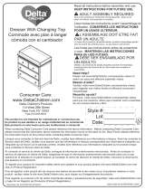
When contacting Delta Consumer Experience Center please reference the above information. Before contacting
Delta Consumer Experience Center please ensure that the information above matches the information found on the
label on the Top Shelf, please reference the information found on the product when contacting Delta Consumer
Experience Center.
Lorsque vous contactez le Service client de Delta, veuillez faire référence aux informations ci-dessus. Avant de
contacter le Service client de Delta, veuillez vous assurer que les informations ci-dessus correspondent aux
informations indiquées sur l’étiquette qui se trouve sur le Tablette supérieur; veuillez faire référence aux informations
indiquées sur le produit lorsque vous contactez le Service client de Delta.
Al contactar al servicio al cliente de Delta, entregue la información anteriormente mencionada. Antes de
contactar al servicio de atención al cliente de Delta, asegúrese de que la información anteriormente mencionada
calza con la que aparece en la etiqueta en el Estante superior; al contactar al centro de atención al cliente de
Delta, mencione la información que aparece en el producto.
CONSUMER EXPERIENCE CENTER
Delta Children’s Products Corp |114 West 26th Street New York, NY 10001
(646) 435-8727 | [email protected] | www.DeltaChildren.com
Style #:
Lot:
Date:
___________
___________
___________
A
REV
This product is not intended for institutional or commercial use.
Ce produit ne pas destine a un usage institutionnel ou commercial.
Este producto no esta hecho para uso institucional o comercial.
ADULT ASSEMBLY REQUIRED
Due to the presence of small parts during assembly, keep out
of reach of children until assembly is complete.
L’ASSEMBLAGE DOIT ETRE FAIT
PAR UN ADULTE
A cause de la presence de petites pieces, pendant l’assemblage
gardez hors de portee des enfants jusqu'a ce que celui-ci soit
termine.
DEBE SER ENSAMBLADO
POR UN ADULTO
Debido a la presencia de piezas pequeñas durante el
ensamblaje, mantenga fuera del alcance de los niños hasta que
complete el ensamblaje.
NEED EXTRA HELP?
We make assembly easy with
our tips & tricks video
https://www.deltachildren.com/
pages/instructions
BESOIN D'AIDE SUPPLÉMENTAIRE?
Nous facilitons l'assemblage avec
nos trucs et astuces vidéo
https://www.deltachildren.com/
pages/instructions
¿NECESITA AYUDA EXTRA?
Hacemos el montaje fácil con
nuestros consejos y trucos video
https://www.deltachildren.com/
pages/instructions
June 21, 2019, 29385, R0
©2019 DELTA ENTERPRISE CORP.
ASSEMBLY INSTRUCTIONS • INSTRUCTIONS DE MONTAGE • INSTRUCCIONES DE MONTAJE
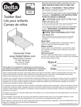
Changing Table
Table à Langer
Cambiador
La page est en cours de chargement...

REMARQUES SUR L’ASSEMBLAGE :
-Lors de l’assemblage, quand vous utilisez vis ou boulons, verifiez chaque piece en placant le vis/boulon
sur le diagramme de la piece concernee qui est dessine en taille et forme reelle. Assurez vous d’utiliser
la taille et la forme exacte comme il est specifie dans les instructions.
-Pour assembler cet element vous pourriez avoir besoin de le placer sur le cote lateral et sur le cote
frontal. Il est fortement recommandé de faire l’assemblage sur une surface lisse, non abrasive (comme
le film mousse de l'emballage)pour eviter d’endommager les finitions.
REMARQUES SUR LE SOIN ET L’ENTRETIEN :
-Ne pas rayer ou ebrecher la finition.
-Examinez de pres le produit regulierement, contactez Delta Children’s Products pour les pieces de
rechange ou pour poser des questions.
-Ne pas ranger le produit ou des pieces a des temperatures extremes ou dans des conditions comme
un grenier chaud ou une cave froide et humide. Ces extremes peuvent causer une perte de l’integrite de
la structure du produit
-Pour préserver le lustre original et la beauté de ce fini raffiné nettoyer avec un chiffon humide, puis un
chiffon sec.
-Ne pas utiliser des produits chimiques abrasifs
-Ne pas pulveriser un nettoyant directement sur le meuble, pulveriser sur le torchon et puis appliquer
sur le meuble. Testez le produit nettoyant sur un endroit discret avant de l’utiliser sur la totalite du
meuble
-Lors d’un deplacement sur une moquette ou tapis, soulevez legerement le meuble pour eviter de
casser les pieds.
-L’utilisation d’un vaporisateur pres du meuble causera le gonflement du bois et l’ecaillage de la finition.
REMARQUES SUR L’UTILISATION :
Assurez la securite des enfants et des autres en suivant ces simples regles :
-Ne pas autoriser les enfants a jouer sur un meuble.
-Ne pas autoriser l’escalade d’aucun meuble.
-Ne pas autoriser a se suspendre d’aucun meuble.
-Toujours surveiller l’activite de votre enfant lors qu’il se trouve dans sa chambre.
Danger de chutes. Des enfants ont souffert de sérieuses blessures après être tombés des tables à langer.
Les chutes peuvent arriver rapidement.
•RESTEZ à portée de bras de l'enfant.
•Lisez toutes les instructions avant d’utiliser la table à langer
•CONSERVER CES INSTRUCTIONS DANS UN ENDROIT SÛR POUR RÉFÉRENCE ULTÉRIEURE.
•Inspecter régulièrement la table à langer. Ne pas l’utiliser si elle est endommagée ou brisée. Si vous avez
des questions contactez Delta Children's Products.
•Serrer tous les boulons et vis desserrés avant chaque usage.
•La table à langer ne doit pas être utilisée pour un enfant pesant plus de 13,5 kg (30 lb.).
•Utiliser exclusivement le matelas à langer fourni par Delta Children’s Products.
AVERTISSEMENT
3
La page est en cours de chargement...
La page est en cours de chargement...

ASSEMBLY INSTRUCTIONS • INSTRUCTIONS DE MONTAGE • INSTRUCCIONES DE MONTAJEASSEMBLY INSTRUCTIONS • INSTRUCTIONS DE MONTAGE • INSTRUCCIONES DE MONTAJEASSEMBLY INSTRUCTIONS • INSTRUCTIONS DE MONTAGE • INSTRUCCIONES DE MONTAJE
DELTA CHILDREN
@deltachildren
SUIVEZ NOUS POUR AVOIR PLUS DE CHANCES DE GAGNER /
SÍGANOS PARA TENER MAS CHANCES DE GANAR
SCANNEZ ICI / ESCANEE AQUÍ
Pour plus d'informations et
pour voir tous nos produits
Para más información y para
ver todos nuestros productos
ÉCONOMISEZ BEAUCOUP AVEC
AHORRE MUCHO CON
Visitez Deltachilren.com Pour Commencer Vos Achats
Visita Deltachilren.com Para Comenzar A Comprar
FAMILLE DELTA
Bienvenue dans la
Voici Notre Cadeau Pour Vous
Votre Prochain Achat Chez
*Subject to Change
*Exclusions Apply
*Des exclusions s’appliquent
*Sujet à changement
Aquí Está Nuestro Regalo Para Usted
FAMILIA DELTA
Bienvenido a la
Su Próxima Compra En
DeltaChildren.com
DELTA10
UTILISEZ LE CODE:
UTILICE EL CÓDIGO:
ECRIVEZ UN COMMENTAIRE CLIENT pour ce produit sur le site web du magasin où il a été acheté
CALIFIQUE EL PRODUCTO en la página web de la tienda donde haya sido comprado
1
FAITES UNE CAPTURE D’ECRAN de votre commentaire client et mettez la en ligne sur www.DeltaChildren.com/Review
HAGA UNA CAPTURA DE PANTALLA de su calificación y cárguela a la pagina www.DeltaChildren.com/Review
2
C’EST AUSSI SIMPLE QUE ÇA! Dès que c’est fait vous serez instantanément INSCRIT POUR GAGNER 2500$
ES ASÍ DE FÁCIL! En cuanto lo envíe ya estará instantáneamente PARTICIPANDO PARA GANAR $2.500
3
REGLEMENT DE PARTICIPATION / REGLAS PARA PARTICIPAR
LAISSEZ UN COMMENTAIRE CLIENT POUR GAGNER $2500
CALIFIQUE EL PRODUCTO PARA GANAR $2500
6

ASSEMBLY INSTRUCTIONS • INSTRUCTIONS DE MONTAGE • INSTRUCCIONES DE MONTAJE
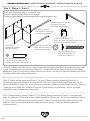
PARTS: MAKE SURE THAT ALL PRE-ASSEMBLED PARTS ARE TIGHT
PIÈCES : VÉRIFIEZ QUE TOUTES LES PIÈCES PRÉ-MONTÉES SONT BIEN SERRÉES.
PIEZAS: ASEGÚRESE DE QUE TODAS LAS PIEZAS PRE-ENSAMBLADAS ESTÁN BIEN APRETADAS.
ASSEMBLY INSTRUCTIONS • INSTRUCTIONS DE MONTAGE • INSTRUCCIONES DE MONTAJE
7
A. Left Side x 1
Côté gauche x 1
Lado izquierdo x 1
29365
H. Top Shelf x 1
Tablette supérieur x 1
Estante superior x 1
29367
J. Middle Shelf x 1
Tablette central x 1
Estante Medio x 1
29368
K. Bottom Shelf x 1
Tablette inférieur x 1
Estante inferior x 1
29369
B. Right Side x 1
Côté droit x 1
Lado derecho x 1
29366
C. Back Top Rail x 1
Barre arrière supérieur x 1
Barra trasero superior x 1
29374
E. Back Bottom Rail x 2
Barre arrière inférieur x 2
Barra trasero inferior x 2
29376
G. Front Bottom Rail x 1
Barre avant inférieur x 1
Barra frontal inferior x 1
29373
L. Upper Back Panel x 1
Panneau arrière Supérieur x 1
Panel Trasero Superior x 1
29377
M. Lower Back Panel x 1
Panneau arrière Inférieur x 1
Panel Inferior Trasero x 1
29378
F. Front Top Rail x 1
Barre avant supérieur x 1
Barra frontal superior x 1
29372

N. Top Divider x 1
Diviseur supérieur x 1
Divisor Superior x 1
29370
P. Bottom Divider x 1
Diviseur inférieur x 1
Divisor Inferior x 1
29371
ASSEMBLY INSTRUCTIONS • INSTRUCTIONS DE MONTAGE • INSTRUCCIONES DE MONTAJEASSEMBLY INSTRUCTIONS • INSTRUCTIONS DE MONTAGE • INSTRUCCIONES DE MONTAJE
R. Foot (x4 Painted and x4 Natural color)
Pied (peints x4 et de couleur naturelle x4)
Pie (pintado x4 y color natural x4)
29379
S. Changing Top Back x 1
Partie postérieure du plan à langer x 1
Parte posterior del cambiador x 1
29380
U. Changing Top Left Side x 1
Coté gauche du plan à langer x 1
Lado izquierdo del cambiador x 1
29382
V. Changing Top Right side x 1
Coté droit du plan à langer x 1
Lado derecho del cambiador x 1
29383
T. Changing Top Front x 1
Partie frontale du plan à langer x 1
Parte frontal del cambiador x 1
29381
8

ASSEMBLY INSTRUCTIONS • INSTRUCTIONS DE MONTAGE • INSTRUCCIONES DE MONTAJEASSEMBLY INSTRUCTIONS • INSTRUCTIONS DE MONTAGE • INSTRUCCIONES DE MONTAJE
Parts: Hardware kits part#29384
Pièces: L'ensemble de quincaillerie - pièce n°29384
Piezas: El kit de herramientas - Pieza #29384
X. M6 x 40 mm Bolt x 4
Boulon M6 x 40 mm x 4
Perno M6 x 40mm x 4
5465
Y. M6 x 30 mm Bolt x 4
Boulon M6 x 30 mm x 4
Perno M6 x 30mm x 4
5463
W. M6 x 50 mm Bolt x 29
Boulon M6 x 50 mm x 29
Perno M6 x 50mm x 29
5467
Z. M6x13mm Barrel Nut x 29
Écrous À Portée Cylindrique M6x13 mm x 29
Tuerca Cilíndrica M6x13mm x 29
5483
M4 Allen Wrench (included)
Clé Allen M4 (inclus)
Llave Allen M4 (incluido)
1177
CC. 15 mm Screw x 20
Vis de 15 mm x 20
Tornillo de 15 mm x 20
5577
BB. 37 mm Screw x 3
Vis de 37 mm x 3
Tornillo de 37 mm x 3
5800
Flat Head Screwdriver (not supplied)
Tournevis à tête plate (non fourni)
Destornillador plano (no suministrado)
Phillips Screwdriver (Not Provided)
Tournevis’Phillips’(Non Prévu)
Destornillardor’Phillips’(No siempre)
No drills necessary. Do not use power
screwdriver.
Aucun forage n’est nécessaire. Ne pas
utiliser de tournevis électrique.
No hace falta taladrar No utilice
destornilladores eléctricos
AA. Φ6x30 mm Wood Dowel x 32
Cheville en bois Φ6x30mm x 32
Pasador de madera Φ6x30mm x 32
4491
9
YY. Short Screw x1
Vis Court
Tornillo corto
XX. Long Screw x1
Vis Longue
Tornillo Largo
TT. Washer x2
Rondelle
Arandela
ZZ. (1) Wall Strap/Sangle murale/Abrazadera

ASSEMBLY INSTRUCTIONS • INSTRUCTIONS DE MONTAGE • INSTRUCCIONES DE MONTAJEASSEMBLY INSTRUCTIONS • INSTRUCTIONS DE MONTAGE • INSTRUCCIONES DE MONTAJE
10
Step 1 / Étape 1 / Paso 1
Parts and tools required to complete step
Pièces et outils nécessaires au montage
Piezas y herramientas necesarias para completar este paso
Z. M6x13mm Barrel Nut x 2
Écrous À Portée Cylindrique M6x13 mm x 2
Tuerca Cilíndrica M6x13mm x 2
M4 Allen Wrench (included)
Clé Allen M4 (inclus)
Llave Allen M4 (incluido)
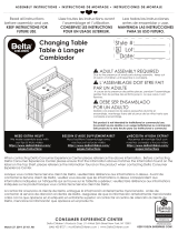
Attach the Middle Shelf (Part J) to the Left Side (Part A) with (2) Φ6x30 mm Wood Dowels (Part
AA), (2) M6x50mm Bolts (Part W) and (2) M6x13mm Barrel Nuts (Part Z) using the M4 Allen
Wrench as shown. Use the Flat Head Screwdriver to hold the Barrel Nut in the proper
alignment.
Fixez le Tablette central (Pièce J) au Côté gauche (Pièce A) à l’aide de (2) Cheville en bois Φ
6x30mm (Pièce AA), de (2) Boulons M6x50mm (Pièce W) et de (2) Écrou à portée cylindrique
M6x13mm (Pièce Z). Serrer à l’aide de la clé Allen M4. Utiliser le tournevis à tête plate pour
maintenir l’écrou à portée cylindrique dans l'alignement approprié.
Fije la Estante Medio (Pieza J) al Lado izquierdo (Pieza A) utilizando (2) Pasadores de madera
Φ6x30mm (Pieza AA), (2) Pernos M6x50mm (Pieza W) y (2) Tuercas cilíndricas M6x13mm (Pieza
Z). Utilice la Llave Allen M4 para el proceso de apriete. Utilice el Destornillador de Paleta para
mantener la Tuerca Cilíndrica alineado correctamente.
AA. Φ6x30 mm Wood Dowel x 2
Cheville en bois Φ6x30mm x 2
Pasador de madera Φ6x30mm x 2
A. Left Side x 1
Côté gauche x 1
Lado izquierdo x 1
W. M6 x 50 mm Bolt x 2
Boulon M6 x 50 mm x 2
Perno M6 x 50mm x 2
J. Middle Shelf x 1
Tablette central x 1
Estante Medio x 1
La page est en cours de chargement...

From Step 1
À partir de l’étape 1
Desde el paso 1
ASSEMBLY INSTRUCTIONS • INSTRUCTIONS DE MONTAGE • INSTRUCCIONES DE MONTAJEASSEMBLY INSTRUCTIONS • INSTRUCTIONS DE MONTAGE • INSTRUCCIONES DE MONTAJE
12
Step 2 / Étape 2 / Paso 2
Parts and tools required to complete step
Pièces et outils nécessaires au montage
Piezas y herramientas necesarias para completar este paso
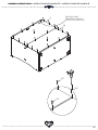
Attach the Top Divider (Part N) and the Bottom Divider (Part P) to the Middle Shelf (Part J)
using (4) Φ6x30 mm Wood Dowels (Part AA) as shown.
Fixez le Diviseur supérieur (pièce N) et le Diviseur inférieur (pièce P) à la tablette centrale
(pièce J) à l'aide de (4) Cheville en bois Φ 6x30mm (Pièce AA), comme indiqué.
Conecte el divisor superior (Parte N) y el divisor inferior (Parte P) al estante medio (Parte J)
utilizando (4) c Pasadores de madera Φ6x30mm (Pieza AA) como se muestra.
AA. Φ6x30 mm Wood Dowel x 4
Cheville en bois Φ6x30mm x 4
Pasador de madera Φ6x30mm x 4
N. Top Divider x 1
Diviseur supérieur x 1
Divisor Superior x 1
P. Bottom Divider x 1
Diviseur inférieur x 1
Divisor Inferior x 1
La page est en cours de chargement...

From Step 2
À partir de l’étape 2
Desde el paso 2
ASSEMBLY INSTRUCTIONS • INSTRUCTIONS DE MONTAGE • INSTRUCCIONES DE MONTAJEASSEMBLY INSTRUCTIONS • INSTRUCTIONS DE MONTAGE • INSTRUCCIONES DE MONTAJE
14
Step 3 / Étape 3 / Paso 3
Parts and tools required to complete step
Pièces et outils nécessaires au montage
Piezas y herramientas necesarias para completar este paso
Z. M6x13mm Barrel Nut x 6
Écrous À Portée Cylindrique M6x13 mm x 6
Tuerca Cilíndrica M6x13mm x 6
M4 Allen Wrench (included)
Clé Allen M4 (inclus)
Llave Allen M4 (incluido)
Attach (1) Back Top Rail (Part C) and (2) Back Bottom Rails (Part E) to the assembly from step
2 with (3) Φ6x30 mm Wood Dowels (Part AA), (6) M6x50mm Bolts (Part W) and (6) M6x13mm
Barrel Nuts (Part Z) using the M4 Allen Wrench as shown. Use the Flat Head Screwdriver to hold
the Barrel Nut in the proper alignment.
Fixez (1) Barre arrière supérieur (Pièce C) et de (2) Barres arrière inférieures (Pièce E) à
l’ensemble monté à l’étape 2 à l’aide de (3) Cheville en bois Φ6x30mm (Pièce AA), de (6)
Boulons M6x50mm (Pièce W) et de (6) Écrou à portée cylindrique M6x13mm (Pièce Z). Serrer à
l’aide de la clé Allen M4. Utiliser le tournevis à tête plate pour maintenir l’écrou à portée
cylindrique dans l'alignement approprié.
Fije (1) Barra trasero superior (Pieza C) y (2) Barras trasero inferiores (Pieza E) a la pieza del
paso 2 utilizando (3) Pasadores de madera Φ6x30mm (Pieza AA), (6) Pernos M6x50mm (Pieza
W) y (6) Tuercas cilíndricas M6x13mm (Pieza Z). Utilice la Llave Allen M4 para el proceso de
apriete. Utilice el Destornillador de Paleta para mantener la Tuerca Cilíndrica alineado
correctamente.
AA. Φ6x30 mm Wood Dowel x 3
Cheville en bois Φ6x30mm x 3
Pasador de madera Φ6x30mm x 3
W. M6 x 50 mm Bolt x 6
Boulon M6 x 50 mm x 6
Perno M6 x 50mm x 6
C. Back Top Rail x 1
Barre arrière supérieur x 1
Barra trasero superior x 1
E. Back Bottom Rail x 2
Barre arrière inférieur x 2
Barra trasero inferior x 2
La page est en cours de chargement...

From Step 3
À partir de l’étape 3
Desde el paso 3
ASSEMBLY INSTRUCTIONS • INSTRUCTIONS DE MONTAGE • INSTRUCCIONES DE MONTAJEASSEMBLY INSTRUCTIONS • INSTRUCTIONS DE MONTAGE • INSTRUCCIONES DE MONTAJE
16
Step 4 / Étape 4 / Paso 4
Parts and tools required to complete step
Pièces et outils nécessaires au montage
Piezas y herramientas necesarias para completar este paso
Z. M6x13mm Barrel Nut x 2
Écrous À Portée Cylindrique M6x13 mm x 2
Tuerca Cilíndrica M6x13mm x 2
M4 Allen Wrench (included)
Clé Allen M4 (inclus)
Llave Allen M4 (incluido)
AA. Φ6x30 mm Wood Dowel x 3
Cheville en bois Φ6x30mm x 3
Pasador de madera Φ6x30mm x 3
W. M6 x 50 mm Bolt x 2
Boulon M6 x 50 mm x 2
Perno M6 x 50mm x 2
G. Front Bottom Rail x 1
Barre avant inférieur x 1
Barra frontal inferior x 1
F. Front Top Rail x 1
Barre avant supérieur x 1
Barra frontal superior x 1
Attach (1) Front Top Rail (Part F) and (1) Front Bottom Rail (Part G) to the assembly from step 3
with (3) Φ6x30 mm Wood Dowels (Part AA), (2) M6x50mm Bolts (Part W) and (2) M6x13mm
Barrel Nuts (Part Z) using the M4 Allen Wrench as shown. Use the Flat Head Screwdriver to hold
the Barrel Nut in the proper alignment.
Fixez (1) Barre avant supérieur (Pièce F) et de (1) Barre avant inférieur (Pièce G) à l’ensemble
monté à l’étape 3 à l’aide de (3) Cheville en bois Φ6x30mm (Pièce AA), de (2) Boulons
M6x50mm (Pièce W) et de (2) Écrou à portée cylindrique M6x13mm (Pièce Z). Serrer à l’aide
de la clé Allen M4. Utiliser le tournevis à tête plate pour maintenir l’écrou à portée cylindrique
dans l'alignement approprié.
Fije (1) Barra frontal superior (Pieza F) y (1) Barra frontal inferior (Pieza G) a la pieza del paso 3
utilizando (3) Pasadores de madera Φ6x30mm (Pieza AA), (2) Pernos M6x50mm (Pieza W) y (2)
Tuercas cilíndricas M6x13mm (Pieza Z). Utilice la Llave Allen M4 para el proceso de apriete.
Utilice el Destornillador de Paleta para mantener la Tuerca Cilíndrica alineado
correctamente.
La page est en cours de chargement...

From Step 4
À partir de l’étape 4
Desde el paso 4
ASSEMBLY INSTRUCTIONS • INSTRUCTIONS DE MONTAGE • INSTRUCCIONES DE MONTAJEASSEMBLY INSTRUCTIONS • INSTRUCTIONS DE MONTAGE • INSTRUCCIONES DE MONTAJE
18
Step 5 / Étape 5 / Paso 5
Parts and tools required to complete step
Pièces et outils nécessaires au montage
Piezas y herramientas necesarias para completar este paso
Z. M6x13mm Barrel Nut x 7
Écrous À Portée Cylindrique M6x13 mm x 7
Tuerca Cilíndrica M6x13mm x 7
M4 Allen Wrench (included)
Clé Allen M4 (inclus)
Llave Allen M4 (incluido)
Attach the Right Side (Part B) to the assembly from step 4 with (8) Φ6x30 mm Wood Dowels
(Part AA), (7) M6x50mm Bolts (Part W) and (7) M6x13mm Barrel Nuts (Part Z) using the M4 Allen
Wrench as shown. Use the Flat Head Screwdriver to hold the Barrel Nut in the proper
alignment.
Fixez le Côté droit (Pièce B) à l’ensemble monté à l’étape 4 à l’aide de (8) Cheville en bois Φ
6x30mm (Pièce AA), de (7) Boulons M6x50mm (Pièce W) et de (7) Écrou à portée cylindrique
M6x13mm (Pièce Z). Serrer à l’aide de la clé Allen M4. Utiliser le tournevis à tête plate pour
maintenir l’écrou à portée cylindrique dans l'alignement approprié.
Fije la Lado derecho (Pieza B) a la pieza del paso 4 utilizando (8) Pasadores de madera Φ
6x30mm (Pieza AA), (7) Pernos M6x50mm (Pieza W) y (7) Tuercas cilíndricas M6x13mm (Pieza
Z). Utilice la Llave Allen M4 para el proceso de apriete. Utilice el Destornillador de Paleta para
mantener la Tuerca Cilíndrica alineado correctamente.
AA. Φ6x30 mm Wood Dowel x 8
Cheville en bois Φ6x30mm x 8
Pasador de madera Φ6x30mm x 8
W. M6 x 50 mm Bolt x 7
Boulon M6 x 50 mm x 7
Perno M6 x 50mm x 7
B. Right Side x 1
Côté droit x 1
Lado derecho x 1
La page est en cours de chargement...

Attach the Bottom Shelf (Part K) to the assembly from step 5 with (8) Φ6x30 mm Wood Dowels
(Part AA), (8) M6x50mm Bolts (Part W) and (8) M6x13mm Barrel Nuts (Part Z) using the M4 Allen
Wrench as shown. Use the Flat Head Screwdriver to hold the Barrel Nut in the proper
alignment.
Fixez le Tablette inférieur (Pièce K) à l’ensemble monté à l’étape 5 à l’aide de (8) Cheville en
bois Φ6x30mm (Pièce AA), de (8) Boulons M6x50mm (Pièce W) et de (8) Écrou à portée
cylindrique M6x13mm (Pièce Z). Serrer à l’aide de la clé Allen M4. Utiliser le tournevis à tête
plate pour maintenir l’écrou à portée cylindrique dans l'alignement approprié.
Fije la Estante inferior (Pieza K) a la pieza del paso 5 utilizando (8) Pasadores de madera Φ
6x30mm (Pieza AA), (8) Pernos M6x50mm (Pieza W) y (8) Tuercas cilíndricas M6x13mm (Pieza
Z). Utilice la Llave Allen M4 para el proceso de apriete. Utilice el Destornillador de Paleta para
mantener la Tuerca Cilíndrica alineado correctamente.
From Step 5
À partir de l’étape 5
Desde el paso 5
ASSEMBLY INSTRUCTIONS • INSTRUCTIONS DE MONTAGE • INSTRUCCIONES DE MONTAJEASSEMBLY INSTRUCTIONS • INSTRUCTIONS DE MONTAGE • INSTRUCCIONES DE MONTAJE
20
Step 6 / Étape 6 / Paso 6
Parts and tools required to complete step
Pièces et outils nécessaires au montage
Piezas y herramientas necesarias para completar este paso
Z. M6x13mm Barrel Nut x 8
Écrous À Portée Cylindrique M6x13 mm x 8
Tuerca Cilíndrica M6x13mm x 8
M4 Allen Wrench (included)
Clé Allen M4 (inclus)
Llave Allen M4 (incluido)
AA. Φ6x30 mm Wood Dowel x 8
Cheville en bois Φ6x30mm x 8
Pasador de madera Φ6x30mm x 8
W. M6 x 50 mm Bolt x 8
Boulon M6 x 50 mm x 8
Perno M6 x 50mm x 8
K. Bottom Shelf x 1
Tablette inférieur x 1
Estante inferior x 1
La page est en cours de chargement...

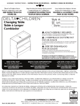
Attach the Top Shelf (Part H) to the assembly from step 6 with (4) Φ6x30 mm Wood Dowels
(Part AA), (4) M6x40mm Bolts (Part X) and (4) M6x30mm Bolts (Part Y) using the M4 Allen
Wrench as shown.
Fixez le Tablette supérieur (Pièce H) à l’ensemble monté à l’étape 6 à l’aide de (4) Cheville en
bois Φ6x30mm (Pièce AA), de (4) Boulons M6x40mm (Pièce X) et de (4) Boulons M6x30mm
(Pièce Y). Serrer à l’aide de la clé Allen M4.
Fije la Estante superior (Pieza H) a la pieza del paso 6 utilizando (4) Pasadores de madera Φ
6x30mm (Pieza AA), (4) Pernos M6x40mm (Pieza X) y (4) Pernos M6x30mm (Pieza Y). Utilice la
Llave Allen M4 para el proceso de apriete.
From Step 6
À partir de l’étape 6
Desde el paso 6
ASSEMBLY INSTRUCTIONS • INSTRUCTIONS DE MONTAGE • INSTRUCCIONES DE MONTAJEASSEMBLY INSTRUCTIONS • INSTRUCTIONS DE MONTAGE • INSTRUCCIONES DE MONTAJE
22
Step 7 / Étape 7 / Paso 7
Parts and tools required to complete step
Pièces et outils nécessaires au montage
Piezas y herramientas necesarias para completar este paso
M4 Allen Wrench (included)
Clé Allen M4 (inclus)
Llave Allen M4 (incluido)
AA. Φ6x30 mm Wood Dowel x 4
Cheville en bois Φ6x30mm x 4
Pasador de madera Φ6x30mm x 4
H. Top Shelf x 1
Tablette supérieur x 1
Estante superior x 1
X. M6 x 40 mm Bolt x 4
Boulon M6 x 40 mm x 4
Perno M6 x 40mm x 4
Y. M6 x 30 mm Bolt x 4
Boulon M6 x 30 mm x 4
Perno M6 x 30mm x 4
La page est en cours de chargement...

ASSEMBLY INSTRUCTIONS • INSTRUCTIONS DE MONTAGE • INSTRUCCIONES DE MONTAJEASSEMBLY INSTRUCTIONS • INSTRUCTIONS DE MONTAGE • INSTRUCCIONES DE MONTAJE
24
Step 8 / Étape 8 / Paso 8
Parts and tools required to complete step
Pièces et outils nécessaires au montage
Piezas y herramientas necesarias para completar este paso
CC. 15 mm Screw x 20
Vis de 15 mm x 20
Tornillo de 15 mm x 20
From Step 7
À partir de l’étape 7
Desde el paso 7
Phillips Screwdriver (Not Provided)
Tournevis’Phillips’(Non Prévu)
Destornillardor’Phillips’(No siempre)
L. Upper Back Panel x 1
Panneau arrière Supérieur x 1
Panel Trasero Superior x 1
M. Lower Back Panel x 1
Panneau arrière Inférieur x 1
Panel Inferior Trasero x 1
Attach (1) Upper Back Panel (Part L) and (1) Lower Back Panel (Part M) to the assembly from
step 7 using (20) 15 mm Screws (Part CC). Tighten with the Phillips Screwdriver. Ensure the
Address Label is facing to the back of the unit.
Fixez (1) Panneau arrière Supérieur (Pièce L) et (1) Panneau arrière Inférieur (Pièce M) à
l’ensemble monté à l’étape 7 à l’aide de (20) vis 15mm (Pièce CC). Serrez à l'aide d’un
tournevis Phillips. Assurez-vous que l’étiquette d’adresse est orientée vers le dos de l’unité.
Fije el panel posterior superior (Pieza L) y el panal posterior inferior (Pieza M) al conjunto de
piezas del Paso 7 utilizando (20) tornillos 15mm (Pieza CC). Apriete utilizando un destornillador
Phillips. Asegúrese de que la etiqueta de dirección enfrente la parte posterior de la unidad.
La page est en cours de chargement...

You have the option to attach either the (4) painted feet or the (4) natural color feet (Part R)
to the bottom of the case by hand, screwing them into the holes. Make sure all feet are tight
before standing your case back up.
Vous avez la possibilité d’attacher les (4) pieds peints ou les (4) pieds de couleur naturelle
(pièce R) au bas de la bibliothèque, en les vissant dans les trous. Assurez-vous que tous les
pieds sont fermement serrés avant de relever le Commode.
Tiene la opción de fijar los (4) pies pintados o los (4) pies de color natural (Pieza R) hacia la
parte inferior del mueble, atornillando a mano. Asegúrese de que todos los pies estén
apretados antes de volver a colocar el Cómoda derecho.
ASSEMBLY INSTRUCTIONS • INSTRUCTIONS DE MONTAGE • INSTRUCCIONES DE MONTAJEASSEMBLY INSTRUCTIONS • INSTRUCTIONS DE MONTAGE • INSTRUCCIONES DE MONTAJE
26
Step 9 / Étape 9 / Paso 9
Parts and tools required to complete step
Pièces et outils nécessaires au montage
Piezas y herramientas necesarias para completar este paso
From Step 8
À partir de l’étape 8
Desde el paso 8
R. Foot (x4 Painted and x4 Natural color)
Pied (peints x4 et de couleur naturelle x4)
Pie (pintado x4 y color natural x4)
La page est en cours de chargement...

ASSEMBLY INSTRUCTIONS • INSTRUCTIONS DE MONTAGE • INSTRUCCIONES DE MONTAJEASSEMBLY INSTRUCTIONS • INSTRUCTIONS DE MONTAGE • INSTRUCCIONES DE MONTAJE
28
Step 10 / Étape 10 / Paso 10
Parts and tools required to complete step
Pièces et outils nécessaires au montage
Piezas y herramientas necesarias para completar este paso
Z. M6x13mm Barrel Nut x 2
Écrous À Portée Cylindrique M6x13 mm x 2
Tuerca Cilíndrica M6x13mm x 2
M4 Allen Wrench (included)
Clé Allen M4 (inclus)
Llave Allen M4 (incluido)
1. Attach Changing Top Right Side (Part V) to the Changing Top Front (Part T) using (1) Barrel
Nut (Part Z) and (1) 50mm Bolt (Part W). Tighten with the Allen Wrench.
2. Attach Changing Top Left Side (Part U) in the same manner
1. Fixer le coté droit du plan à langer (Pièce V) à la partie frontale du plan à langer (Pièce T) à
l’aide de (1) Écrou à portée cylindrique (Pièce Z) et (1) Boulon 50mm (Pièce W). Serrez avec la
Clé Allen.
2. Fixer le coté gauche du plan à langer (Pièce U) de la même façon.
1. Fijar el lado derecho del cambiador (pieza V) con la parte frontal del cambiador (pieza T)
utilizando (1) Tuerca cilíndrica (Pieza Z) y (1) perno de 50mm (pieza W). Apriete con la Llave
Allen.
2. Fijar el lado izquierdo del cambiador (pieza U) de la misma manera.
W. M6 x 50 mm Bolt x 2
Boulon M6 x 50 mm x 2
Perno M6 x 50mm x 2
U. Changing Top Left Side x 1
Coté gauche du plan à langer x 1
Lado izquierdo del cambiador x 1
V. Changing Top Right side x 1
Coté droit du plan à langer x 1
Lado derecho del cambiador x 1
T. Changing Top Front x 1
Partie frontale du plan à langer x 1
Parte frontal del cambiador x 1
La page est en cours de chargement...

From Step 10
À partir de l’étape 10
Desde el paso 10
ASSEMBLY INSTRUCTIONS • INSTRUCTIONS DE MONTAGE • INSTRUCCIONES DE MONTAJEASSEMBLY INSTRUCTIONS • INSTRUCTIONS DE MONTAGE • INSTRUCCIONES DE MONTAJE
30
Step 11 / Étape 11 / Paso 11
Parts and tools required to complete step
Pièces et outils nécessaires au montage
Piezas y herramientas necesarias para completar este paso
Z. M6x13mm Barrel Nut x 2
Écrous À Portée Cylindrique M6x13 mm x 2
Tuerca Cilíndrica M6x13mm x 2
M4 Allen Wrench (included)
Clé Allen M4 (inclus)
Llave Allen M4 (incluido)
Attach Changing Top Back (Part S) to the Right and Left Sides using (2) M6x50mm bolts (part
W) and (2) Barrel Nuts (Part Z) . Tighten with the Allen Wrench.
Fixer la partie postérieure du plan à langer (Pièce S) au cotés droit et gauche à l’aide de (2)
boulons M6 x 50 mm (Pièce W) et d’(2) écrou à manchon (Pièce Z). Serrez avec la Clé Allen.
Fijar la parte posterior del cambiador (Pieza S) a los lados derecho e izquierdo (2) Tuerca
cilíndrica (Pieza Z) and (2) pernos de 50mm (pieza W). Apriete con la Llave Allen.
W. M6 x 50 mm Bolt x 2
Boulon M6 x 50 mm x 2
Perno M6 x 50mm x 2
S. Changing Top Back x 1
Partie postérieure du plan à langer x 1
Parte posterior del cambiador x 1
La page est en cours de chargement...

ASSEMBLY INSTRUCTIONS • INSTRUCTIONS DE MONTAGE • INSTRUCCIONES DE MONTAJEASSEMBLY INSTRUCTIONS • INSTRUCTIONS DE MONTAGE • INSTRUCCIONES DE MONTAJE
32
Step 12 / Étape 12 / Paso 12
Parts and tools required to complete step
Pièces et outils nécessaires au montage
Piezas y herramientas necesarias para completar este paso
From Step 11
À partir de l’étape 11
Desde el paso 11
From Step 9
À partir de l’étape 9
Desde el paso 9
Phillips Screwdriver (Not Provided)
Tournevis’Phillips’(Non Prévu)
Destornillardor’Phillips’(No siempre)
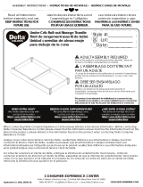
1. Set the Assembled Changing Top on the top of the Dresser as shown.
2. Insert (3) 37mm screws (Part FF) through the back of the Changing Top, into the pre drilled
holes the dresser.
3. Tighten with a Phillips Screwdriver.
1. Placer la Table à Langer maintenant assemblée sur le dessus de la commode.
2. Insérer (3) vis 37 mm (pièce FF) à partir de l’arrière de la table à langer, jusque dans les trous
de guidage que l’on vient de percer dans la commode.
3. Serrer au moyen d’un tournevis Phillips.
1. Poner el equipó de ensamblaje encima del cambiador.
2.Inserta (3) tornillos 37 mm (pieza FF) en la parte de atrás en los agujeros pilotos.
3.Apriete con destornillador Phillips.
BB. 37 mm Screw x 3
Vis de 37 mm x 3
Tornillo de 37 mm x 3
La page est en cours de chargement...

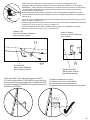
1) Choose BOTTOM or TOP attachment.
2) Locate the through holes in the back of the dresser.
3) Align the hole to be used with the wood wall stud (For Open Bottom Installation, use wood wall stud closest to center)
1) Choisissez une fixation SUPÉRIEURE ou INFÉRIEURE.
2) Repérez les trous percés au dos de la commode.
3) Alignez le trou à utiliser sur le poteau mural en bois (Pour une installation à fond ouvert, utilisez le poteau mural le plus
près du milieu)
1) Seleccione el aditamento SUPERIOR o INFERIOR.
2) Ubique los orificios pasantes en la parte posterior del mueble.
3) Alinee el orificio que utilizará con el pilar de la pared (para una instalación con fondo abierto, utilice el pilar de madera
más cercano al centro)
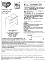
6) Attach the Tip-over restraint strap (ZZ) to the
wall using (1) Long Screw (XX) and (1) washer
(TT) as shown. The screw MUST be installed into
a wood wall stud (See WARNINGS for additional
information).
6) Fixez la sangle du dispositif de
non-renversement (ZZ) au mur à l’aide de (1) vis
longue (XX) et de (1) rondelle (TT) tel qu’illustré.
La vis DOIT être serrez dans un poteau mural en
bois (Pour de plus amples informations, veuillez
vous référer aux AVERTISSEMENTS).
6) Fije la correa de retención contra volcamiento
(ZZ) a la pared utilizando (1) tornillo largo (XX) y
(1) arandela (TT), como se indica. El tornillo
DEBE instalarse en un pilar de madera (para
obtener más información consulte las
ADVERTENCIAS).
ADVERTENCIA
El uso de herramientas de contención
de vuelcos tan solo puede reducir, pero
no eliminar, el riesgo de vuelco.
No intente atornillar a paredes hechas
únicamente de paneles. Debe
atornillar en un pilar u otra estructura
de madera similar, como un zócalo
fijado de manera segura. Si su pared no
tiene vigas de Madera, visite su ferretería o
tienda del ramo más cercana para conseguir un
sistema de anclaje que soporte una fuerza de
tiraje de hasta 50 LBS (22,7 Kgs) para su tipo de
muro. Si no está seguro sobre cómo encontrar
la viga de madera o tiene dudas sobre el tipo de
muro, contacte a un contratista profesional.
5) Drill Ø1/8” hole at Pencil Mark, in
wood wall stud
5) Percez un trou de 1/8 po de
diamètre à l’emplacement de la
marque au crayon, dans le poteau
mural en bois
5) Perfore un orificio de Ø1/8” en la
marca del lápiz, sobre el pilar de
madera
Wood Wall Stud
Poteau mural en bois
Pilar de madera
Pencil Mark
Marque faite au crayon
Marca de lápiz
XX
TT
ZZ
Tipover Restraint
Dispositif de non-renversement
Protección contra volcamiento
WARNING
Use of tip-over restraints may only
reduce, but not eliminate, the risk
of tip-over.
Do not attempt to screw into the
wallboard only. You must screw
into a wood wall stud or other
wood structure such as securely
attached baseboard. If your wall is
not wood stud construction, see your local
hardware store or home center for a wall
anchor system that will hold a pull force of
50 LBS in your wall type. If you are
unsure of how to locate the wood stud, or
of what type of wall you have, contact a
professional contractor.
AVERTISSEMENT
L’utilisation de dispositif anti-renversement
peut uniquement réduire les risques de
renversement, mais ne les élimine pas
totalement.
Ne tentez pas de le visser dans le panneau
de revêtement uniquement. Vous devez
visser dans un poteau mural en bois ou
toute autre structure en bois telle qu’une
plinthe solidement fixée. Si votre mur n'est pas
construit de montants de bois, voyez votre
quincaillerie locale ou centre de rénovation pour une
ancre de mur pouvant supporter 50 livres dans votre
type de mur. Si vous êtes incertain par rapport à
comment localiser le montant ou à quel type de mur
vous avez, contactez un entrepreneur professionnel.
4) Make a pencil mark on the wall using the wood rail as a
guide, pencil mark must be over wood wall stud. Then move
the case away from the wall.
4) Faites une marque sur le mur à l’aide d’un crayon en vous
servant du barre en bois comme guide, la marque au crayon
doit être au-dessus du poteau mural en bois. Ensuite,
déplacez la caisse afin de l’éloigner du mur.
4) Utilizando un lápiz, haga una marca en la pared utilizando
el barra de madera como guía; la marca debe estar sobre el
pilar de madera. Luego, aleje la carcasa de la pared.
34

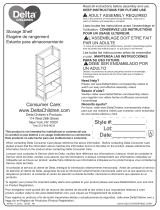
9)Pull case AWAY from wall until Restraint is SNUG.
9) Tirez la caisse afin de L’ÉLOIGNER du mur jusqu’à ce
que le dispositif de non-renversement soit BIEN AJUSTÉ
9) Jale la carcasa ALEJÁNDOLA de la pared hasta que la
retención esté TENSA.
YY
TT
10) Ensure restraint is not loose.
10) Assurez-vous que le dispositif de
non-renversement n’est pas desserré.
10) Asegúrese de que la retención no esté suelta.
Bottom Back Rail
Barre Arrière Inférieur
BarraTraseroInferior
NOTE: Be sure to attach any accessory items to case before completing this step.
7)Feed the Tipover Restarint through the hole as you place the dresser in it’s final position.
REMARQUE : Veillez à fixer tous accessoires sur la caisse avant de l’exécution de cette étape.
7) Faites entrer le dispositif de non-renversement à travers le trou lorsque vous placez la
commode dans s position finale.
NOTA: Asegúrese de fijar todos los accesorios a la carcasa antes de completar este paso.
7) Pase el elemento de retención a través del orificio, a medida que posiciona el mueble en su
posición final.
8) Pull the Tip-over restraint through the hole and fasten it securely to the case using (1) 15mm
screw (YY) and (1) washer (TT).
8) Tirez le dispositif de non-renversement à travers le trou, puis fixez-le solidement sur la caisse
à l’aide de (1) vis de 15 mm (YY) et de (1) rondelle (TT).
8) Pase el elemento de retención a través del orificio y fíjelo con seguridad a la carcasa
utilizando (1) tornillo de 15 mm (YY) y (1) arandela (TT).
Attach to Bottom
Fixez-le à la partir inférieure
Fijar al fondo
Attach to Top
Fixez-le à la partie supérieure
Fijar a la parte superior
YY
TT
Top Back Rail
Barre Arrière Supérieur
Barra Trasero Superior
35
La page est en cours de chargement...
La page est en cours de chargement...
La page est en cours de chargement...
-
 1
1
-
 2
2
-
 3
3
-
 4
4
-
 5
5
-
 6
6
-
 7
7
-
 8
8
-
 9
9
-
 10
10
-
 11
11
-
 12
12
-
 13
13
-
 14
14
-
 15
15
-
 16
16
-
 17
17
-
 18
18
-
 19
19
-
 20
20
-
 21
21
-
 22
22
-
 23
23
-
 24
24
-
 25
25
-
 26
26
-
 27
27
-
 28
28
-
 29
29
-
 30
30
-
 31
31
-
 32
32
-
 33
33
-
 34
34
-
 35
35
-
 36
36
-
 37
37
-
 38
38


Delta Children Essex Changing Table/Bookcase Assembly Instructions
- Taper
- Assembly Instructions
dans d''autres langues
Documents connexes
-
 Delta Children Gateway 2-in-1 Changing Table & Storage Unit Mode d'emploi
-
 Delta Children Happy Home Storage Bookcase Assembly Instructions
-
 Delta Children Eclipse Changing Table Assembly Instructions
-
 Delta Children Gateway 2-in-1 Changing Table & Storage Unit Manuel utilisateur
-
 Delta Children Gateway Ladder Shelf Assembly Instructions
-
 Delta Children Dress Kit Assembly Instructions
-
 Delta Children Fabio Toddler Bed Assembly Instructions
-
 Delta Children Farmhouse 3 Drawer Dresser Assembly Instructions
-
 Delta Children Under Crib Roll-Out Storage Assembly Instructions
-
 Delta Children Emerson 3 Drawer Dresser Manuel utilisateur


