
8016903/ZP97/2017-07-27 • Subject to change without notice • SICK AG • Waldkirch • Germany • www.sick.com TIM35X/TIM36X | SICK 1
TiM35x
TiM36x
Intended use
The TiM35x/TiM36x laser scanner (referred to as the TiM
below) is an intelligent sensor for invisibly detecting objects
in areas (elds) to be monitored. The device is designed for
portable or stationary use indoors or outdoors in standalone
operation, with a scanning range of up to 10 m. The com-
bined control for the four switching inputs activates one of the
16 eld sets for eld monitoring. Each eld set provides three
congurable elds. The TiM indicates detected eld infringe-
ments in relation to the three elds through a combination of
three switching outputs.
The TiM can also evaluate the existence of a contour, which
has to be fully situated within the evaluation eld at all times.
This allows the TiM to detect, for example, that a door opens
outwards or that the position of the TiM has changed. It is
also possible to detect someone crawling beneath a vertical
evaluation eld or a laser beam deected in a mirror.
The TiM is available in both a PNP and an NPN variant. The
NPN variant is identied by S02 in the type code on the type
label.
The purpose of this instruction manual is to allow you to put
the TiM into operation quickly and easily using precongured
eld sets and to obtain the rst detection results.
Further information on the mechanical and electrical
installation is available in the & Technical Information (no.
8014318). This information is available for download on the
TiM product page (www.sick.com/tim3xx).
The TiM is certied to IEC/EN/UL/CSA 61010-1:2007. These
operating instructions may contain passages of text in a
foreign language.
Safety information
• Read these instructions before commissioning the TiM
in order to familiarize yourself with the device and its
functions.
• The TiM corresponds to laser class 1 ( see “Laser radia-
tion!, page 4”).
• Mounting and electrical installation are to be performed
only by qualied technicians.
• Electrical connections between the TiM and other devices
may only be made when there is no power to the system.
Otherwise, the devices may be damaged.
• Wire cross-sections in the supply cable from the custom-
er's power system should be designed in accordance with
the applicable standards. Protect the TiM with an external
0.8 A slow-blow fuse at the beginning of the supply cable.
• All circuits connected to the TiM must be designed as SELV
or PELV circuits. (SELV = Safety Extra Low Voltage, PELV =
Protective Extra Low Voltage).
• Use the device only under permitted environmental
conditions (e.g. temperature, grounding potential, see
“Technical data, page 4”).
• Protect the TiM against moisture and dust when the cover
to the USB socket is open. The black plastic cover must
be screwed ush in order to comply with enclosure rating
IP 67 in operation.
• Turn the swivel connector unit with the electrical connec-
tions max 180° from end position to end position.
• Opening the screws of the TiM housing will invalidate any
warranty claims against SICK AG.
• The TiM does not constitute personal protection equip-
ment in accordance with the respective applicable safety
standards for machines.
Commissioning and conguration
Step 1: Electrical installation
1. Connect the communication interface of the TiM to the
PC (Ethernet or USB; recommended Ethernet, 4-pin M12
female connector).
> If using a USB, connect the TiM's Micro USB port (behind
the black plastic cover on the side) to a free USB port (type
A) on the PC using a suitable shielded high-speed USB
cable (e.g. no. 6036106, 2 m).
The USB cable must not exceed 3 m in length!
When operating the USB interface, be aware that ESD/
EMC inuences may break the USB connection. To re-es-
tablish the data transmission, remove the USB cable on
the TiM and plug it back into the contact. To re-establish
communication between TiM and PC in the SOPAS congu-
ration software, select
CommuniCation > Go online.
2. Turn on and start the PC.
3. Provide power to the TiM (12-pin M12 male connector).
Using the power supply unit it must be ensured that the
supply voltage does not drop below 8 V for longer than
2 ms and never rises above 30 V.
Following successful initialization, the green LED lights up
"
▸" (device ready for operation).
Do not supply the switching inputs with current yet.
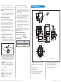
SOPASSOPAS
“Power/I/O”
“USB 2.0”
Configuration
Field monito
ring
Diagnosis
TiM
Connection
box
USBUSB
DC 9 ... 28 V
...
IN 1 IN 4
OUT 1 OUT 3
customer-
provided
OUT 2
OUT 4
delay-
action
fuse
0,8A/T
IN GND
Electrical block diagram for commissioning PNP variant
TiMxS02
IN
9 ... 28 V
SOPASSOPAS
“Power/I/O”
“USB 2.0”
Configuration
Field monitoring
Diagnosis
Connection
box
USBUSB
DC 9 ... 28 V
...
IN 1 IN 4
OUT 1 OUT 3
customer-
provided
OUT 2
OUT 4
delay-
action
fuse
0,8A/T
Electrical block diagram for commissioning NPN variant
Step 2: Mounting and alignment
NOTE
During installation make sure there is no reective surface
behind the reference target see “Device layout, page
3”, point
â.
1. Optional: Mount the TiM to separately ordered mounting
accessories (mounting kit 2), see "Mounting" Chapter in
the & Technical Information (no. 8014318).
2. Otherwise, mount the two straight plates from the
enclosed mounting kit 1 on the TiM using two M3 screws.
Use the two blind-hole threads either on the underside or
back of the housing ( see “Device layout, page 3”). If
the straight plates are not used, screw the screws provided
by the customer max. 2.8 mm into the thread.
3. Mount the TiM on a prepared bracket.
The device should be as free from vibration as possible
during operation.
4. Align the 90° axis of the TiM's scanning angle with the
center of the area to be monitored. The
marking on the
lid of the optical hood serves as a bearing alignment aid
( see “Device layout, page 3”).
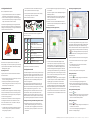
0
Scanning range in m (feet)
Scanning range in m (feet)
0
Scanning range max. 10 m (32.81 feet)
Scanning range typical 8 m (26.25 feet)
for objects up to 10 % remission
180°
‒45°
225°
270°
90°
0°
6
(19.69)
6
(19.69)
2
(6.56)
2
(6.56)
2
(6.56)
2
(6.56)
6
(19.69)
10
(32.81)
14
(45.93)
10
(32.81)
14
(45.93)
6
(19.69)
14
(45.93)
14
(45.93)
10
(32.81)
10
(32.81)
Range diagram for TiM
Detecting Laser Scanner
Short Range
OPERATING INSTRUCTIONS
en

TIM35X/TIM36X | SICK 8016903/ZP97/2017-07-27 • Subject to change without notice • SICK AG • Waldkirch • Germany • www.sick.com2
a. Conguration without PC
Here, the TiM provides two options:
• Using one of 16 default eld sets, each with 3 predened
elds having the same eld shape, but different sizes
• Teach-in of the surrounding contour to automatically gener-
ate the outer eld with any shape, including more complex
shapes, and to deduce the two inner elds.
The eld sets are organized by groups into segmented eld
shapes. The shapes can be modied, with the default being a
rectangle. In the factory setting, the 3 origin-oriented elds of
a set are nested inside one another.
Segmented,
free shape type
Rectangle
Field 1
Field 2
Field 3
0°180°
90°
Structure of the elds of a eld set and possible eld shapes
Dimensions of the respective eld 1 and its shape in the
factory settings, as well as the required wiring of the switching
inputs for eld set selection see “Field set factory settings
– switching inputs, page 4”.
Preparing for teach-in
In general, the function button and both LEDs on the device
are used for teach-in.
• Remove all objects that will not permanently be in the eld
of view in monitoring mode later on.
• Distance yourself sufciently from the TiM during the
advance warning phase of the teach-in, so that you are not
detected as part of the eld contour.
Teaching-in the eld contour
The TiM uses eld set 1 (segmented, initial shape: rectangle)
to adjust the eld shape and size to the surrounding contour
that was detected. The switching inputs may not be supplied
with current during this process.
The TiM forms the outer eld 3 from the surrounding contour
with a negative offset of 100 mm, and deduces the limits
of the two inner elds from this, so that eld 2 = eld 1 plus
25% and eld 3 = eld 1 plus 52%.
• The eld shape to be formed can be dened by pacing out
the limits during the teach-in phase. Do not wear black
clothing during this process!
• The TiM stores the shortest value measured during the
teach-in phase as a eld limit for each angle.
• Note: A parameter upload is required in order to display
the newly taught-in eld contour in SOPAS.
> Start the eld contour teach-in.
3 seconds
= flashes slowly
The behavior of the two LEDs indicates the progress of the
eld contour teach-in:
LED a
(red)
LED b
(green)
Status
–
Field contour teach-in – Start
LED ashes slowly (0.5 Hz)
Field contour teach-in – Advance warning
phase
LED ashes increasingly rapidly within 15 s
O O
Field contour teach-in – Teach-in phase
60 seconds
–
Field contour teach-in – Completion of
advance warning phase
LED ashes increasingly rapidly within 15 s
–
O
Automatic return to monitoring mode
All elds free
O O
Monitoring mode
In the event of eld infringement
O = illuminated, = ashing
The TiM stores the new eld set 1 permanently.
b. Conguration with PC
The SOPAS conguration software is used by default to adjust
the 3 elds of a eld set and other TiM parameters to the ap-
plication and to perform diagnostics in the event of an error.
If the eld shape of the eld set 1 has been taught in without
a PC using the function button, SOPAS is generally used to
continue the conguration.
This includes setting the eld shapes/sizes and any other
non-teachable eld sets based on the default setting, the
response time of the elds, the blanking size, and the holding
time of the assigned switching outputs OUT 1 ... OUT 3.
The blanking size is the smallest size from which an object
can be detected in a eld by the TiM and lead to a eld
infringement. All objects that are smaller than the minimum
size are blanked out. Like the response time and the holding
time, the blanking size applies to all eld sets and their elds.
Installing and launching the SOPAS conguration software
1. Download and install on the PC the software from the
website "www.sick.com/SOPAS_ET“. In this case, select
the "Complete" option as suggested by the install wizard.
Administrator rights may be required on the PC to install
the software.
2. Start the "Single Device" program option after completing
the installation.
Path: Start > Programs > SICK > SOPAS Engineering Tool >
SOPAS (Single Device).
SOPAS will automatically install the necessary USB driver
the rst time it detects a connected TiM. It may then be
necessary to restart the PC.
3. Establish a connection between SOPAS and TiM via the
wizard which opens automatically. Select the TiM from the
list of available devices.
SOPAS program window (single device)
Field monitor display window
• In the Field monitor window, SOPAS displays the eld
contour (scan line) currently seen by the device through
ambient reection in blue. If the 4 switching inputs are
not supplied with current, SOPAS also displays the three
evaluation elds (segmented rectangles) for the eld set
1 according to the TiM's default setting, or the eld shape
generated using the teach-in function along with its dimen-
sions, the status of the switching inputs/outputs, and the
position of the mouse pointer.
• SOPAS displays the elds as green if no eld infringement
is present. If objects of a certain size ( see “Default set-
tings TiM, page 3”) are located for a certain duration
in the part of the visual range that is covered by elds,
the TiM will recognize this as a eld infringement. SOPAS
displays this separately in yellow for the individual elds.
> Try changing the orientation of the TiM in the room and ob-
serve the effects this has on detection in the eld monitor.
Click the
reset button to cause SOPAS to reset the switch-
ing output counters.
Continuing the conguration process
Field editor display window
The user can change parameters in the right part of the pro-
gram window under
settinGs & deviCe status. SOPAS immedi-
ately transfers these changes to the TiM (default setting).
However, evaluation elds that have been changed in size and
shape must always be manually transferred to the TiM using
the
button. All changed parameters are only temporarily
stored in the device for the time being and are not stored in
the computer at all.
In order to optimize the dimensions of the monitoring elds:
1. Click the
evaluation Fields tab at the top of the program
window.
2. Under
Field seleCtion on the right side of the window,
select, for example, eld set 1.
3. Select the eld to be congured.
> You can optionally perform the following actions:
Shifting eld positions
1. Click the
button.
2. Click on the green marking rectangle of the desired eld
position in the outer eld.
The color of the marking rectangle changes to blue.
3. Re-click the rectangle and drag it to the desired position,
then release the pushbutton. SOPAS controls the available
positioning area during shifting.
Inserting additional eld positions
1. Click the
button.
2. Click on the desired position on the limits of the outer eld.
SOPAS inserts a new, green marking rectangle. This can
now also be shifted as already described.
Deleting eld positions
1. Click the
button.
2. Click on the green marking rectangle of the eld position to
be deleted in the outer eld.
The color of the marking rectangle changes to red.
3. Re-click the marking rectangle.

8016903/ZP97/2017-07-27 • Subject to change without notice • SICK AG • Waldkirch • Germany • www.sick.com TIM35X/TIM36X | SICK 3
SOPAS removes the marking rectangle and instead con-
nects the two nearest marking rectangles with a new line.
Rotating the eld pair around the central axis along with
the TiM
> In order to align the position of the eld pair in SOPAS to
the conditions on site from the user's perspective, enter
and conrm the desired angle of rotation in the 0.0° input
eld (negative sign "
–" means turn right).
Setting up the reference contour eld
In each eld set, any eld can be selected as a reference
contour eld. The reference contour eld is used to monitor
contours. This makes it possible to recognize when the
background is no longer detected in the required eld – for
example, as a result of covering or rotating the sensor.
The TiM uses the same evaluation strategy for all reference
contour elds (evaluation time and blanking size).
1. Select the required eld in the eld set.
2. Select the
reFerenCe Contour Field check mark under Field
seleCtion.
3. Delete the two eld positions closest to the sensor.
4. Mark the two remaining eld positions and shift them
outside of the required reference contour area.
5. Use the
button to switch to the conguration for the
reference contour eld start points. The eld starting
points must lie between the scan line and the scanner so
that the scan line passes between the start and end points
of the reference contour eld.
Cont
our as reference field
Field start point
TiM
Field end point
Scan line
6. Depending on the required shape of the reference contour
eld, create additional eld points between the sensor and
the reference contour eld. The distance between the start
and end points of the reference contour eld should be
approximately 20 cm.
> The
button can be used to switch between the start
and end points of the reference contour eld for editing
purposes. The active points are highlighted in light green
while the deactivated points are dark green.
Some other useful functions
•
button: Display the elds in the polar coordinate
system
•
button: Change the view of the TiM/ elds from above
(TiM: black) to the view from below (TiM: blue)
•
or button: Switch off the display the full measur-
ing line or display a dotted measuring line.
Response time, blanking size and holding time
> Adjust the response time of the elds, the blanking size
of objects, and the holding time of the OUT 1 and OUT 4
switching outputs under
settinGs on the right side of the
program window. All three values are valid for both elds
and switching outputs.
When selecting the response time, note that the TiM's
internal reaction time must also be added (max. 67 ms).
> To test the effects of the changed settings, click on the
Field evaluation monitor tab at the top.
If the changed elds have been transferred to the TiM as
described, SOPAS will also display these in the monitor,
displaying the infringed elds in yellow. If you wish to
observe another eld set, it must rst be activated accord-
ingly using the switching inputs. If you wish to observe
another eld set, it must rst be activated accordingly
using the switching inputs.
The blanking size is the cross-section of the object after
which an object not previously in the viewing area of the TiM
leads to a eld infringement.
Completing the conguration process
> Permanently save the entire conguration:
Parameter set in: TiM click the
button
Conguration le on the PC: click the
button.
Default settings TiM
Parameter Value
Blanking size Cross-section 200 mm
Response time of the elds 335 ms (5 scans)
Holding time of the switching outputs 335 ms (5 scans)
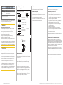
Description of the device
Device layout
4
5
3
ß
7
All dimensions in mm (inch)
9
à
22
225°‒45°
180°0°
ä
ã
85.75 (3.38)
27.3
[24.4
62.46
(2.46)
60 (2.30)
0.7 (0.03)
[68.8 (2.71)]
[76.25
(3.00)]
61
(2.40)
46.71 (1.84)
74.39 (2.93)
101.12 (3.98)
17.37
(0.68)
51 (2.01)
30°
90°
6
á
8
â
2
1
Mounting set 1
2 x
51
(2.01)
44.79 (1.76)
16.79
(0.66)
33 (1.3)
[Ø 4.3
(0.17)
]
(0.96)]
(1.07)
8
(0.31)
24.4
(0.96)
1 2 x straight plates with M3 x 4 mm screw (included in scope of
delivery)
2 M3 threaded mounting hole, 2.8 mm deep (blind hole thread)
3 Optical hood
4 Receiving range (light inlet)
5 Transmission range (light emission)
6 Function button for teach-in
7 Red and green LED (status displays)
8 Swivel connector unit with electrical connections and á
9 Micro USB port, behind the black plastic cover
('Aux interface' connection for conguration with PC)
"Power/inputs and outputs" connection, 12-pin M12 male connector
à Marking for the position of the light emission level
á Ethernet connection, 4-pin M12 female connector
â Area in which no reective surfaces are allowed for mounted devices
ã Bearing marking to support alignment (90° axis)
ä 270° aperture angle (visual range)

8016903/ZP97/2017-07-27 • Subject to change without notice • SICK AG • Waldkirch • Germany • www.sick.com TIM35X/TIM36X | SICK 4
a CAUTION
Laser radiation!
CLASS 1 LASER PRODUCT
The TiM corresponds to laser class 1 (eye-safe).
The laser beam is not visible to the human eye.
CAUTION – the use of controls, or adjustments or perfor-
mance of procedures other than those specied herein may
result in hazardous radiation exposure.
> Do not open the housing (opening the housing will not
switch off the laser).
> Pay attention to the laser safety regulations as per
IEC 60825-1 (latest version).
a MISE EN GARDE
Rayonnement laser !
APPAREIL À LASER DE CLASSE 1
Le TiM est conforme à la classe laser 1 (sécurité des yeux).
Le rayon laser n’est pas visible pour l’oeil humain.
PRUDENCE – tout usage de commandes, réglages ou toute
application de procédures autres que ceux décrits dans ce
document peut entraîner une exposition dangereuse au
rayonnement.
Attention – L’utilisation des commandes ou réglages ou l’ex-
écution des procédures autres que celles spéciées dans les
présentes exigences peuvent être la cause d’une exposition à
un rayonnement dangereux.
> Ne pas ouvrir le boîtier. (La diode laser n’est pas désac-
tivée en cas d’ouverture du boîtier)
> Se conformer aux dernières consignes de protection en
date contre le rayonnement laser IEC 60825-1 (dernière
version).
Additional information see “Technical data, page 4”.
Status indicators, functions
Status displays
LED a
(red)
LED b
(green)
Status
–
O
Device ready/monitoring mode
O O
Field infringement
–
Teach-in – Start
O O
Teach-in – End of advance warning phase
60-second teach-in phase
–
Teach-in – End of teach-in phase
–
Errors
– –
Device without supply voltage
O = illuminated; = ashing
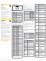
Field set factory settings – switching inputs
Field
set
Switching inputs Field shape
Default size of eld 1
IN 1 IN 2 IN 3 IN 4
1 0 0 0 0
Rectangle
1)
, segmented
L: 1 m, W: 2 m
2 1 0 0 0
Rectangle
1)
, segmented
L: 1.25 m, B: 2 m
3 0 1 0 0
Rectangle
1)
, segmented
L: 1.5 m, B: 2 m
4 1 1 0 0
Rectangle
1)
, segmented
L: 1.75 m, B: 2 m
5 0 0 1 0
Rectangle
1)
, segmented
L: 1 m, W: 2 m
6 1 0 1 0
Rectangle
1)
, segmented
L: 1.25 m, B: 2 m
7 0 1 1 0
Rectangle
1)
, segmented
L: 1.5 m, B: 2 m
8 1 1 1 0
Rectangle
1)
, segmented
L: 1.75 m, B: 2 m
9 0 0 0 1
Rectangle
1)
, segmented
L: 1 m, W: 2 m
10 1 0 0 1
Rectangle
1)
, segmented
L: 1.25 m, B: 2 m
11 0 1 0 1
Rectangle
1)2)
, segmented
L: 1.5 m, B: 2 m
12 1 1 0 1
Rectangle
1)
, segmented
L: 1.75 m, B: 2 m
13 0 0 1 1
Rectangle
1)
, segmented
L: 1 m, W: 2 m
14 1 0 1 1
Rectangle
1)
, segmented
L: 1.25 m, B: 2 m
15 0 1 1 1
Rectangle
1)
, segmented
L: 1.5 m, B: 2 m
16 1 1 1 1
Rectangle
1)
, segmented
L: 1.75 m, B: 2 m
L = length, W = width
1) Default setting, starting shape can be modied as required
Input level
• PNP: Low (in resting position): ≤ 2 V, high (in working
position): ≥ 8 V
• NPN: Active low (in working position): ≤ (IN 9...28 V) – 8 V,
inactive high (in resting position) > (IN 9...28 V) – 2 V
Assignment of infringed elds - switching outputs
Fields of a eld set Switching outputs
OUT 1 OUT 2 OUT 3
Fields 1, 2, and 3 infringed Active
Active Active
Fields 2 and 3 infringed
Deacti-
vated
Active Active
Field 3 infringed
Deacti-
vated
Deacti-
vated
Active
All elds free
Deacti-
vated
Deacti-
vated
Deacti-
vated
Field 1: inner, eld 2: center, eld 3: outer
Active: in working position; deactivated: in resting position
Output level
• PNP: The level of the switching outputs OUT 1 ... OUT 3 is
active low (in resting position: high, in working position: low
(eld infringed)).
• NPN: The level of the switching outputs OUT 1 ... OUT 3 is
active high (in resting position: low, in working position:
high (eld infringed)).
All elds of a eld set are also deemed to be infringed during
switching on, booting, in the event of an error, and when the
device is switched off.
The OUT 4 switching output works with the following levels:
Function Level PNP Level NPN
Device Ready High Low
Index signal (15 Hz), corresponds to
measurement at 90°
Low-Peaks High-Peaks
Errors Low High
Technical data
Model name TiM351-2134001 (Part no. 1067299)
TIM361-2134101 (Part no. 1071399)
Scanning range
Radial, aperture angle 270°
Angular resolution
TiM35x: 1°
TiM36x: 0.33°
Scanning fre-
quency
15 Hz (15 scans/s)
Response time
Typical 67 ms (1 scan)
Scanning range
0.05 m to 10 m; typically 8 m at 10%
remission
1)
Remission
Typical 4% ... > 1,000% (reector)
Physical Minimum
object size
(cross-section)
213 mm (TiM35x) / 121 mm (TiM36x) for a
scanning range of 8 m,
112 mm (TiM35x) / 66 mm (TiM36x) for a
scanning range of 4 m,
61 mm (TiM35x) / 38 mm (TiM36x) for a
scanning range of 2 m and 10% remission
Measuring error
Statistical (1 s): ± 20 mm
Systematic: ± 60 mm
Temperature drift 0.5 mm/K
Model name TiM351-2134001 (Part no. 1067299)
TIM361-2134101 (Part no. 1071399)
Ambient light
immunity
80,000 lx (indirect)
Light source
Laser diode, infrared (λ = 850 nm)
Device laser class
Laser class 1 according to EN 60825-1:
2014
2)
, eye-safe
Max. radiated
power
2.0 W (TIM35x)
1.5 W (TIM36x)
Max. pulse
duration
5 ns
Field evaluation
1 evaluation mode with 1 eld set (up to 3
detection elds), optional separate evaluation
for 1 reference contour eld
Field infringement signaling via a combination
of 3 switching outputs.
Number of eld
sets
16, each with 3 exible, congurable elds,
one of which can be used as a reference
contour eld
Aux interface
USB 2.0 for conguration, connecting cable
max. 3 m.
Ethernet interface Max. data rate: 10 Mbit and 100 Mbit, cable
length limited to max. 100 m
Switching inputs PNP: 4 x IN (U
e
= max. 28 V, I
e
= max. 5 mA),
opto-decoupled, debouncing time approx.
10 ms
NPN: Common reference potential 9 ... 28 V
Switching outputs 4 x OUT (each I
a
≤ 100 mA), not galvanically
isolated from the supply voltage, short-circuit
protected/temperature protected
Congurable for OUT 1 .... OUT 3:
Response time (67 ms ... 30 s)
Holding time (0 ms ... 10 s)
3)
Electrical connec-
tions
1 x 12-pin M12 power male connector
1 x 4-pin. M12 Ethernet socket
1 x micro USB socket, type B (covered)
Function key Teach-in (eld set 1 eld contour)
Optical indicators 2 x LED
Supply voltage DC 9 ... 28 V, SELV an PELV acc. to
IEC 60364-4-41: 2005-12
Power consump-
tion
4 W (with switching outputs without load)
16 W (with four loaded switching outputs)
Housing Lower part: Die-cast aluminum
Optics hood: Polycarbonate with scratch-proof
coating
Weight
Approx. 250 g without cables
Electrical safety
According to According to IEC 61010-1 (ed.3)
Protection class
III according to EN 61140: 2006-08
IEC 61010-1 (ed.3)
Enclosure rating
IP 67 (EN 60529: 1991-10/A2: 2000-02)
No specied enclosure rating for opened
"Aux interface" connection and/or plugged in
USB cable!
EMC
Radiated emission: Residential area according
to EN 61000-6-3: 2007-01
Electromagnetic immunity: Industrial environ-
ment according to
EN 61000-6-2: 2005-08
Vibration resis-
tance
According to EN 60068-2-6: 2008-02
Shock resistance
According to EN 60068-2-27: 2009-05
Ambient tempera-
ture
Commissioning/switching on: –10 ... +50 °C
Operation: –25 °C to +50 °C
Storage: –40 °C to +75 °C
Temperature
change
According to EN 60068-2-14: 2009-07

TIM35X/TIM36X | SICK 8016903/ZP97/2017-07-27 • Subject to change without notice • SICK AG • Waldkirch • Germany • www.sick.com5
Model name TiM351-2134001 (Part no. 1067299)
TIM361-2134101 (Part no. 1071399)
Damp heat
According to EN 60068-2-30: 2005-12
Air humidity
< 80%
Installation height
< 5,000 m above sea level
Ambient condi-
tions
According to EN 61010-1:2011-07, contamina-
tion level 3 outside housing
1) T < -15 °C: typ. 7.5 m at 10% Remission
2) Complies with 21 CFR 1040.10 and 1014.11 except for the deviations pursu-
ant to Laser Notice No. 50 of June 2007
3) The TiM has an internal, system-related delay time of 67 ms.
For further technical specications, see the Online data sheet
on the product website (www.sick.com/tim3xx).
a WARNING
Risk of potential equalization currents
The TiM is designed to be operated in a system with proper
grounding of all connected devices and mounting surfaces
to the same ground potential. If this condition is not met,
potential equalization currents may through along the cable
shields, causing the following hazards:
• Dangerous contact voltage on the metal housing
• Malfunction or destruction of the TiM
• Heating of the cables with possible spontaneous combus-
tion.
> See the "Electrical installation“ chapter in the & Technical
Information (no. 8014318) on the product site on the web
(www.sick.com/tim3xx) for measures to eliminate hazards.
a ATTENTION
Risques liés à des courants d’équipotentialité
Le TiM a été conçu pour être utilisé dans une installation
prévoyant une mise à la terre correcte de tous les appareils
et surfaces de montage raccordés sur un même potentiel de
sol. Si cette condition n’est pas remplie, des courants d’équi-
potentialité risquent dans certaines conditions de passer par
les blindages des câbles et d’exposer aux risques suivants :
• tension de contact dangereuse sur le boitier en métal,
• comportement incorrect ou destruction du TiM.
• chauffe des câbles jusqu’à leur inammation spontanée.
> Pour des mesures de prévention de tels risques, voir le
chapitre « Installation électrique » de & l’Information tech-
nique (no. 8014318) ou sur la page produit sur internet
(www.mysick.com/en/tim3xx).
Pin assignment for rotary corners
Connection plug pin positions
“Power/switching inputs/outputs” connection
12-pin M12 plug on the cable
IN 4 (switching input)
IN 3 (switching input)
IN 1 (switching input)
IN 2 (switching input)
DC 9 ... 28 V
GND
n.c.
OUT 1 (switching output)
OUT 2 (switching output)
7
6
OUT 4 (switching output)
OUT 3 (switching output)
4
3
2
1
5
8
9
10
11
12
4
10
1112
8
6
7
9
1
5
3
2
PNP: INGND
NPN: IN 9 ... 28 V (Reference potential for
switching inputs)
Ethernet connection (6034415)
4
3
2
1
TD+
TD–
RD+
RD–
4
32
1
“Ethernet” connection
M12 socket,
D-encoded
Maintenance and care
The TiM does not contain any components that require main-
tenance. Maintenance is not necessary to ensure compliance
with laser class 1.
> If it is dirty, carefully clean the infrared light-permeable,
black optical hood to ensure optimal detection perfor-
mance. Use a soft, damp cloth and a mild cleaning agent.
Transport and storage
The TiM must be transported and stored in its original pa-
ckaging with the USB protective cap plugged in. Do not store
outdoors. To ensure that any residual moisture present can
escape. Do not expose to aggressive media (e. g., solvents).
Storage conditions: dry, dust-free, no direct sunlight, as little
vibration as possible, storage temperature –40°C to +75°C,
relative air humidity max. 90% (non-condensing).
Repair
Repair work on TiM35x may only be performed by qualied
and authorized service personnel from SICK AG.
Removal and disposal
Any TiM35x which can no longer be used at the end of the
product life cycle must be disposed of in an environmentally
friendly manner in accordance with the respective applicable
country-specic waste disposal regulations.
The TiM35x is electronic waste and must under no circum-
stances be disposed of with general waste!
Sources for obtaining additional informat
Additional information about the TiM and its optional acces-
sories can be found in the following places:
Product web page for the TiM3xx
(www.sick.com/tim3xx)
• Technical Information (supplementary information on
mounting and electrical installation, an overview list, and
license texts for open-source software) in German (no.
8014317) and English (no. 8014318).
• These operating instructions in German (no. 8016902),
English (no. 8016903), and in other languages if required
• SOPAS conguration software with online help
• Ordering information in the detection and ranging solu-
tions product catalog
• TiM3xx product information
• Detailed technical specications (online data sheet)
• Dimensional drawing and 3D CAD dimension models in
various electronic formats
• EC declaration of conformity
• SOPAS conguration software updates
Support is also available from your sales partner: www.sick.
com/worldwide.
Copyright notices for open-source programs
SICK uses open source software in its TiM sensors. This
software is licensed by the rights holders using the following
licenses among others: the free licenses GNU General Public
License (GPL Version2, GPL Version3) and GNU Lesser Gen-
eral Public License (LGPL), the MIT license, zLib license, and
the licenses derived from the BSD license.
This Program is distributed in the hope that it will be useful,
but WITHOUT ANY WARRANTY; without even the implied war-
ranty for merchantability or tness for a particular purpose.
See the GNU General Public License for more details.
View the complete license texts here: www.sick.com/licen-
setexts.
A printed copy of the license texts is also available on request.

8016903/ZP97/2017-07-27 • Subject to change without notice • SICK AG • Waldkirch • Germany • www.sick.com TIM35X/TIM36X | SICK 6
8016903/ZP97/2017-07-27 ∙ 8M_DR ∙ Printed in Germany (2017-07) ∙ All rights reserved ∙ Subject to change without notice
-
 1
1
-
 2
2
-
 3
3
-
 4
4
-
 5
5
-
 6
6


