KitchenAid KOSE500EBS04 Guide d'installation
- Taper
- Guide d'installation

INSTALLATIONINSTRUCTIONS
27" (68.6 CM) AND 30" (76.2 CM) ELECTRIC
SINGLEAND DOUBLEBUILT-INOVEN
INSTRUCTIONSD'INSTALLATION
FOURELECTRIQUEENCASTRE27" (68,6 CM) ET30"
(76,2 CM) - SIMPLEETDOUBLE
TableofContents/Table des mati@res
BUILT-IN OVEN SAFETY ............................................................... 2
INSTALLATION REQUIREMENTS ................................................ 2
Tools and Parts ............................................................................ 2
Location Requirements ................................................................ 3
Electrical Requirements ............................................................... 6
INSTALLATION INSTRUCTIONS .................................................. 7
Prepare Built-In Oven ................................................................... 7
Remove Oven Door(s) .................................................................. 7
Replace Oven Door(s) .................................................................. 7
Positioning Oven Feet for Multiple Cabinet Cutout Heights .......8
Make Electrical Connection ....................................................... 13
Install Oven ................................................................................. 14
Install Warming Drawer Deflector Kit (Only for Ovens Installed
Above Warming Drawers) .......................................................... 15
Complete Installation ................................................................. 16
SI_CURITI_ DU FOUR ENCASTRI_ .............................................. 17
EXIGENCES D'INSTALLATION ................................................... 17
Outillage et pieces ...................................................................... 17
Exigences d'emplacement ......................................................... 18
Specifications electriques .......................................................... 21
INSTRUCTIONS D'INSTALLATION ............................................. 22
Preparation du four encastre ..................................................... 22
Depose de la/des porte(s) du four ............................................. 22
Reinstallation de la/des porte(s) du four .................................... 23
Positionnement des pieds du four pour des ouvertures
d'encastrement de hauteur differente ........................................ 24
Raccordement electrique ........................................................... 28
Installation du four ...................................................................... 29
Installation de I'ensemble de deflecteur du tiroir-rechaud
(uniquement pour les fours installes au-dessus d'un tiroir-
rechaud) ...................................................................................... 31
Achever I'installation .................................................................. 32
iMPORTANT:
Save for local electrical inspector's use.
iMPORTANT :
,&,conserver pour consultation par I'inspecteur local des installations 61ectriques.
W10725670B

BUILT-INOVEN SAFETY
Your safety and the safety of others are very important.
We have provided many important safety messages in this manual and on your appliance. Always read and obey all safety
messages.
This is the safety alert symbol.
This symbol alerts you to potential hazards that can kill or hurt you and others.
All safety messages will follow the safety alert symbol and either the word "DANGER" or "WARNING."
These words mean:
You can be killed or seriously injured if you don't immediately
follow instructions.
You can be killed or seriously injured if you don't follow
instructions.
All safety messages will tell you what the potential hazard is, tell you how to reduce the chance of injury, and tell you what can
happen if the instructions are not followed.
INSTALLATIONREQUIREMENTS
Gather the required tools and parts before starting installation.
Read and follow the instructions provided with any tools listed
here.
Tools Needed
• Phillips screwdriver
• Measuring tape
• Hand or electric drill (for wall cabinet installations)
• 1" (2.5 cm) drill bit (for wall cabinet installations)
• Level
• Flat-blade screwdriver
Parts Needed
UL listed or CSA approved conduit connector
UL listed wire connectors
Warming Drawer Deflector Kit (for ovens installed above a
warming drawer)
Order Part Number W10510613 for white 27" (68.6 cm) kit
Order Part Number W10531009 for black 27" (68.6 cm) kit
Order Part Number W10536338 for stainless steel 27"
(68.6 cm) kit
Order Part Number W10510614 for white 30" (76.2 cm) kit
Order Part Number W10531010 for black 30" (76.2 cm) kit
Order Part Number W10536339 for stainless steel 30"
(76.2 cm) kit
Order Part Number W10727416A for stainless steel/black 30"
(76.2 cm) kit
To order, see the "Assistance or Service" section of the Use
and Care Guide.
Flush Installation Kit (for Single and Double installed at flush
installation)
Order Part Number W10752684A for white 27" (68.6 cm) kit
Order Part Number W10752685A for black 27" (68.6 cm) kit
Order Part Number W10752686A for stainless steel 27"
(68.6 cm) kit
Order Part Number W10752680A for white 30" (76.2 cm) kit
Order Part Number W10752681A for black 30" (76.2 cm) kit
Order Part Number W10752683A for stainless steel 30"
(76.2 cm) kit
Order Part Number W10752682A for blacWstainless steel 30"
(76.2 cm) kit
To order, see the "Assistance or Service" section of the Use
and Care Guide.
Parts Supplied
• #8-14 x 1" screws - single ovens (2), double ovens (4)
• #8-18 x 3/8"screws - bottom vent (2)
• #8-18 x 1/4"screws - bottom vent trim (4)
• #8-18 x 3/8"screws - double oven feet (4)
• Bottom vent
• Bottom vent trim
• Rear feet- double oven (2)
• Front feet- double oven (2)
• Foam strip- single oven*
Check local codes. Check existing electrical supply. See
"Electrical Requirements."
It is recommended that all electrical connections be made by a
licensed, qualified electrical installer.
*Foam strip not included with double oven.
2

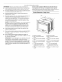
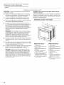
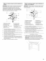
IMPORTANT." Observe all governing codes and ordinances.
• Cabinet opening dimensions that are shown must be used.
Given dimensions provide minimum clearance with oven.
• Recessed installation area must provide complete enclosure
around the recessed portion of the oven.
• Grounded electrical supply is required. See "Electrical
Requirements" section.
• Electrical supply junction box should be located 3" (7.6 cm)
maximum below the support surface when the oven is
installed in a wall cabinet. A 1" (2.5 cm) minimum diameter
hole should have been drilled in the right rear or left rear
corner of the support surface to pass the appliance cable
through to the junction box.
NOTE: For undercounter installation, it is recommended that
the junction box be located in the adjacent right or left
cabinet. If you are installing the junction box on rear wall A
behind oven, it is recommended that the junction box be
recessed and located in the upper center of the cabinet.
• Oven support surface must be solid, level and flush with
bottom of cabinet cutout.
Floor must be able to support a single oven weight of 129 Ibs
(59 kg) for 27" (68.6 cm) models or 154 Ibs (70 kg) for 30"
(76.2 cm) models.
Floor must be able to support a double oven weight of
251 Ibs (114 kg) for 27" (68.6 cm) models or 288 Ibs (131 kg)
for 30" (76.2 cm) models.
IMPORTANT: To avoid damage to your cabinets, check with
your builder or cabinet supplier to make sure that the
materials used will not discolor, delaminate or sustain other
damage. This oven has been designed in accordance with
the requirements of UL and CSA International and complies
with the maximum allowable wood cabinet temperatures of
194°F (90°C).
Undercounter Installation (With Cooktop Installed Above):
Ovens approved for this type of installation have an approval
label located on the top of the oven. Refer to Cutout Dimensions
For Ovens Installed Under Cooktop (separate sheet).
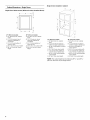
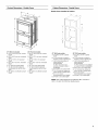
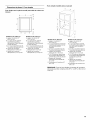
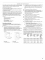
Product Dimensions - Single Ovens
B
D
27" (68.6 cm) models
A. 28_/4''(72.8 cm) max. overall
height
B. 25 z_,, (64.6 cm) max. recessed
width
C. 26 _" (67.9 cm) recessed height
D. 23 ¼" (59.1 cm) max. recessed
depth
E. 27" (68.6 cm) overall width
F. 12" (30.5 cm) from back of
control panel to start of strain
relief
G. 48" (121.9 cm) flexible conduit
length
30" (76.2 cm) models
A. 28_/4" (72.8 cm) max. overall
height
B. 28 z_ '' (72.2 cm) max. recessed
width
C. 26_" (67.9 cm) recessed height
D. 23 ¼" (59.1 cm) max. recessed
depth
E.30" (76.2 cm) overall width
F. 12" (30.5 cm) from back of
control panel to start of strain
relief
G. 48" (121.9 cm) flexible conduit
length

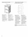
Cabinet Dimensions - Single Ovens
Single Oven Undercounter (Without Cooktop Installed Above)
A B
E
27" (68.6 cm) models
A. 27" (68.6 cm) min. cabinet
width
B. 1½" (3.8 cm) min. top of
cutout to underside of
cou ntertop
C. 5¼" (13.3 cm) bottom of
cutout to floor
D. 25½" (64.8 cm) cutout width
E. 28" (71.2 cm) min. cutout
height
30" (76.2 cm) models
A. 30" (76.2 cm) min. cabinet
width
B. 1½" (3.8 cm) min. top of
cutout to underside of
countertop
C. 5¼" (13.3 cm) bottom of
cutout to floor
D. 28 ½" (72.4 cm) cutout width
E. 28" (71.2 cm) min. cutout
height
Single Ovens Installed in Cabinet
F
B
E
27" (68.6 cm) models
A. 27" (68.6 cm) min. cabinet
width
B. 1" (2.5 cm) top of cutout to
bottom of upper cabinet door
C. 32" (81.3 cm) bottom of cutout
to floor
D. 25½" (64.8 cm) cutout width
E. 1½" (3.8 cm) min. bottom of
cutout to top of cabinet door
E 28" (71.2 cm)* recommended
cutout height
G. 24" (60.7 cm) cutout depth
30" (76.2 cm) models
A. 30" (76.2 cm) min. cabinet
width
B. 1" (2.5 cm) top of cutout to
bottom of upper cabinet door
C. 32" (81.3 cm) bottom of
cutout to floor
D. 28 ½" (72.4 cm) cutout width
E. 1½" (3.8 cm) min. bottom of
cutout to top of cabinet door
F. 28" (71.2 cm)* recommended
cutout height
G. 24" (60. 7 cm) cutout depth
*NOTE: The cutout height can be between 261%e'' and 297/le''
(68.4 cm and 74.8 cm) for single ovens.

Product Dimensions - Double Ovens
B
Cabinet Dimensions - Double Ovens
Double Ovens Installedin Cabinet
A
F
B
E
27" (68.6 cm) models
A. 51 _" (130.0 cm) max. overall
height
B. 25 z_ '' (64.6 cm) max. recessed
width
C. 481_,, (124.0 cm) recessed
height
D. 23 ¼" (59.1 cm) max. recessed
depth
E.27" (68.6 cm) overafl width
F. 12" (30.5 cm) from back of
control panel to start of strain
relief
G. 66" (167.6 cm) flexible conduit
length
30" (76.2 cm) models
A. 51 _" (130.0 cm) max. overall
height
B. 28 z_,, (72.2 cm) max. recessed
width
C. 48 _" (124.0 cm) recessed
height
D. 23 ¼" (59.1 cm) max. recessed
depth
E. 30" (76.2 cm) overall width
F. 12" (30.5 cm) from back of
control panel to start of strain
relief
G. 66" (167.6 cm) flexible conduit
length
27" (68.6 cm) models
A. 27" (68.6 cm) min. cabinet
width
B. 1" (2.5 cm) top of cutout to
bottom of upper cabinet door
C. 14_" (37.5 cm) bottom of
cutout to floor is
recommended.
4"-14_" (10.2-37.5 cm)
bottom of cutout to floor is
acceptable.
D. 25 ½" (64.8 cm) cutout width
E. 1½" (3.8 cm) min. bottom of
cutout to top of cabinet door
F. 50¼" (127.6cm)*
recommended cutout height
G. 24" (60.7 cm) cutout depth
C
30" (76.2 cm) models
A. 30" (76.2 cm) min. cabinet
width
B. 1" (2.5 cm) top of cutout to
bottom of upper cabinet door
C. 14_" (37.5 cm) bottom of
cutout to floor is
recommended.
4"-14_" (10.2-37.5 cm) bottom
of cutout to floor is acceptable.
D. 28½" (72.4 cm) cutout width
E. 1½" (3.8 cm) min. bottom of
cutout to top of cabinet door
F. 50¼" (127.6 cm)*
recommended cutout height
G. 24" (60.7 cm) cutout depth
*NOTE: The cutout height can be between 487/8"and 523/le''
(124.1 cm and 132.6 cm) for double ovens.

Ifcodespermitandaseparategroundwireisused,itis
recommendedthataqualifiedelectricalinstallerdeterminethat
thegroundpathandthewiregaugeareinaccordancewithlocal
codes.
Checkwithaqualifiedelectricalinstallerifyouarenotsurethe
ovenisproperlygrounded.
Thisovenmustbeconnectedtoagroundedmetal,permanent
wiringsystem.
Besurethattheelectricalconnectionandwiresizeareadequate
andinconformancewiththeNationalElectricalCode,ANSI/
NFPA70-latesteditionorCSAStandardsC22.1-94,Canadian
ElectricalCode,Part1andC22.2No.O-M91-1atestedition,and
alllocalcodesandordinances.
Acopyoftheabovecodestandardscanbeobtainedfrom:
NationalFireProtectionAssociation
1BatterymarchPark
Quincy,MA02169-7471
CSAInternational
8501EastPleasantValleyRoad
Cleveland,OH44131-5575
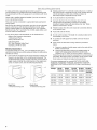
Electrical Connection
To properly install your oven, you must determine the type of
electrical connection you will be using and follow the instructions
provided for it here.
• Oven must be connected to the proper electrical voltage and
frequency as specified on the model/serial/rating plate. The
model/serial/rating plate is located under the control panel on
single ovens and under the control panel on the upper oven
cavity on double ovens. See the following illustrations.
Single Oven
A. Model/serial/rating plate
Double Oven
A. Model/serial/rating plate
Models rated from 7.3 to 9.6 kW at 240 volts (5.4 to 7.4 kW at
208 volts) require a separate 40-amp circuit. Models rated at
4.8 kW and below at 240 volts (3.6 kW and below at
208 volts) require aseparate 20-amp circuit.
A circuit breaker is recommended.
Connect directly to the circuit breaker box (or fused
disconnect) through flexible, armored or nonmetallic
sheathed, copper cable (with grounding wire). See "Make
Electrical Connection" section.
Flexible conduit from the oven should be connected directly
to the junction box.
Fuse both sides of the line.
Do not cut the conduit. The length of conduit provided is for
serviceability of the oven.
A UL listed or CSA approved conduit connector must be
provided.
If the house has aluminum wiring, follow the procedure
below:
1. Connect a section of solid copper wire to the ends of the
flexible conduit leads.
2. Connect the aluminum wiring to the added section of
copper wire using special connectors and/or tools
designed and UL listed for joining copper to aluminum.
Follow the electrical connector manufacturer's recommended
procedure. Aluminum/copper connection must conform with
local codes and industry accepted wiring practices.
For power requirements for models KOST107E, KOST100E,
KOSE507E, KOSE500E, KODE307E, KODE300E, KODE507E,
KODE500E, KODT100E and KODT107E, refer to the following
table.
Voltage Single Single Double Double Double
Thermal Convect Thermal Convect Convect/
Thermal
240 VAC 4100 W 4100 W 8300 W 8300 W 8300 W
208 VAC 3100 W 3100 W 6300 W 6300 W 6300 W
240 VAC 17.2 A 17.2 A 34.2 A 34.2 A 34.2 A
208 VAC 15.0 A 15.0 A 29.9 A 29.9 A 29.9 A
6

INSTALLATIONINSTRUCTIONS
, ,_ _H_,___:_
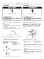
1. Decide on the final location for the oven. Avoid drilling or
cutting into house wiring during installation.
Excessive Weight Hazard
Use two or more people to move and install oven.
Failure to do so can result in back or other injury.
4=
Partially close the door to engage the door latch locks. The
door will stop at this point.
2. To avoid floor damage, set the oven onto cardboard prior to
installation. Do not use handle or any portion of the front
frame for lifting.
3. Remove the shipping materials and tape from the oven.
Remember to keep the corner posts and other materials that
may be needed for installation.
4. Remove the hardware package from inside the bag
containing literature.
5. Remove and set aside racks and other parts from inside the
oven.
6. Move oven and cardboard close to the oven's final location.
IMPORTANT: Use two hands to remove oven door. For double
ovens, repeat the process for each door.
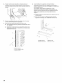
1. Prior to removing the oven door, prepare a surface where you
will place it. This surface should be flat and covered with a
soft blanket, or use the corner posts from your packaging
material.
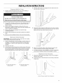
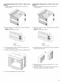
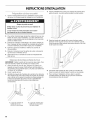
2. Open the oven door.
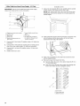
3. Locate the oven door hinge locks in both corners of the oven
door, and then rotate the hinge locks toward the oven door to
the unlocked position. If the door hinge lock is not rotated
fully (see illustration B), the door will not remove properly.
I A ..........................B
A. Oven door hinge lock in
locked position
B. Oven door hinge lock in
unlocked position
5. Using two hands, grasp the edges of the oven door. Lift and
pull the oven door toward you and remove. You may need to
gently shift door from side to side as you pull.
6. Set the oven door(s) aside on the prepared covered work
surface, with the oven door resting on its handle.
7. To continue with the oven installation, go to the "Positioning
Oven Feet for Multiple Cabinet Cutout Heights" section.
_,_ _ _a _ _ ,
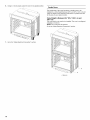
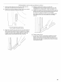
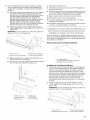
1. Using two hands, grasp side edges of door at the midpoint.
Face the oven cavity.
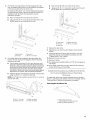
2. Locate the slots on each side of the oven cavity for the door
hinge locks.
L_ "A
A.Slot in the oven cavity for door hinge lock

3.
4.
5.
At a 45 ° angle, align door hinges with slots in the lower front
of the oven cavity. Slowly insert door, making sure you
maintain the 45° angle. You will know the door is engaged in
the slot when you feel a slight drop.
Lower the oven door to the fully open position. If the oven
door does not open to a full 90°, repeat steps 1 through 3.
Locate the oven door hinge locks in the corners of the oven
door, and rotate the hinge locks toward the oven cavity to the
locked position.
See Step 3 (illustration A) in the "Remove Oven Door(s)"
section for proper locked position.
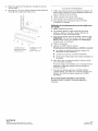
Single Ovens
The positioning of the oven feet allow asingle oven to be
installed in a cutout height between 261%d' and 297/16'' (68.4 cm
and 74.8 cm). Refer to the following instructions to position the
feet for the size of your cabinet cutout.
Cutout Height is Between 27%" and 28%" (70.2 cm and
72.7 cm)
The oven feet do not need to be changed. They are positioned
correctly as received.
Go to the "Make Electrical Connection" section.
6.
7.
Close the oven door.
When the hinges are properly installed and the door closed,
there should be an even gap between the door and the
control panel. If one side of the oven door is hanging lower
than the other, the hinge on that side is not properly installed.
8

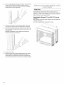
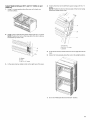
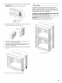
Cutout Height is Between 261%6'' and 2711A6"(68.4 cm and
70.3 cm)
1. Using 2 or more people, place the oven on its back on a
covered surface.
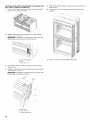
Cutout Height is Between 2811/16"and 29%6"(72.8 cm and
74.8 cm)
1. Using 2 or more people, place the oven on its back ona
covered surface.
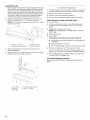
2. Remove the foot from the right front spacer by removing the
#8-18 x 3/8"screw.
NOTE: Do not remove the spacer.
2. Remove the foot from the right front spacer by removing the
#8-18 x 3/8"screw.
NOTE: Do not remove the spacer.
A
B
C
A. Spacer
B. Foot
C. #8-18 x _" screw
3. In the same manner, remove the feet on the right rear, left
front, and left rear of the oven.
4. Using 2 or more people, place the oven in its upright position.
3.
A
B
C
A. Spacer
B. Foot
C. #8-18 x _" screw
Rotate the foot 90 ° so the short side of the foot is positioned
toward the top of the oven.
4. Reinstall the foot to the spacer using the #8-18 x 3/8"screw
previously removed.
5. In the same manner, remove, rotate and reinstall the feet on
the right rear, left front, and left rear of the oven.
5. Go to the "Make Electrical Connection" section.

6=
Using 2 or more people, place the oven in its upright position.
Double Ovens
The positioning of the oven feet allow a double oven to be
installed in a cutout height between 487/8'' and 52¾e" (124.1 cm and
132.6 cm). Refer to the following instructions to position the feet
for the size of your cabinet cutout.
Cutout Height is Between 487/8'' 507/_6'' (124.1 cm and
128.1 cm)
The oven feet do not need to be installed. The oven is configured
correctly as received.
NOTE: Do not remove the spacers.
Go to the "Make Electrical Connection" section.
7. Go to the "Make Electrical Connection" section.
A
A. Spacers
10

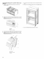
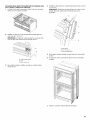
Cutout Height is Between 501/2'' and 511/8"(128.2 cm and
129.9 cm)
1. Using 2 or more people, place the oven on its back on a
covered surface.
2.
I
Install a foot on the left rear spacer using a #8-18 x 3/8"screw.
NOTE: Position the foot so the long side of the foot is facing
toward the top of the oven.
4=
Install a front foot on the left front spacer using a #8-18 x 3/8"
screw.
NOTE: Position the foot so the long side of the foot is facing
toward the inside of the oven.
B
A. Spacer
B. Foot
C. #8-18 x _" screw
3. In the same manner, install a foot on the right rear of the oven.
A. Front foot
B. #8-18 x _" screw
C. Spacer
5. In the same manner, install afront foot on the right front of the
oven.
6. Using 2 or more people, place the oven in its upright position.
7. Go to the "Make Electrical Connection" section.
11

Cutout Height is Between 513/16''and 523/_6'' (130.0 cm and
132.6 cm)
1. Using 2 or more people, place the oven on itsback on a
covered surface.
5. In the same manner, install a font foot on the right front of the
oven.
6. Using 2 or more people, place the oven in its upright position.
2,
Install a foot on the left rear spacer using a #8-18 x 3/8"screw.
NOTE: Position the foot so the short side of the foot is facing
toward the top of the oven.
3,
4.
A. Spacer
B. Foot
C. #8-18 x _" screw
In the same manner, install a foot on the right rear of the oven.
Install a front foot on the left front using a #8-18 x 3/8"screw.
NOTE: Position the foot so the long side of the foot is facing
toward the top of the oven.
7. Go to the "Make Electrical Connection" section.
B
A. Front foot
B. #8-18 x _" screw
C. Spacer
12

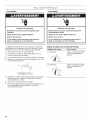
For Double Ovens
Electrical Shock Hazard
Disconnect power before servicing.
Use 8 gauge solid copper wire.
Electrically ground oven.
Failure to follow these instructions can result in death,
fire, or electrical shock.
For Single Ovens
Electrical Shock Hazard
Disconnect power before servicing.
Use 12 gauge solid copper wire.
Electrically ground oven.
Failure to follow these instructions can result in death,
fire, or electrical shock.
This oven is manufactured with a neutral (white) power supply
wire and a cabinet-connected green (or bare) ground wire twisted
together.
1. Disconnect power.
2. Feed the flexible conduit from the oven through the opening
in the cabinet.
3. Remove junction box cover, if it is present.
4. Install a UL listed or CSA approved conduit connector to the
junction box.
A. UL fisted or CSA approved conduit connector
5. Route the flexible conduit from the oven to the junction box
through a UL listed or CSA approved conduit connector.
6. Tighten screws on conduit connector.
7. See "Electrical Connection Options Chart" to complete
installation for your type of electrical connection.
Electrical Connection Options Chart
If your home has:
4-wire
Go to section:
4-Wire Cable from Home
Power Supply
3-wire
1/2"
3-Wire Cable from Home
Power Supply
4-Wire Cable from Home Power Supply
IMPORTANT: Use the 4-wire cable from home power supply in
the U.S. where local codes do not allow grounding through
neutral, New Branch circuit installations (1996 NEC), mobile
homes and recreational vehicles, new construction and in
Canada.
H
A. Cable from home power supply
B. Black wires
C. Red wires
D. 4-wire flexible conduit from
oven
E.Junction box
F. White wires
G. UL listed wire connectors
H. Green (or bare) ground wires
I. UL listed or CSA approved
conduit connector
1. Connect the 2 black wires (B) together using a UL listed wire
connector.
2. Connect the 2 red wires (C) together using a UL listed wire
connector.
3. Untwist white wire from green (or bare) ground wire coming
from the oven.
4. Connect the 2 white wires (F) together using a UL listed wire
connector.
5. Connect the green (or bare) ground wire (H) from the oven
cable to the green (or bare) ground wire (in the junction box)
using a UL listed wire connector.
6. Install junction box cover.
13

3-Wire Cable from Home Power Supply - U.S. Only
IMPORTANT: Use the 3-wire cable from home power supply
where local codes permit a 3-wire connection.
A
B
D
E
F
G
A. Cable from home power supply
B. Junction box
C. Black wires
D. White wires
E. Green (or bare) ground wire
(from oven)
F. 4-wire flexible conduit from
oven
G. Red wires
H. UL fisted wire connectors
I. UL listed or CSA approved
conduit connector
1. Connect the 2 black wires (C) together using a UL listed wire
connector.
2. Connect the 2 white wires (D) and the green (or bare) ground
wire (of the oven cable) using a UL listed wire connector.
3. Connect the 2 red wires (G) together using a UL listed wire
connector.
4.
Install junction box cover.
1=
Using 2 or more people, lift the oven partially into the cabinet
cutout. Use the oven opening as an area to grip.
NOTE: Push against seal area of the oven front frame when
pushing the oven into the cabinet. Do not push against the
outside edges.
\
/
2.
3.
4.
Push against the seal area of the front frame to push the oven
into the cabinet until the back surface of the front frame
touches the front wall of the cabinet.
Push oven completely into the cabinet and center the oven
into the cabinet cutout.
Remove the tape from black front trims.
• Securely fasten the oven to the cabinet using the #8-14 x
3_,,screws provided.
• Insert the screws through hole in black trim aligning with
hole in oven frame. Do not overtighten screws.
9
C ................................
A. Oven frame
B. Oven frame hole
C. Black trim piece
14

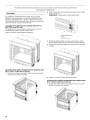
5=
The bottom vent and bottom vent trim (required when the
oven is installed with the feet in the tall position) are shipped
in the foam packing at the top of the oven.
To install only the bottom vent, see the following instructions.
To install both the bottom vent and the bottom vent trim for
installations with the feet in the tall position, see the
instructions in Step 6.
• Align vent tab (B) with oven frame (A) as shown.
• Using one #8-18 x 3/8"screw (D) on each side of the vent
tab (B), fasten the vent securely to the oven.
• Align vent tab (B) with oven frame (A) as shown.
• Using one #8-18 x 3/8"screw (E) on each side of the vent
tab (B), fasten the vent securely to the oven.
A
6.
B
C
A. Oven frame C. Oven vent
B. Vent tab D. #8-18x _" screws
On models with the feet installed in the tall position, the
bottom vent trim must also be installed. See the following
instructions to install.
Flex the upper vent piece (C) away from the lower vent
piece (D) to slide the bottom vent trim (B) between them.
Some force may be required to flex the upper vent trim (C)
away from the lower vent trim (D). Some force may also
be required to flex the bottom vent trim (B) and slide it
into position. Make sure screw holes are properly aligned
between the two pieces. See the following illustration.
• Install the bottom vent trim (B) to the lower vent piece (D)
using two #8-18 x 1A"screws on each side.
NOTE: On 27" (68.6 cm) models, only one #8-18 x W' screw is
used on each side.
B
D
A. Oven frame
B. Vent tab
C. Oven vent
D. Bottom vent trim
E. #8-18 x _" screw
7. Replace the oven racks.
8. Replace the oven door. See the "Replace Oven Door(s)"
section.
9. Check that the door is free to open and close. If it is not,
repeat the removal and installation procedures. See the
"Prepare Built-In Oven" section.
10. Repeat for lower oven door.
11. Reconnect power.
12. The display panel will light briefly, and "PF" should appear in
the display.
13. If the display panel does not light, reference the "Warranty"
section of the Use and Care Guide.
On single and double oven models installed above a warming
drawer, a warming drawer deflector kit must be installed. See the
"Tools and Parts" section for information on ordering.
Parts Supplied in Deflector Kit
A. #8-18x ¼" screw
B. Bottom vent trim
C. Upper vent piece
D. Lower vent piece
%¸¸¸¸g
A. Phillips head screws (4)
only 2screws for 27" (68.6 cm) size
B. Warming drawerdeflector (1)
15

Install Deflector Kit
1. Flex the upper vent piece (C) away from the lower vent piece
(D) to slide the warming drawer deflector (B) between them.
Some force may be required to flex the upper vent trim (C)
away from the lower vent trim (D). Some force may also be
required to flex the warming drawer deflector (B) and slide it
into position. Make sure screw holes are properly aligned
between the two pieces. See the following illustration.
2. Install the warming drawer deflector (B) to the lower vent
piece (D) using two #8-18 x 1A"screws on each side.
NOTE: On 27" (68.6 cm) models, only one #8-18 x 1¼.screw
is used on each side.
"D
A. #8-18 x ¼" screws
B. Warming drawer deflector
C. Upper vent piece
D. Lower vent piece
3. Align vent tab (B) with oven frame (A) as shown in the
following illustration.
4. Using one #8-18 x 3/8"screw (E)on each side of the vent tab
(B), fasten the vent securely to the oven.
1. Check that all parts are now installed. If there is an extra part,
go back through the steps to see which step was skipped.
2. Check that you have all of your tools.
3. Dispose of/recycle all packaging materials.
4. For oven use and cleaning, read the Use and Care Guide.
Check Operation of Single and Double Ovens
1. Turn on power.
2. At first use, set up the clock and any other preferences if
available. For more information, read the Use and Care
Guide.
3. Press BROIL on single oven models.
NOTE: Press UPPER BROIL or LOWER BROIL on double
oven models.
4. Set the temperature.
5. Press START.
If Oven(s) Does Not Operate, Check the Following:
• Household fuse is intact and tight; or circuit breaker has
not tripped.
• Electrical supply is connected.
• See "Troubleshooting" section in the Use and Care Guide.
6. When oven has been on for 5 minutes, feel for heat.
If you do not feel heat or if an error message appears in the
display, turn off the oven and contact a qualified technician.
7. Press UPPER CANCEL/LOWER CANCEL on double ovens,
or press CANCEL on single ovens.
If You Need Assistance or Service:
Please reference the "Warranty" section of the Use and Care
Guide.
B
E
A. Oven frame
B. Vent tab
C. Oven vent
C
D. Warming drawer deflector
E. #8-18x 3_,,screw
16

SECURITEDUFOURENCASTRE
Votre securite et celle des autres est tres importante.
Nous donnons de nombreux messages de securit_ importants dans ce manuel et sur votre appareil menager. Assurez-vous de
toujours lire tousles messages de securite et de vous y conformer.
Voici le symbole d'alerte de securit&
Ce symbole d'alerte de securite vous signale les dangers potentiels de decks et de blessures graves & vous
et & d'autres.
Tousles messages de securite suivront le symbole d'alerte de securite et le mot "DANGER" ou
"AVERTISSEMENT". Ces mots signifient •
Risque possible de d_cbs ou de blessure grave si vous ne
suivez pas imm_diatement les instructions.
Risque possible de d_cbs ou de blessure grave si vous
ne suivez pas les instructions.
Tous les messages de securite vous diront quel est le danger potentiel et vous disent comment reduire le risque de blessure et
ce qui peut se produire en cas de non-respect des instructions.
EXIGENCESD'INSTALLATION
Rassembler les outils et composants necessaires avant
d'entreprendre I'installation. Lire et observer les instructions
fournies avec chacun des outils de la liste ci-dessous.
Outils n_cessaires
• Tournevis Phillips
• Metre ruban
• Perceuse manuelle ou electrique (pour installation dans un
placard mural)
• Foret de 1" (2,5 cm) (pour installation dans un placard mural)
• Niveau
• Tournevis a lame plate
Pi_ces n_cessaires
• Connecteur de conduit (homologation UL ou CSA)
• Connecteurs de ills (homologation UL)
• Ensemble de deflecteur pour tiroir-rechaud (pour les fours
installes par-dessus un tiroir-rechaud)
Commander la )iece W10510613
27" (68,6 cm)
Commander la )iece W10531009
27" (68,6 cm)
Commander la )iece W10536338
inoxydable de 27" (68,6 cm)
Commander la )iece W10510614
30" (76,2 cm)
Commander la )iece W10531010
30" (76,2 cm)
Commander la )iece W10536339
inoxydable de 30" (76,2 cm)
Commander la )iece W10727416A pour I'ensemble en acier
inoxydable/noir de 30" (76,2 cm)
Pour commander, voir la section "Assistance ou service" du
Guide d'utilisation et d'entretien.
)our I'ensemble blanc de
)our I'ensemble noir de
)our I'ensemble en acier
)our I'ensemble blanc de
)our I'ensemble noir de
)our I'ensemble en acier
Ensemble d'installation en affleurement (pour four simple et
double installe en affleurement)
Commander la 3iece W10752684A
27" (68,6 cm)
Commander la 3iece W10752685A
27" (68,6 cm)
Commander la 3iece W10752686A
inoxydable de 27" (68,6 cm)
Commander la 3iece W10752680A
30" (76,2 cm)
Commander la 3iece W10752681A
30" (76,2 cm)
Commander la 3iece W10752683A
inoxydable de 30" (76,2 cm)
Commander la 3iece W10752682A
inoxydable/noir de 30" (76,2 cm)
Pour commander, voir la section "Assistance ou service" du
Guide d'utilisation et d'entretien.
3our I'ensemble blanc de
aour I'ensemble noir de
aour I'ensemble en acier
3our I'ensemble blanc de
aour I'ensemble noir de
aour I'ensemble en acier
aour I'ensemble en acier
Pi_ces fournies
• Vis n° 8-14 x 1" - Four simple (2), four double (4)
• Vis n° 8-18 x 3/8"- Event inferieur (2)
• Vis n° 8-18 x Y4"- Garniture de I'event inferieur (4)
• Vis n° 8-18 x 3/8"- Pieds du four double (4)
• Event inferieur
• Garniture de I'event
• Pieds arriere - four double (2)
• Pieds avant - four double (2)
• Bande de mousse - four simple*
Consulter les codes Iocaux. Verifier I'alimentation electrique
existante. Voir "Specifications electriques".
17

II est recommande de faire realiser tousles raccordements
electriques par un electricien qualifie agree.
*La bande de mousse n'est pas comprise avec les fours
doubles.
IMPORTANT • Observer les dispositions de tousles codes et
reglements en vigueur.
• Respecter les dimensions indiquees pour les ouvertures &
decouper dans les placards. Ces dimensions prennent en
compte les degagements de separation necessaires.
• L'espace d'installation doit permettre la formation d'une
enceinte complete autour de la partie encastree du four.
• Une source d'electricite avec liaison &la terre est necessaire.
Voir la section "Specifications electriques".
• Le boYtierde raccordement doit _tre situe & moins de 3"
(7,6 cm) au-dessous de la surface de support Iorsque le four
est installe dans un placard mural. Un trou de diametre 1"
(2,5 cm) ou plus doit avoir 6te perce dans I'angle arriere
gauche ou droit de la surface de support pour le passage du
c&ble d'alimentation de I'appareil jusqu'au boYtier de
connexion.
REMARQUE • Pour I'installation sous un plan de travail, on
recommande que le boYtier de connexion soit situ6 dans le
placard adjacent, & droite ou & gauche. Dans le cas de
I'installation du boYtier de connexion sur lemur arriere,
derriere le four, le boYtierde connexion doit _tre encastre et
place au centre de la partie superieure du placard.
La surface de support du four doit _tre robuste, horizontale et
en affleurement avec le bas de I'ouverture decoupee dans le
placard.
Le plancher doit pouvoir supporter le poids d'un four simple
de 129 Ib (59 kg) pour les modeles de 27" (68,6 cm) ou 154 Ib
(70 kg) pour les modeles de 30" (76,2 cm).
Le plancher doit pouvoir supporter le poids d'un four double
de 251 Ib (114 kg) pour les modeles de 27" (68,6 cm) ou
288 Ib (131 kg) pour les modeles de 30" (76,2 cm).
IMPORTANT •Afin d'eviter d'endommager les placards,
consulter le constructeur de la maison ou le fabricant des
placards pour determiner si les materiaux utilises peuvent
subir un changement de couleur, une destratification ou
d'autres dommages. Ce four a et6 con£;u conformement aux
exigences des normes UL et CSA International et respecte
les temperatures maximales permises de 194°F (90°C) pour
les placards en bois.
Installation sous un plan de travail (avec table de cuisson
install6e au-dessus) :
Les fours homologues pour ce type d'installation comportent une
etiquette d'homologation placee sur le dessus. Consulter "Four
installe sous la table de cuisson - Dimensions pour I'ouverture
decouper" (document distinct).
Dimensions du produit - Fours simples
B
D
Modeles de 27" (68,6 cm)
A.Hauteur hors-tout 283/4"
(72,8 cm) max.
B.Largeurd'encastrement 25 _"
(64,6 cm) max.
C.Hauteur d'encastrement 26 _"
(67,9 cm)
D.Profondeur d'encastrement
23 ¼"(59,1cm) max.
E.Largeurhors-tout 27" (68,6 cm)
F. 12" (30,5 cm) de I'arriere du
tableau de commandejusqu 'a
I'extr#mit# avant du serre-c#ble
G.48" (121,9cm)de Iongueur du
conduit flexible
Modeles de 30" (76,2 cm)
A. Hauteur hors-tout 283/4"
(72,8cm) max.
B.Largeurd'encastrement 28_"
(72,2cm) max.
C. Hauteurd'encastrement 26_"
(67,9cm)
D.Profondeur d'encastrement
23 ¼"(59,1 cm)
E.Largeur hors-tout 30"
(76,2cm)
F. 12" (30,5 cm) de I'arrieredu
tableau de commandejusqu 'a
I'extr#mit# avantdu serre-
c#ble
G.48" (121,9cm)de Iongueurdu
conduit flexible
18

Dimensions du placard - Fours simples
Four simple sous le plan de travail (sans table de cuisson au-
dessus)
_A_ B
E
_D_
Modeles de 27" (68,6 cm)
A. Largeur du placard 27"
(68,6 cm) min.
B. 1½" (3,8 cm) min. entre le
sommet de I'ouverture
d_coup_e et la face inf_rieure
du plan de travail
C. 5¼" (13,3 cm) entre le bas de
I'ouverture d_coup_e et le sol
D. Largeur de I'ouverture
d_coup_e 25 ½" (64,8 cm)
E. Hauteur de I'ouverture
d_coup_e 28" (71,2 cm) min.
Modeles de 30" (76,2 cm)
A. Largeur du placard 30"
(76,2 cm) min.
B. 1½" (3,8 cm) min. entre le
sommet de I'ouverture
d_coup_e et la face inf_rieure
du plan de travail
C. 5¼" (13,3 cm) entre le bas de
I'ouverture d_coup_e et le sol
D. Largeur de I'ouverture
d_coup_e 28½" (72,4 cm)
E. Hauteur de I'ouverture
d_coup_e 28" (71,2 cm) min.
Fours simples install_s dans un placard
F
B
E
Modeles de 27" (68,6 cm)
A. Largeur du placard 27"
(68,6 cm) min.
B. 1" (2,5 cm) entre le sommet de
I'ouverture d_coup_e et le bas
de la porte du placard
sup_rieur
C. 32" (81,3 cm) entre le bas de
I'ouverture d_coup_e et le sol
D. Largeur de I'ouverture
d_coup_e 25½" (64,8 cm)
E. 1½" (3,8 cm) min. entre le bas
de I'ouverture d_coup_e et le
sommet de la porte du placard
F. Hauteur de I'ouverture
d_coup_e recommand_e 28"
(71,2 cm)*
G. Profondeur de I'ouverture 24"
(60, 7 cm)
Modeles de 30" (76,2 cm)
A. Largeur du placard 30"
(76,2 cm) min.
B. 1" (2,5 cm) entre le sommet
de I'ouverture d_coup_e et le
bas de la porte du placard
sup_rieur
C. 32" (81,3 cm) entre le bas de
I'ouverture d_coup_e et le sol
D. Largeur de I'ouverture
d_coup_e 28 ½" (72,4 cm)
E. 1½" (3,8 cm) min. entre le bas
de I'ouverture d_coup_e et le
sommet de la porte du
placard
F. Hauteur de I'ouverture
d_coup_e recommand_e 28"
(71,2 cm)*
G. Profondeur de I'ouverture 24"
(60, 7 cm)
*REMARQUE : Pour les fours simples, la hauteur de I'ouverture
decoup6e peut _tre comprise entre 2615/le'' et 297/le'' (68,4 cm et
74,8 cm).
19

Dimensionsduproduit- Fours doubles
B
Dimensions du placard - Fours doubles
Fours doubles install_sdans un placard
A
F
B
E
Modeles de 27" (68,6 cm)
A. Hauteur hors-tout 51 _"
(130,0 cm) max.
B. Largeur d'encastrement 25 _"
(64,6 cm) max.
C. Hauteur d'encastrement
481_,, (124,0 cm)
D. Profondeur d'encastrement
23 ¼" (59,1 cm) max.
E.Largeur hors-tout 27" (68,6 cm)
F. 12" (30,5 cm) de I'arriere du
tableau de commande jusqu 'a
I'extr_mit_ avant du serre-
c&ble
G. 66" (167,6 cm) de Iongueur du
conduit flexible
Modeles de 30" (76,2 cm)
A. Hauteur hors-tout 51 _"
(130,0 cm) max.
B. Largeur d'encastrement 28 _"
(72,2 cm) max.
C. Hauteur d'encastrement 48 1_,,
(124,0 cm)
D. Profondeur d'encastrement
23 ¼" (59,1 cm) max.
E. Largeur hors-tout 30" (76,2 cm)
F. 12" (30,5 cm) de I'arriere du
tableau de commande jusqu'a
I'extr_mit_ avant du serre-c_ble
G. 66" (167,6 cm) de Iongueur du
conduit flexible
Modeles de 27" (68,6 cm)
A. Largeur du placard 27"
(68,6 cm) min.
B. 1" (2,5 cm) entre le sommet de
I'ouverture d_coup_e et la
porte du placard sup_rieur
C. 14_" (37,5 cm) entre le has de
I'ouverture d_coup_e et le sol
est la distance recommand_e.
4"-14_" (10,2-37,5 cm) entre
le bas de I'ouverture d_coup_e
et le sol est une distance
acceptable.
D. Largeur de I'ouverture
d_coup_e 25½" (64,8 cm)
E. 1½" (3,8 cm) min. entre le has
de I'ouverture d_coup_e et le
sommet de la porte du placard
F. Hauteur de I'ouverture
d_coup_e recommand_e
50¼" (127,6 cm) min.
G. Profondeur de I'ouverture 24"
(60,7 cm)
C
Modeles de 30" (76,2 cm)
A. Largeur du placard 30"
(76,2 cm) min.
B. 1" (2,5 cm) entre le sommet de
I'ouverture d_coup#e et la
porte du placard sup#rieur
C. 14 _" (37,5 cm) entre le bas de
I'ouverture d#coup#e et le sol
est la distance recommand#e.
4"-14_" (10,2-37,5 cm) entre
le bas de I'ouverture d#coup#e
et le sol est une distance
acceptable.
D. Largeur de I'ouverture
d#coup#e 28 ½" (72,4 cm)
E. 1½" (3,8 cm) min. entre le bas
de I'ouverture d#coup_e et le
sommet de la porte du placard
F. Hauteur de I'ouverture
d#coup_e recommand#e
50¼" (127,6 cm) min.
G. Profondeur de I'ouverture 24"
(60, 7 cm)
*REMARQUE : Pour les fours doubles, la hauteur de I'ouverture
decoup6e peut _tre comprise entre 487/8'' et 523/le'' (124,1 cm et
132,6 cm).
2O
La page est en cours de chargement...
La page est en cours de chargement...
La page est en cours de chargement...
La page est en cours de chargement...
La page est en cours de chargement...
La page est en cours de chargement...
La page est en cours de chargement...
La page est en cours de chargement...
La page est en cours de chargement...
La page est en cours de chargement...
La page est en cours de chargement...
La page est en cours de chargement...
-
 1
1
-
 2
2
-
 3
3
-
 4
4
-
 5
5
-
 6
6
-
 7
7
-
 8
8
-
 9
9
-
 10
10
-
 11
11
-
 12
12
-
 13
13
-
 14
14
-
 15
15
-
 16
16
-
 17
17
-
 18
18
-
 19
19
-
 20
20
-
 21
21
-
 22
22
-
 23
23
-
 24
24
-
 25
25
-
 26
26
-
 27
27
-
 28
28
-
 29
29
-
 30
30
-
 31
31
-
 32
32


KitchenAid KOSE500EBS04 Guide d'installation
- Taper
- Guide d'installation
dans d''autres langues
Documents connexes
Autres documents
-
Jenn-Air JJW2427DS Guide d'installation
-
Maytag MEW9630FZ Guide d'installation
-
Whirlpool WOD97ES0ES00 Guide d'installation
-
IKEA IBD550PWS00 Installation Instructions Manual
-
IKEA IBS650PXS00 Guide d'installation
-
Whirlpool GBS279PVS02 Guide d'installation
-
Maytag JJW8430DDS13 Guide d'installation
-
Jenn-Air JJW2830WS02 Guide d'installation