
Integrated Refrigeration Installation Guide

INTEGRATED REFRIGERATION
Contents
3 Integrated Refrigeration
4 Opening Dimensions
5 Electrical
5 Plumbing
6 Preparation
6 Anti-Tip Bracket
8 Placement
8 Alignment
9 Water Line
10 Custom Panels
12 Panel Installation
14 Completion
Features and specications are subject to change at any
time without notice. Visit subzero.com/specs for the most
up-to-date information.
Important Note
To ensure this product is installed and operated as safely
and efciently as possible, take note of the following types
of highlighted information throughout this guide:
IMPORTANT NOTE highlights information that is especially
important.
CAUTION indicates a situation where minor injury or product
damage may occur if instructions are not followed.
WARNING states a hazard that may cause serious injury or
death if precautions are not followed.
IMPORTANT NOTE: Throughout this guide, dimensions in
parentheses are millimeters unless otherwise specied.
IMPORTANT NOTE: Save these instructions for the local
electrical inspector.

subzero.com
|
3
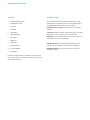
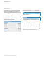
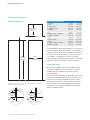
Product Information
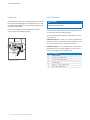
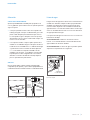
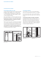
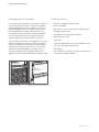
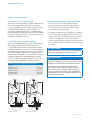
Important product information including the model and
serial number are listed on the product rating plate. For
column models, the rating plate is located inside the middle
drawer near the drawer guide opposite the hinge. For tall
and drawer models, the rating plate is located inside the
cabinet, to the left of the upper drawer. Refer to the illustra-
tions below.
If service is necessary, contact Sub-Zero factory certied
service with the model and serial number. For the name
of the nearest Sub-Zero factory certied service or for
questions regarding the installation, visit the contact & sup-
port section of our website, subzero.com or call Sub-Zero
customer care at 800-222-7820.
INTEGRATED REFRIGERATION
Tools and Materials
• Screwdrivers—standard, Phillips and Torx.
• Power drill.
• Drill bits (masonry bits required for concrete installation).
• Standard socket and wrench set.
• 2' and 4' levels.
• Tubing cutter.
• 3'
(.9 m) of
1
/4" OD copper, braided stainless steel or
PEX tubing.
• Saddle valve.
• Material to protect home, ooring and cabinetry during
installation.
Column models.
Tall and drawer models.
RATING
PLATE
RATING
PLATE

4
|
Sub-Zero Customer Care 800.222.7820
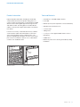
SITE PREPARATION
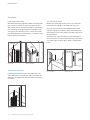
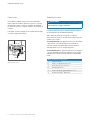
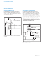
Opening Dimensions
INTEGRATED MODELS
25"
(635)
OPENING
DEPTH
W
OPENING WIDTH
H
OPENING
HEIGHT
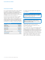
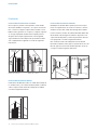
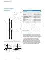
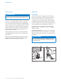
NOTE:
3
1
/2" (89) finished returns will be visible and should be finished to match cabinetry.
SIDE
VIEW
TOP VIEW
FRONT VIEW
3
1
/2" (89)
FINISHED
RETURN
FRAMELESS CABINETRY
3
/4"
(19)
TYPICAL
3
1
/2" (89)
FINISHED
RETURN
FILLER
FRAMED CABINETRY
W W
OPENING DIMENSIONS
COLUMN W H
IC-18FI 18" (457) 84" (2134)
IC-24R, IC-24FI 24" (610) 84" (2134)
IC-30R(ID), IC-30FI 30" (762) 84" (2134)
IC-36R(ID) 36" (914) 84" (2134)
TALL W H
IT-30R(ID), IT-30FI, IT-30CI(ID) 30" (762) 84" (2134)
IT-36R(ID), IT-36CI(ID) 36" (914) 84" (2134)
DRAWER W H
ID-24R, ID-24F(I) 24" (610) 34
1
/2" (876)
ID-27R 27" (686) 34
1
/2" (876)
ID-30R(P), ID-30F(I), ID-30C(I) 30" (762) 34
1
/2" (876)
ID-36R(P), ID-36C(I) 36" (914) 34
1
/2" (876)
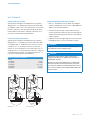
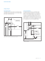
The depth of each integrated model is 24" (610). Allow for
panel thickness when planning the nished opening depth.
A minimum 3
1
/2" (89) nished return is required on all sides
of the opening. Framed cabinets will require additional
nished ller material behind the face frame for a proper
installation. Refer to the illustration.
DUAL INSTALLATION
When installing two units side by side in a dual installa-
tion, the opening width is the width of the two units added
together. A dual installation kit will be required for this instal-
lation. If a dual installation kit is not specied, a minimum
2"
(51) ller strip is required between units.
Dual installation kits are available through an authorized
Sub-Zero dealer. For local dealer information, visit the nd a
showroom section of our website, subzero.com. For ques-
tions regarding the installation, call Sub-Zero customer care
at 800-222-7820.

subzero.com
|
5
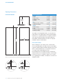
SITE PREPARATION
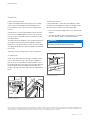
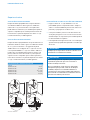
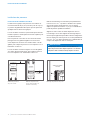
Electrical
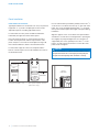
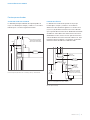
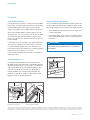
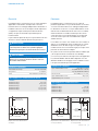
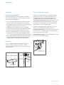
Installation must comply with all applicable electrical codes.
The electrical supply must be located within the shaded
area shown in the illustration and chart below. A separate
circuit, servicing only this appliance is required. A ground
fault circuit interrupter (GFCI) is not recommended and may
cause interruption of operation.
The electrical outlet must be positioned with the grounding
prong to the right of the thinner blades.
CAUTION
The outlet must be checked by a qualied electrician to
be sure that it is wired with the correct polarity. Verify
that the outlet is properly grounded.
WARNING
Do not use an extension cord, two-prong adapter or
remove the power cord ground prong.
ELECTRICAL REQUIREMENTS
Electrical Supply 115 VAC, 60 Hz
Service 15 amp
Receptacle 3-prong grounding-type
ELECTRICAL SUPPLY LOCATION
WIDTH A
18" Models 6" (152)
24" Models 9
1
/2" (241)
27" Models 11" (279)
30" Models 12
1
/2" (318)
36" Models 15
1
/2" (394)
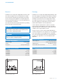
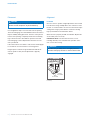
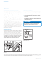
Plumbing
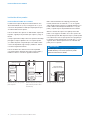
Installation must comply with all applicable plumbing codes.
The water supply line should be located within the shaded
area shown in the illustration below. The water supply line
should be connected to the house supply with an easily
accessible shut-off valve. Do not use self-piercing valves.
The water supply line must be ush to the oor and not
interfere with installation of the anti-tip bracket.
Column and tall models with an ice maker or water dis-
penser feature a water ltration system. An in-line lter is
required for drawer models with an ice maker when water
conditions have a high sediment content.
A reverse osmosis system can be used provided there is
constant water pressure of 35–120 psi
(2.4–8.3 bar) supplied
to the unit at all times. In this application, the water ltra-
tion system must be bypassed. Refer to water lter bypass
on page 15. A copper line is not recommended for this
application.
PLUMBING REQUIREMENTS
Water Supply Line
1
/4" OD copper, braided
stainless steel or PEX tubing
Water Pressure 35–120 psi
(2.4–8.3 bar)
Excess Water Line for Connection 36" (914)
WATER SUPPLY LOCATION
WIDTH A
18" Models 3" (76)
24" Models 5
1
/2" (140)
30" Models 6" (152)
36" Models 9" (229)
A
1
/4" (6)
1
/4" (6)
4
1
/4"
(108)
4
1
/2"
(114)
FLOOR
LEFT SIDE
OF OPENING
Electrical supply location.
3" (76)
6" (152)
RIGHT SIDE
OF OPENING
AREA EXTENDS
1
/2" (13)
FORWARD ON FLOOR
A
Water supply location.

6
|
Sub-Zero Customer Care 800.222.7820
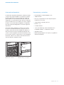
SITE PREPARATION
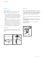
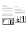
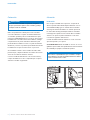
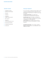
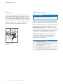
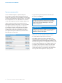
Preparation
Uncrate the unit and inspect for damage. Remove the wood
base and discard shipping bolts and brackets. Remove and
recycle packing materials. Do not discard the kickplate, anti-
tip bracket and hardware.
Remove the kickplate by extracting the two mounting
screws. Refer to the illustration below.
Anti-Tip Bracket
WARNING
To prevent the unit from tipping forward, the anti-tip
bracket must be installed.
The back of the anti-tip bracket must be installed 24" (610)
from the front of the unit (without panels).
Use all anti-tip bracket hardware as instructed for wood or
concrete oors.
IMPORTANT NOTE: For wood or concrete oor applications,
if the #12 screws do not hit a wall stud or wall plate, use the
#8 screws and #12 washers with the wall anchors.
IMPORTANT NOTE: In some installations the subooring or
nished oor may necessitate angling the screws used to
fasten the anti-tip bracket to the back wall.
ANTI-TIP HARDWARE
1 Anti-tip bracket
12 #12 x 2
1
/2" pan head screws
4
3
/8"–16 x 3
3
/4" wedge anchors
12 #12 at washers
4 #8–18 x 1
1
/4" truss head screws
4 Nylon Zip-it
®
wall anchors
SCREW
Kickplate removal.

subzero.com
|
7
SITE PREPARATION
CONCRETE WEDGE ANCHOR INSTALLATION:
1 Drill a
3
/8" (10) diameter hole any depth exceeding the
minimum embedment. Clean the hole or drill additional
depth to accommodate drill nes.
2 Assemble the washer and nut ush with the end of
anchor to protect threads. Drive the anchor through the
material to be fastened until the washer is ush with the
surface material.
3 Expand the anchor by tightening the nut 3–5 turns past
hand-tight position or to 25 foot-pounds of torque.
WARNING
Verify there are no electrical wires or plumbing in the
area which the screws could penetrate.
CAUTION
Always wear safety glasses and use other neces-
sary protective devices or apparel when installing or
working with anchors.
Anchors are not recommended for use in lightweight
masonry material such as block or brick, or for use in
new concrete which has not had sufcient time to cure.
The use of core drills is not recommended to drill holes
for the anchors.
Anti-Tip Bracket
WOOD FLOOR APPLICATION
After properly locating the anti-tip bracket in the opening,
drill pilot holes
3
/16" (5) diameter maximum in the wall studs
or wall plate. Use the #12 screws and washers to secure the
brackets. Verify the screws penetrate through the ooring
material and into wall studs or wall plate a minimum of
3
/4"
(19)
. Refer to the illustration and chart below.
CONCRETE FLOOR APPLICATION
After properly locating the anti-tip bracket in the opening,
drill pilot holes
3
/16" (5) diameter maximum in the wall studs
or wall plate. Drill
3
/8" (10) diameter holes into the concrete
a minimum of 1
1
/2" (38) deep. Use the #12 screws and
washers to secure the brackets to the wall, and use the
3
/8"
wedge anchors to secure the brackets to the oor. Verify the
screws penetrate wall studs or wall plate a minimum of
3
/4"
(19)
. Refer to the illustration and chart below.
ANTI-TIP BRACKET PLACEMENT
WIDTH A
18" Models 9" (229)
24" Models 12" (305)
27" Models 13
1
/2" (343)
30" Models 15" (381)
36" Models 18" (457)
A
A
SUBFLOORING
WOOD FLOOR
WALL PLATE
FINISHED
FLOORING
A
A
SUBFLOORING
CONCRETE
FLOOR
WALL PLATE
FINISHED
FLOORING
1
1
/2"(38)
min
Wood oor.
Concrete oor.

8
|
Sub-Zero Customer Care 800.222.7820
INSTALLATION
Placement
CAUTION
Before moving the unit into position, secure the door/
drawers closed and protect any nished ooring.
Use an appliance dolly to move the unit near the opening.
The front leveling legs are extended below the front rollers to
improve stability during placement. Once the unit is placed
in front of the opening, completely retract the front leveling
legs to allow the unit to be rolled into position. Front and
rear leveling legs can be adjusted from the front once the
unit is positioned.
If the unit has been on its back or side, it must stand upright
for a minimum of 24 hours before connecting power.
Plug the power cord into the grounded outlet and roll the
unit into position. Verify the anti-tip bracket is properly
engaged.
Alignment
LEVELING
Once the unit is in position, height adjustment can be made
from the front. Using a Phillips drive, turn clockwise to raise
the unit or counterclockwise to lower. Use the lowest torque
setting when using a power drill. Do not turn the leveling
legs by hand. Refer to the illustration below.
When the unit is properly leveled, door/drawer adjustments
are less likely to be necessary.
IMPORTANT NOTE: Level the unit to the oor, not sur-
rounding cabinetry. This could affect the operation of the
unit, such as door closing.
WARNING
To reduce the possibility of the unit tipping forward,
the front leveling legs must be in contact with the oor.
REAR
ADJUSTMENT
FRONT
ADJUSTMENT
Leveling.

subzero.com
|
9
INSTALLATION
Water Line
Purge the water line prior to nal connection to the unit. This
will remove any debris that may be present in the tubing
from installing the new water line. Connect the plastic tubing
from the unit to the house water supply line with the tting
connection kit provided. Check all water line ttings for
leaks.
Locate the water line in the notch as shown in the illustration
below.
IMPORTANT NOTE: If a reverse osmosis system used, it is
recommended that the water ltration system be bypassed
by removing the lter.
IMPORTANT NOTE: Water lines can not be exposed to
freezing temperatures.
WATER LINE
CONNECTION
NOTCH
Water line.
Alignment
DEPTH ADJUSTMENT
Adjust the depth of the unit to t ush with surrounding
cabinetry. Follow these steps for a precision t:
1 Place decorative panel on a protected work surface.
Place the panel thickness gauge next to the panel to
determine which notch corresponds with the panel thick-
ness. Refer to the illustration below. Once the proper
notch has been determined, mark that notch with a
marker.
2 With the door closed, position the top of the unit using
the panel thickness gauge. Refer to the illustration
below. Insert a #8 x
1
/2" stainless steel screw above the
hinge, then insert a #8 x
1
/2" pan head screw on the
handle side of the unit. For narrower units, the door may
need to be opened to access the handle side screw
location. Repeat the process to align the bottom.
ANCHORING
Once the top and bottom are aligned, verify doors and
drawers open properly, then install remaining screws in each
side trim.
PANEL THICKNESS
GAUGE
FRONT OF
UNIT
CABINETRY
FACE
FRAME
SCREW
SIDE TRIM
Panel thickness.
Unit depth.

10
|
Sub-Zero Customer Care 800.222.7820
Custom Panels
For integrated models, custom door panels and handle
hardware must be installed. Stainless steel panels are
available through an authorized Sub-Zero dealer. For local
dealer information, visit the nd a showroom section of our
website, subzero.com.
The thickness of the custom panel can vary. A minimum
5
/8" (16) thick panel is required, but the thickness can be
increased provided it does not exceed the maximum panel
weight indicated in the chart below. The depth of each
integrated model is 24"
(610). Allow for panel thickness when
planning the nished opening depth.
PANEL REQUIREMENTS
PANEL WEIGHT MAX
18" Column 45 lb (20 kg)
24" Column 60 lb (27 kg)
30" Column 75 lb (34 kg)
36" Column 75 lb (34 kg)
PANEL WEIGHT MAX
30" Tall (door) 50 lb (22 kg)
36" Tall (door) 60 lb (27 kg)
Drawer 15 lb (7 kg)
PANEL THICKNESS MIN
All Panels
5
/8" (16)
Reveals between panels can vary,
1
/8" (3) reveals are typical.
CAUTION
When installing a panel thicker than 1" (25), the 90° stop
may be required to prevent damage to the unit and
adjacent cabinetry.
CAUTION
As reveals between cabinetry and the unit decrease,
severe nger pinching can occur while door is closing.
Finish all sides of custom panels. They will be visible when
the door/drawer is open.
D-style handles are recommended. Door handles must be
located near the edge of the panel opposite the hinge and
should be centered top to bottom. Drawer handles must
be located near the top edge of each panel. Stainless steel
tubular and pro handles are avail able through an authorized
Sub-Zero dealer. For local dealer information, visit the nd a
showroom section of our website, subzero.com.
PANEL INSTALLATION

subzero.com
|
11
PANEL INSTALLATION
Custom Panels
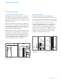
DOOR PANEL HEIGHT
The height of the custom door panel can extend beyond the
typical panel height, provided it does not exceed the weight
limit. Refer to the illustration below.
1
3
/
4
"
(45)
A DECORATIVE VALANCE
CANNOT EXTEND
BEYOND THIS PLANE
DOOR
PANEL
HINGE
24" (610)
TO BACK OF UNIT
84"
(2134)
1
/8" (3)
Upper valance (column and tall models)—side view.
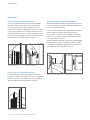
TOE KICK CLEARANCE
The height of the toe kick area can extend beyond the
typical toe kick height, provided it does not exceed the
dimensions in the illustration below. Toe kick heights from
2"
(51) to 3
7
/8" (98) require a reduced toe kick accessory
available through an authorized Sub-Zero dealer. For local
dealer information, visit the nd a showroom section of our
website, subzero.com. For questions regarding the installa-
tion, call Sub-Zero customer care at 800-222-7820.
24" (610)
TO BACK OF UNIT
VENTED
LOUVERS
HINGE
DOOR
PANEL
1
1
/8" (29)
MAX
TOE KICK
ADJUSTMENT
A DECORATIVE TOE KICK
CANNOT EXTEND
BEYOND THIS PLANE
2" (51)*
TO
6" (152)
FROM
FLOOR
*2" (51) to 3
7
/8" (98) requires sales accessory.
Toe kick—side view.

12
|
Sub-Zero Customer Care 800.222.7820
PANEL INSTALLATION
Panel Installation
DOOR PANEL INSTALLATION
Typical panel dimensions are based on an 84" (2134) nished
height with
1
/8" (3) reveals. Template placement must be
adjusted for panels exceeding typical dimensions.
For tall models, the door panel should be installed rst,
followed by the upper then lower drawer panel.
Place the panel face down on a protected work surface.
Position the template ush with the top and sides of the
panel. Verify the correct side of the template is being used,
then mark and drill holes. Refer to the illustration below.
For tall models, align the notch in the template with the
bottom of the door panel, then mark and drill holes. Refer to
the illustration below.
Use the T-20 torx drive provided to partially insert a #8 x
1
/2"
screw into the second hole from the top on each side of the
panel. The screws should be approximately
3
/16" (4) proud
of the panel and will support the weight of the panel during
installation.
Align the support screws on the back of the panel with the
slotted holes on both door mounting brackets. Opening the
door slightly may help with alignment. Once the panel is
supported by the screws, partially insert a #8 x
1
/2" screw
into the second hole from the bottom on each side of the
panel, but do not tighten.
CAUTION
As the reveal between cabinets and the unit decreases,
the potential exists for severe nger pinching if ngers
are placed in the opening when the door is closing.
BACK OF
DOOR PANEL
Door panel mounting.
BOTTOM OF
DOOR PANEL
EDGE OF DOOR PANEL
USE TABS FOR HINGE
SIDE PANEL EDGE ON
DUAL INSTALLATION
TOP OF
DOOR PANEL
84" APPLICATION
83 7/8" ACTUAL
EDGE OF DOOR PANEL
TOP OF DOOR PANEL
BOTTOM OF
DOOR PANEL
EDGE OF DOOR PANEL
USE TABS FOR HINGE
SIDE PANEL EDGE ON
DUAL INSTALLATION
TOP OF
DOOR PANEL
84" APPLICATION
83 7/8" ACTUAL
EDGE OF DOOR PANEL
BOTTOM OF
DOOR PANEL
Door panel template—top.
Door panel template—bottom
(tall models only).

subzero.com
|
13
PANEL INSTALLATION
PANEL ADJUSTMENT
Close the door and/or drawers, now adjustments can be
made to align panels and reveals.
For side-to-side adjustment, move panels side to side, then
install and tighten all mounting screws.
For up-and-down and in-and-out adjustments, slightly
loosen the bracket screws. Depending on the level of
adjustment required, it may be helpful to loosen all of the
bracket screws which will allow for maximum adjustment.
Once the bracket screws are loosened, rotate the cams
to make adjustments. After adjustments have been made,
tighten all bracket screws. Refer to the illustrations below.
BRACKET
SCREWS
IN-AND-OUT
CAM
BRACKET
SCREWS
UP-AND-DOWN
CAM
In-and-out adjustment.
Up-and-down adjustment.
Panel Installation
DRAWER PANEL INSTALLATION
Place the panel face down on a protected work surface.
Position the template ush with the top and sides of the
panel. Verify the correct side of the template is being used,
then mark and drill holes. Refer to the illustration below.
Use the T-20 torx drive provided, to partially insert a #8 x
1
/2"
screw into the second hole from the top on each side of the
panel. The screws should be approximately
3
/16" (4) proud
of the panel and will support the weight of the panel during
installation.
Align the support screws on the back of the panel with the
slotted holes on both drawer mounting brackets. Refer to
the illustration below. Opening the drawer slightly may help
with alignment. Once the panel is supported by the screws,
partially insert a #8 x
1
/2" screw into the second hole from
the bottom on each side of the panel, but do not tighten.
RIGHT EDGE OF DRA
WER PANEL
TOP HOLES
FOR UPPER
AND LOWER
DRAWERS
BOTTOM
HOLES FOR
LOWER
DRAWER
BOTTOM
HOLES FOR
UPPER
DRAWER
7021340
TOP OF
DRAWER PANEL
LEFT EDGE OF DRAWER PANEL
TOP OF DRAWER PANEL
BACK OF
DRAWER PANEL
Drawer panel template—top.
Drawer panel mounting.

14
|
Sub-Zero Customer Care 800.222.7820
INSTALLATION
Completion
DOOR TRIM INSTALLATION
After panels have been adjusted, install the decorative side
trim to the door/drawers. To install, start at the top and
align the trim with the front and rear anges on the bracket,
then snap into place by pushing the trim toward the back
of the panel. Once the top is secure, continue the installa-
tion downward until the remaining trim is completely secure.
Refer to the illustrations below.
TOP TRIM INSTALLATION
Identify the top trim strips by the notch on one end at the
bottom; this trim strip ts on the hinge side of the unit.
Insert the outer end of each trim strip behind the vertical
side trim. Engage the snap in the plastic side bracket and
slide the panel as far to the outside as possible. Refer to the
illustration below.
Rotate the inner end of each panel into the side ange of
the center shroud, next to the water lter access door. Press
on the trim strip to snap into place. Refer to the illustration
below.
Inner top trim.
Outer top trim.
DOOR TRIM
FRONT
FLANGE
REAR
FLANGE
Door trim.
Bracket anges.
SIDE TRIM INSTALLATION
Install the decorative trim strip to the handle side of tall
and column models. The side trim snaps over the bracket
attached to the handle side of the unit. Refer to the illustra-
tion below.
Side trim.

subzero.com
|
15
WATER FILTER BYPASS
If the water ltration system will not be utilized, it can be
placed in water lter bypass mode by removing the water
lter. Follow these steps to remove the water lter:
1 Pull out on the bottom edge of the access door and tilt
upward.
2 To remove the lter, rotate counterclockwise one-quarter
turn, then pull out. Refer to the illustration below.
WARNING
Follow all city and state laws when storing, recycling or
discarding unused refrigerators and freezers.
Completion
KICKPLATE INSTALLATION
Position the kickplate and install using the two mounting
screws. Refer to the illustration below. Kickplate must
be removable for service. The oor cannot interfere with
removal.
A maximum 6"
(152) decorative kickplate can be attached
to the factory-installed kickplate. The two rows of vented
louvers can be covered if door panel is a minimum 4"
(102)
from nished oor.
To install a decorative kickplate, remove paper backing from
the magnets and attach decorative kickplate to magnets.
Magnets may also be tacked into position to increase adhe-
sion. Magnets will allow decorative kickplate to be removed,
if necessary.
Turn power on by touching ‘power’ on the control panel.
90° DOOR STOP
A 105° door stop is built into the hinges of tall and column
units. To limit the door to 90°, open the door slightly less
than 90°, then use a standard screwdriver blade to remove
the existing clips from each hinge. Locate the 90° clips from
inside the plastic bag containing product literature, then
insert the 90° clips onto each hinge. Refer to the illustration
below.
INSTALLATION
SCREWMAGNET
CLIP
Kickplate installation.
90° door stop.
WATER FILTER
ACCESS DOOR
Water lter removal.
Sub-Zero, Sub-Zero & Design, Dual Refrigeration, The Living Kitchen, Great American Kitchens The Fine Art of Kitchen Design, and Ingredients are registered trademarks and service
marks of Sub-Zero, Inc. Wolf, Wolf & Design, Wolf Gourmet, W & Design and the color red as applied to knobs are registered trademarks and service marks of Wolf Appliance, Inc.
All other trademarks or registered trademarks are property of their respective owners in the United States and other countries.

2
|
Atención al cliente de Sub-Zero 800.222.7820
REFRIGERACIÓN INTEGRADA
Contenido
3 Refrigeración integrada
4 Dimensiones de abertura
5 Instalación eléctrica
5 Plomería
6 Preparación
6 Soporte antivuelco
8 Colocación
8 Alineación
9 Línea de agua
10 Paneles personalizados
12 Instalación de los paneles
14 Finalización
Aviso importante
Para garantizar que este producto sea instalado y operado
de la forma más segura y eciente posible, tome nota de los
siguientes tipos de información resaltada en esta guía:
AVISO IMPORTANTE resalta la información que es especial-
mente importante.
PRECAUCIÓN indica una situación en la que se pueden
sufrir heridas leves o provocar daños al producto si no se
siguen las instrucciones.
ADVERTENCIA indica peligro de que se produzcan heridas
graves o incluso la muerte si no se siguen las precauciones.
AVISO IMPORTANTE: En toda esta guía, las dimensiones
entre paréntesis son milímetros, a menos que se especique
lo contrario.

subzero.com
|
3
Información del producto
La información importante del producto, incluido el modelo
y número de serie de la unidad, se encuentran en la placa
de datos del producto. Para los modelos de columna, la
placa de datos se encuentra dentro del cajón medio del
refrigerador, cerca de la guía de cajón opuesta a la bisagra.
Para los modelos altos y los modelos con cajones, la placa
de datos se encuentra dentro del gabinete, a la izquierda
del cajón superior del refrigerador. Consulte las siguientes
ilustraciones.
Si necesita servicio, póngase en contacto con el centro
de servicio autorizado de Sub-Zero y tenga a la mano el
modelo y número de serie de la unidad. Para obtener los
datos del centro de servicio autorizado de Sub-Zero más
cercano o si tiene preguntas acerca de la instalación, visite
la sección de contacto y soporte técnico en nuestra página
de Internet, subzero.com o llame a la línea de atención al
cliente de Sub-Zero al 800-222-7820.
REFRIGERACIÓN INTEGRADA
Herramientas y materiales
• Destornilladores: estándar, Phillips y Torx.
• Taladro eléctrico.
• Brocas (se requieren brocas de mampostería para
instalación en concreto).
• Juego de llaves estándar y de vaso.
• Niveles 2' y 4'.
• Cortador de tubos.
• 3'
(0.9 m) de tubería de cobre, trenzada de acero
inoxidable o PEX de
1
/4" de diámetro exterior.
• Válvula de asiento.
• Material para proteger la casa, el piso y los gabinetes
durante la instalación.
Modelos de columna
Modelos alto y con cajones
PLACA DE
DATOS
PLACA DE
DATOS

4
|
Atención al cliente de Sub-Zero 800.222.7820
PREPARACIÓN DEL SITIO
Dimensiones de abertura
MODELOS INTEGRADOS
DIMENSIONES DE ABERTURA
COLUMNA ANCHO ALTURA
IC-18FI 18" (457) 84" (2134)
IC-24R, IC-24FI 24" (610) 84" (2134)
IC-30R(ID), IC-30FI 30" (762) 84" (2134)
IC-36R(ID) 36" (914) 84" (2134)
ALTO ANCHO ALTURA
IT-30R(ID), IT-30FI, IT-30CI(ID) 30" (762) 84" (2134)
IT-36R(ID), IT-36CI(ID) 36" (914) 84" (2134)
CAJÓN ANCHO ALTURA
ID-24R, ID-24F(I) 24" (610) 34
1
/2" (876)
ID-27R 27" (686) 34
1
/2" (876)
ID-30R(P), ID-30F(I), ID-30C(I) 30" (762) 34
1
/2" (876)
ID-36R(P), ID-36C(I) 36" (914) 34
1
/2" (876)
La profundidad de cada modelo integrado es 24" (610). Para
determinar la profundidad de la abertura ya con acabados,
considere el grosor del panel. En cada lado de la abertura,
se necesita un tubo de retorno de 3
1
/2" (89) como mínimo
con acabados. Los gabinetes con marco necesitarán
material de relleno de acabado detrás del marco frontal para
lograr una instalación adecuada. Consulte la ilustración.
INSTALACIÓN DOBLE
Al colocar dos unidades juntas en una instalación doble,
el ancho de la abertura es la suma del ancho de ambas
unidades. Para esta instalación se requiere un kit de
instalación doble.
Los kits de instalación doble están disponibles a través de
un distribuidor autorizado de Sub-Zero. Para obtener más
información acerca de los distribuidores locales, visite la
sección para encontrar una sala de exhibición de nuestro
sitio web, subzero.com. Si tiene preguntas con respecto
a la instalación, llame a la línea de atención al cliente de
Sub-Zero al 800-222-7820.
PROFUNDIDAD DE
LA ABERTURA DE
25"
(635)
Ancho
ANCHO DE
LA ABERTURA
Altura
ALTURA DE
LA ABERTURA
NOTA: Los tubos de retorno de
3
1
/2" (89) con acabados quedarán a la vista y deben
estar listos para ajustarse a los gabinetes.
VIST
A LATERAL
VISTA SUPERIOR
VISTA FRONTAL
TUBO DE
RETORNO DE
3
1
/
2
"
(89) CON
ACABADOS
GABINETE SIN MARCO
TÍPICO DE
3
/4"(19)
TUBO DE
RETORNO DE
3
1
/2" (89) CON
ACABADOS
RELLENO
GABINETE CON MARCO
Ancho Ancho

subzero.com
|
5
PREPARACIÓN DEL SITIO
Instalación eléctrica
La instalación debe cumplir con todos los códigos
eléctricos vigentes.
El suministro eléctrico debe colocarse
dentro del área sombreada que se muestra en la siguiente
ilustración. Es necesario un circuito independiente, que dé
servicio únicamente a este aparato. No es recomendable utilizar
un circuito de fallos de conexión a tierra (GFCI, por sus siglas en
inglés) ya que puede interrumpir el funcionamiento de la unidad.
El tomacorriente eléctrico debe colocarse de tal forma que
la clavija con conexión a tierra quede a la derecha de las
aspas más delgadas.
PRECAUCIÓN
Un electricista calicado debe revisar el tomacorriente
para asegurarse de que la conexión se haya
realizado con la polaridad correcta. Verique que el
tomacorriente esté debidamente conectado a tierra.
ADVERTENCIA
No utilice un cable de extensión, adaptador de dos
clavijas ni retire la clavija con conexión a tierra del
cable de alimentación.
REQUISITOS ELÉCTRICOS
Suministro eléctrico 115 V CA, 60 Hz
Interruptor de circuito 15 amperes
Receptáculo Conexión a tierra de 3 clavijas
UBICACIÓN DEL SUMINISTRO ELÉCTRICO
ANCHO A
Modelos de 18" 6" (152)
Modelos de 24" 9
1
/2" (241)
Modelos de 27" 11" (279)
Modelos de 30" 12
1
/2" (318)
Modelos de 36" 15
1
/2" (394)
A
1
/4" (6)
4
1
/4"
(108)
4
1
/2" (114)
VISTA FRONTAL
SUELO
LADO IZQUIERDO
DE LA ABERTURA
Ubicación del suministro
eléctrico.
Plomería
La instalación debe cumplir con todos los códigos de
plomería vigentes. La línea del suministro de agua debe
colocarse dentro del área sombreada que se muestra en
las siguientes ilustraciones. La línea del suministro de agua
debe conectarse al suministro doméstico con una válvula de
cierre de fácil acceso. Evite utilizar válvulas autoperforantes.
La línea de suministro de agua no debe sobresalir del nivel
de piso ni interferir en la instalación del soporte antivuelco.
Los modelos altos y de columna con fábrica de hielo o
dispensador de agua cuentan con un sistema de ltrado
de agua. Para los modelos de cajón con fábrica de hielo,
cuando el agua tiene un alto contenido de sedimentos,
es requisito instalar un ltro en la línea de agua.
Se puede utilizar un sistema de ósmosis inversa siempre y
cuando la presión del agua que llegue a la unidad se mantenga
de forma constante entre 35 y 120 psi
(de 2.4 a 8.3 bares) en
todo momento. En esta aplicación, se debe desviar el sistema
de ltrado de agua. Consulte la desviación del ltro de agua en
la página 15. No es recomendable utilizar una línea de cobre
para esta aplicación.
REQUISITOS DE PLOMERÍA
Línea de suministro de agua Tubería de cobre, trenzada de
acero inoxidable o PEX de
1
/4"
de diámetro exterior.
Presión del agua De 35 a 120 psi
(de 2.4 a 8.3 bares)
Línea de exceso de agua para
la conexión
36" (914)
UBICACIÓN DEL SUMINISTRO DE AGUA
ANCHO A
Modelos de 18" 3" (76)
Modelos de 24" 5
1
/2" (140)
Modelos de 30" 6" (152)
Modelos de 36" 9" (229)
3" (76)
VISTA FRONTAL
SUELO
VISTA SUPERIOR
PARED
POSTERIOR
1
/2"
(13)
6"
(152)
A
LÍNEA
DE AGUA
A
6"
(152)
LADO DERECHO
DE LA ABERTURA
LADO
DERECHO
DE LA
ABERTURA
3" (76)
VISTA FRONTAL
SUELO
VISTA SUPERIOR
PARED
POSTERIOR
1
/2"
(13)
6"
(152)
A
LÍNEA
DE AGUA
A
6"
(152)
LADO DERECHO
DE LA ABERTURA
LADO
DERECHO
DE LA
ABERTURA
Ubicación del suministro de
agua (parte posterior).
Ubicación del suministro de
agua (parte inferior).

6
|
Atención al cliente de Sub-Zero 800.222.7820
PREPARACIÓN DEL SITIO
Preparación
Desembale la unidad e inspeccione si tiene algún daño.
Retire la base de madera y deseche los pernos y soportes
de transporte. Retire y recicle los materiales de embalaje.
No deseche el zócalo, el soporte antivuelco ni las piezas de
montaje.
Para quitar el zócalo extraiga los dos tornillos para montaje.
Consulte la siguiente ilustración.
Soporte antivuelco
ADVERTENCIA
Para evitar que la unidad se vuelque hacia el frente,
debe instalarse el soporte antivuelco.
La parte posterior del soporte antivuelco debe instalarse a
24"
(610) del frente de la unidad (sin paneles).
Utilice todas las piezas de montaje de los soportes
antivuelco de acuerdo con las instrucciones para suelos de
madera o de concreto.
AVISO IMPORTANTE: Para aplicaciones en suelo de madera
o de concreto, si los tornillos del # 12 no alcanzan un
travesaño o la placa de pared, utilice tornillos del # 8 y
arandelas del # 12 con los anclajes de pared.
AVISO IMPORTANTE: En algunas instalaciones el contrapiso
o el suelo terminado pueden necesitar inclinar los tornillos
utilizados para sujetar el soporte antivuelco a la pared del
fondo.
PIEZAS DE MONTAJE ANTIVUELCO
1 Soporte antivuelco
12 Tornillos de cabeza plana #12 x 2
1
/2"
4 Anclas de cuña de
3
/8"–16 x 3
3
/4"
12 Arandelas planas #12
4 Tornillos de cabeza segmentada #8–18 x 1
1
/4"
4 Anclajes Nylon Zip-it
®
para pared
TORNILLO
Extracción del zócalo.
La page est en cours de chargement...
La page est en cours de chargement...
La page est en cours de chargement...
La page est en cours de chargement...
La page est en cours de chargement...
La page est en cours de chargement...
La page est en cours de chargement...
La page est en cours de chargement...
La page est en cours de chargement...
La page est en cours de chargement...
La page est en cours de chargement...
La page est en cours de chargement...
La page est en cours de chargement...
La page est en cours de chargement...
La page est en cours de chargement...
La page est en cours de chargement...
La page est en cours de chargement...
La page est en cours de chargement...
La page est en cours de chargement...
La page est en cours de chargement...
La page est en cours de chargement...
La page est en cours de chargement...
La page est en cours de chargement...
La page est en cours de chargement...
-
 1
1
-
 2
2
-
 3
3
-
 4
4
-
 5
5
-
 6
6
-
 7
7
-
 8
8
-
 9
9
-
 10
10
-
 11
11
-
 12
12
-
 13
13
-
 14
14
-
 15
15
-
 16
16
-
 17
17
-
 18
18
-
 19
19
-
 20
20
-
 21
21
-
 22
22
-
 23
23
-
 24
24
-
 25
25
-
 26
26
-
 27
27
-
 28
28
-
 29
29
-
 30
30
-
 31
31
-
 32
32
-
 33
33
-
 34
34
-
 35
35
-
 36
36
-
 37
37
-
 38
38
-
 39
39
-
 40
40
-
 41
41
-
 42
42
-
 43
43
-
 44
44


Sub-Zero ID27R Guide d'installation
- Taper
- Guide d'installation
- Ce manuel convient également à
dans d''autres langues
- English: Sub-Zero ID27R Installation guide
- español: Sub-Zero ID27R Guía de instalación
Documents connexes
-
Sub-Zero IC-27R Guide d'installation
-
Sub-Zero IW-18-LH Guide d'installation
-
-
-
Sub-Zero DEU2450RL Guide d'installation
-
Sub Zero IW-30A-RH Guide d'installation
-
-
Sub-Zero IW-24-RH Guide d'installation
-
-

