
1
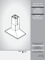
Use, Care, and
Installation Guide
Guide
d’utilisation,
d’entretien et
d’installation
Guía de
instalación, uso y
mantenimiento
READ AND SAVE THESE
INSTRUCTIONS
LISEZ CES
INSTRUCTIONS ET
CONSERVEZ-LES
LEA Y CONSERVE
ESTAS INSTRUCCIONES
LIB0138360A
Printed in Mexico
10/19
Models: ELI136S1
ELI142S1

2
ENGLISH
Contents
Important safety notice................................................................................................................................................................................................. 3
Electrical & installation requirements ................................................................................................................................................................ 4
Before installing the hood ...................................................................................................................................................................................... 4
Product dimensions ....................................................................................................................................................................................................... 4
List of materials................................................................................................................................................................................................................. 5
Parts supplied .............................................................................................................................................................................................................. 5
Parts not supplied ...................................................................................................................................................................................................... 5
Ducting options and examples.................................................................................................................................................................................. 6
Installation ......................................................................................................................................................................................................................... 7
Electrical connection................................................................................................................................................................................................ 10
Complete the installation........................................................................................................................................................................................ 10
Description of the hood................................................................................................................................................................................................. 11
Control.................................................................................................................................................................................................................................. 11
Maintenance ...................................................................................................................................................................................................................... 12
Warranty ........................................................................................................................................................................................................................... 13
APPROVED FOR RESIDENTIAL APPLIANCES
FOR RESIDENTIAL USE ONLY
READ AND SAVE THESE INSTRUCTIONS
PLEASE READ ENTIRE INSTRUCTIONS BEFORE PROCEEDING.
INSTALLATION MUST COMPLY WITH ALL LOCAL CODES.
IMPORTANT: Save these Instructions for the Local Electrical Inspector’s use.
INSTALLER: Please leave these Instructions with this unit for the owner.
OWNER: Please retain these instructions for future reference.
Safety Warning: Turn o power circuit at service panel and lock out panel, before wiring this appliance.
Requirement: 120 V AC, 60 Hz. 15 or 20 A Branch Circuit.

3
I
IMPORTANT SAFETY NOTICE
I CAUTION
FOR GENERAL VENTILATING USE ONLY. DO NOT USE TO
EXHAUST HAZARDOUS OR EXPLOSIVE MATERIALS OR
VAPOURS.
I WARNING
TO REDUCE THE RISK OF FIRE, ELECTRIC SHOCK, OR
INJURY TO PERSONS, OBSERVE THE FOLLOWING:
A. Use this unit only in the manner intended by the
manufacturer. If you have questions, contact the
manufacturer.
B. Before servicing or cleaning the unit, switch power o
at service panel and lock service panel disconnecting
means to prevent power from being switched on
accidentally.
When the service disconnecting means cannot be
locked, securely fasten a prominent warning device,
such as a tag, to the service panel.
C. Installation work and electrical wiring must be done by
qualified person(s) in accordance with all applicable
codes & standards, including fire-rated construction.
D. Sucient air is needed for proper combustion and
exhausting of gases through the flue (Chimney) of fuel
burning equipment to prevent back- drafting.
Follow the heating equipment manufacturers guideline
and safety standards such as those published by the
national fire protection association (NFPA), the american
society for heating, refrigeration and air conditioning
engineers (ASHRAE), and the local code authorities.
E. When cutting or drilling into wall or ceiling, do not
damage electrical wiring and other hidden utilities.
F. Ducted systems must always be vented to the outdoors.
I CAUTION
To reduce risk of fire and to properly exhaust air, be sure to
duct air outside - do not vent exhaust air into spaces within
walls, ceilings, attics, crawl spaces, or garages.
I WARNING
TO REDUCE THE RISK OF FIRE, USE ONLY METAL DUCT
WORK.
Install this hood in accordance with all requirements specified.
I WARNING
To reduce the risk of fire or electric shock, do not use this
hood with any external solid state speed control device.
I WARNING
TO REDUCE THE RISK OF A RANGE TOP GREASE FIRE.
a) Never leave surface units unattended at high settings.
Boilovers cause smoking and greasy spillovers that may
ignite. Heat oils slowly on low or medium settings.
b) Always turn hood ON when cooking at high heat or when
flambeing food (I.e. Crepes Suzette, Cherries Jubilee,
Peppercorn Beef Flambe’).
c) Clean ventilating fans frequently. Grease should not be
allowed to accumulate on fan or filter.
d) Use proper pan size. Always use cookware appropriate
for the size of the surface element.
I WARNING
TO REDUCE THE RISK OF INJURY TO PERSONS, IN THE
EVENT OF A RANGE TOP GREASE FIRE, OBSERVE THE
FOLLOWING:
a
a) SMOTHER FLAMES with a close-fitting lid, cookie sheet,
or other metal tray, then turn o the gas burner or the
electric element. BE CAREFUL TO PREVENT BURNS. If the
flames do not go out immediately, EVACUATE AND CALL
THE FIRE DEPARTMENT.
b) NEVER PICK UP A FLAMING PAN - you may be burned.
c) DO NOT USE WATER, including wet dishcloths or towels -
a violent steam explosion will result.
d) Use an extinguisher ONLY if:
1) You know you have a class ABC extinguisher, and
you already know how to operate it.
2) The fire is small and contained in the area where it
started.
3) The fire department is being called.
4) You can fight the fire with your back to an exit.
e) Ducted fans must always be vented to the outdoor.
a
Based on “Kitchen Fire Safety Tips” published by NFPA.
I CAUTION
Automatically Operated Device - To reduce the risk of
Injury disconnect from power supply before servicing.
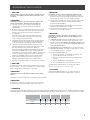
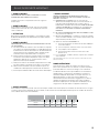
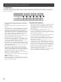
I WARNING
To Reduce The Risk Of Fire And Electric Shock, Install This Rangehood Only With Integral, In Line, and External Blower Models
Rated Maximum 7.7 A/ 926 W Or Integral Blowers Manufactured by Elica (for model references, see optional accessories table).
Integral Blower
(already included
with the hood)
In Line
Blower Kit 1200
KIT0154387
External
Blower Kit 1200
KIT0153054
HOOD MODEL A W A W A W
ELI136S1 7.7 926 7.7 926 7.5 897
ELI142S1 7.7 926 7.7 926 7.5 897

4
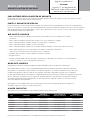
ELECTRICAL & INSTALLATION REQUIREMENTS
IMPORTANT
Observe all governing codes and ordinances.
It is the customer’s responsibility:
• To contact a qualified electrical installer.
• To assure that the electrical installation is adequate and in
conformance with National Electrical Code, ANSI/NFPA 70
— latest edition*, or CSA Standards C22.1-94, Canadian
Electrical Code, Part 1 and C22.2 No.0-M91-latest edition**
and all local codes and ordinances.
• If codes permit and a separate ground wire is used, it is
recommended that a qualified electrician determine that
the ground path is adequate.
• Do not ground to a gas pipe.
• Check with a qualified electrician if you are not sure range
hood is properly grounded.
• Do not have a fuse in the neutral or ground circuit.
IMPORTANT
• Save Installation Instructions for electrical inspector’s use.
• The range hood must be connected with copper wire only.
• The range hood should be connected directly to the fused
disconnect (Or circuit breaker) box through metal
electrical conduit.
• Wire sizes must conform to the requirements of the
National Electrical Code ANSI/NFPA 70 — latest edition*,
or CSA Standards C22.1-94, Canadian Electrical Code Part
1 and C22.2 No. 0-M91 - latest edition** and all local codes
and ordinances.
• A U.L.- or C.S.A.-listed conduit connector must be
provided at each end of the power supply conduit (at the
range hood and at the junction box).
Copies of the standards listed may be obtained from:
* National Fire Protection Association Batterymarch Park Quincy,
Massachusetts 02269
** CSA International 8501 East Pleasant Valley Road Cleveland,
Ohio 44131-5575
BEFORE INSTALLING THE HOOD
1 For the most ecient air flow exhaust, use a straight run
or as few elbows as possible.
CAUTION: Vent unit to outside of building, only.
2 At least two people are necessary for installation.
3 Fittings material is provided to secure the hood to most
types of walls/ceilings, consult a Qualified Installer,
check if they perfectly fit with your cabinet/wall.
4 Do not use flex ducting.
5 COLD WEATHER installations should have an additional
backdraft damper installed to minimize backward cold air
flow and a nonmetallic thermal break to minimize
conduction of outside temperatures as part of the
ductwork. The damper should be on the cold air side of
the thermal break.
The break should be as close as possible to where the
ducting enters the heated portion of the house.
6 Make up air: Local building codes may require the use of
Make-Up Air Systems when using Ducted Ventilation
Systems greater than specified CFM of air movement.
The specified CFM varies from locale to locale. Consult
your HVAC professional for specific requirements in your
area.
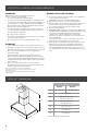
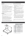
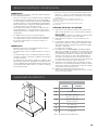
PRODUCT DIMENSIONS
A
B
C
E
F
G
D
Models
ELI136S1 ELI142S1
A 36” (91.4 cm) 42” (106.7 cm)
B 27” (68.6 cm)
C Max: 46
9
⁄16” (118.3 cm)
Min: 37
1
⁄2” (95.3 cm)
D* Max: 90” (229 cm)
Min: 60” (153 cm)
E 13
2
⁄16” (33.2 cm)
F 12” (30.5 cm)
G 8” (20.3 cm)
* with Long Chimney Extension Kit

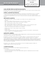
5
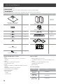
LIST OF MATERIALS
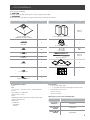
Removing the packaging.
I CAUTION
Remove carton carefully, Wear gloves to protect against sharp edges.
I WARNING
Remove the protective film covering the product before putting into operation.
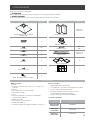
Supplied Part Pieces Supplied Part Pieces
Hood assembly and
LED lamps already installed
1
Lower and upper duct covers
Upper: 2
Lower: 2
5x45 mm
4
8” round air transition
1
4.2x8 mm
60
Torx adapter
#10: 1
#20: 1
3.5x9.5 mm
2
Vertical supports
Upper: 4
Lower: 4
3.5x6.5 mm
6
6x16 mm
4
Horizontal supports
3
Leveling screws
2
Mounting template
1
Duct cover brackets
4
Parts no supplied
Tools/Materials required
• Level
• Drill
• 1
1
⁄4” (3.2 cm),
1
⁄8” (3.2 mm), and
1
⁄16” (4.8 mm) drill bits
• Pencil
• Wire stripper or utility knife
• Tape measure or ruler
• Pliers
• Caulking gun and weatherproof caulking compound
• Jigsaw or keyhole saw
• Metal snips
• Screwdrivers:
- Flat-blade
- Phillips
Parts needed
• Home power supply cable
• 1 - ½” (12.7 mm) UL listed or CSA approved strain relief
• 3 UL listed wire connectors
• 1 wall or roof cap
• Metal vent system
Optional accessories and consumable parts
KIT # Part
Long Chimney
Extension
KIT0100317
in Line Blower
1200 Kit
KIT0154387
External Blower
1200 Kit
KIT0153054

6
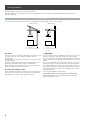
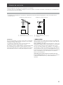
Ducting options
Closely follow the instructions set out in this manual.
All responsability, for any eventual inconveniences, damages or fires caused by not complying with the instructions in this
manual, is declined.
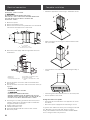
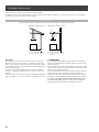
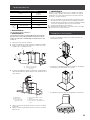
Ducting version
The hood is equipped with an 8” (20.3 cm) round transition for discharge of fumes to the outside.
Roof Venting Wall Venting
A
B
A
B
C
A. Roof cap
B. 8” (20.3 cm) round vent
A. Wall cap
B. 8” (20.3 cm) round vent
C. 90º elbow
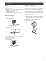
Preparation
Do not cut a joist or stud unless absolutely necessary. If a joist
or stud must be cut, then a supporting frame must be
constructed.
Fittings material is provided to secure the hood to most types
of walls/ceilings.
However, a qualified technician must verify suitability of the
materials in accordance with the type of wall/ceiling.
Before making cutouts, make sure there is proper clearance
within the ceiling or wall for exhaust vent.
Recommended installation height:
Hood installation height above cooktop is the users preference.
The lower the hood is above the cooktop, the more efficient
the capturing of cooking odors, grease and smoke.
I CAUTION
For gas cooktop & range installations: Mount the hood so the
bottom is at least 36” (91.4 cm) above the cooking surface.
For electric/induction cooktop & range installations: Mount the
hood so the bottom is at least 30” (76.2 cm) above the cooking
surface.
There is no maximum mounting height, however, we recom-
mend mounting the hood no greater than 36” (91.4 cm) above
the cooking surface. For every inch (2.54 cm) above 36” (91.4
cm), fume and moisture capture eciency diminishes at an in-
creasing rate and may not deliver an acceptable level of venti-
lating performance.
This hood is intended for household use.
PLEASE READ THE INSTALLATION MANUAL FOR SPECIFIC
APPLICATION. Check your ceiling height and hood height
before selecting your hood.

7
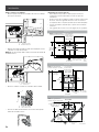
Installation
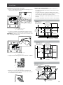
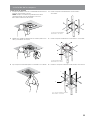
Mounting the range hood blower
• Slide the rear mounting plate flange under the bracket.
A
B
A. Bracket
B. Blower mounting plate
• Push the front end of the mounting plate up and snap into
spring tab.
NOTE: The spring tab should be outside of the slot in the
mounting plate.
A
B
A. Blower mounting plate
B. Spring tab
• Align mounting holes and install 4 - 6 x 16 mm screws.
B
A
A. Screw with lock washer
B. Mounting hole
• Attach power cord connector to connector on wire box on
blower motor mounting plate.
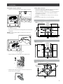
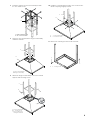
Ceiling support structures
• This vent hood is heavy. Adequate structure and support
must be provided in all types of installations.
• At the hood location, install 2”x 4” cross framing between
ceiling joists as shown (2”x 4” are required to support
the weight of the hood).
• Arrange cross framing in the ceiling to suit the existing
structure.
Your ceiling joists will be like one of the following:
Example A
NOTE: Top view ceiling joists
parallel to front of hood
10
1
⁄16” (25.5 cm)
install cross-
framing
symmetrically
over duct/cooktop
Centerline
16”
(40.6 cm)
joist spacing
7
1
⁄16”
(17.9cm)
Ø 8
1
⁄4” (21
cm) duct
2 x 4 cross
framing
Align duct to
center of cooktop
Hood front
Cooktop
outline
Example B
2 x 4 cross
framing
Align duct to
center of cooktop
Hood front
Cooktop
outline
NOTE: Top view ceiling joists
parallel to front of hood
10
1
⁄16” (25.5 cm)
install cross-
framing zz
symmetrically
over duct/cooktop
Centerline
Ø 8
1
⁄4” (21
cm) duct
7
1
⁄16”
(17.9cm)
16”
(40.6 cm)
joist spacing
Example C
NOTE: Top view ceiling joists
parallel to front of hood
Align duct to
center of cooktop
Hood front
Cooktop
outline
2 x 4 cross
framing
Ø 8
1
⁄4” (21
cm) duct
7
1
⁄16”
(17.9cm)
16”
(40.6 cm)
joist spacing
10
1
⁄16” (25.5 cm)
install cross-framing
symmetrically over
duct/cooktop
Centerline

8
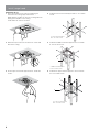
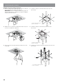
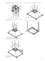
Install range hood
Install Range Hood
1 Place the template in the ceiling considering the
instructions for ceiling support structures.
NOTE: Always consider the front of hood legend when
playing the template on the ceiling.
It will define the control’s location.
2 Mark with a pencil the hole locations for screws and
duct in the ceiling.
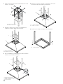
3 Fix the upper horizontal support with 4 - 5x45 mm
screws.
4 Install the lower horizontal support with 8 - 4.2 x 8 mm
screws.
A. Lower horizontal support
B. 8 - 4.2 x 8 mm screws
A
B
5 Install the middle horizontal support to the hood with
8 - 4.2 x 8 mm screws.
A. Middle horizontal support
B. 8 - 4.2 x 8 mm screws
A
B
6 Install the 4 upper vertical supports to the hood with
16 - 4.2 x 8 mm screws.
A. 4 - Upper vertical supports
B. 16 - 4.2 x 8 mm screws
B
A

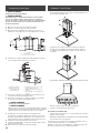
9
7 Install the structure to the horizontal support with
16 - 4.2 x 8 mm screws.
A. Upper horizontal support
B. 16 - 4.2 x 8 mm screws
B
A
8 Using 2 or more people, lift the range hood assembly
under the structure.
A. Lower vertical supports
B. Range hood assembly
A
B
9 Attach the range hood assembly to the lower vertical
supports with 2 leveling screws.
B
A
C
B
A. Lower vertical support
B. 2 - Leveling screws
C. Place leveling screws
through the structure
10 Install the 4 vertical supports with 8 - 4.2 x 8 mm screws.
Check everything is tightly screwed.
A
B
A. 4 - Lower vertical supports
B. 8 - 4.2 x 8 mm screws
11 Remove the 2 leveling screws from the structure.
A. 2 - Leveling screws
A
A

10
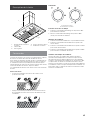
Complete installation
• Attach the upper duct covers using 6 - 3.5x6.5 mm screws.
• Place lower duct covers using one plastic bracket at each
side (4 needed).
• The lower duct cover shall be secured to rangehood by 4
screws.
• Install the grease filter and turn power on at service panel.
• Check operation of the hood.
If range hood does not operate:
• Check that the circuit breaker is not tripped or the house
fuse blown.
• Disconnect power supply. Check that wiring is correct.
To get the most ecient use from your new range hood, read
the “Description of the Hood” and “Control” sections.
Keep your Installation Instructions and Use and Care Guide
close to range hood for easy reference.
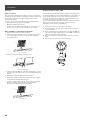
Electrical connection
I WARNING
ELECTRICAL SHOCK HAZARD.
I WARNING
DISCONNECT POWER BEFORE SERVICING.
REPLACE ALL PARTS AND PANELS BEFORE OPERATING.
FAILURE TO DO SO CAN RESULT IN DEATH OR
ELECTRICAL SHOCK.
1 Disconnect power.
2 Remove terminal box cover.
3 Remove the knockout in the terminal box cover and install
a UL listed or CSA approved
1
⁄2” strain relief.
C
B
A
A. Knockout
B. Junction box cover
C. Junction box cover screws
4 Run home power supply cable through strain relief, into
terminal box.
A
B
C
D
E
F
A.White wires
B. Black wires
C. UL listed wire connectors
D. Green, Bare or Yellow/Green wires
E. Home power supply
F. UL listed or CSA approved ½” strain
relief
5 Use UL listed wire connectors and connect black wires
(B) together.
6 Use UL listed wire connectors and connect white wires (A)
together.
I WARNING
ELECTRICAL SHOCK HAZARD.
I WARNING
ELECTRICALLY GROUND BLOWER.
CONNECT GROUND WIRE TO GREEN AND YELLOW
GROUND WIRE IN TERMINAL BOX. FAILURE TO DO SO
CAN RESULT IN DEATH OR ELECTRICAL SHOCK.
7 Connect green (or bare) ground wire from home power
supply to yellow-green ground wire (D) in terminal box
using UL listed wire connectors.
8 Tighten strain relief screw.
9 Install terminal box cover.
10 Check that all light bulbs are secure in their sockets.
11 Reconnect power.

11
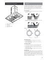
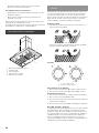
Description of the hood
5
1
4
3
2
1. Blower and light controls
2. LED lamps
3. Grease filter
4. Grease filter handle
5. Duct covers
Control
The range hood is designed to remove smoke, cooking vapors
and odors from the cooktop area. For best results, start the
hood before cooking and allow it to operate several minutes
after the cooking is complete to clear all smoke and odors
from the kitchen. The hood controls are located on the center
side of the range hood.
Recessing Knobs
• You can hide control knobs by depressing them until flush
with the hood body.
• Pressing the knobs again will lower the knobs, and enable
the user to operate the lights and blower.
Controls
A
B
A. Lamps knob B. Blower knob
Operating the lamps
1. Turn the light switch to the “ON” position to turn the
range hood lights On.
2. Turn the light switch to the “OFF” position to turn the
range hood lights O.
Operating the blower
1. Turn the blower switch at “1” to turn the range hood on.
2. Turn the blower switch to the desired speed position.
3. Turn the blower switch to the “MAX” position to turn the
range hood on High.
4. Turn the blower switch to the “OFF” position to turn the
range hood blower O.
Auto On blower
The range hood is equipped with a sensor to automatically turn
on the blower when excessive heat is detected in the control
area. When the blower switch is in the “Off” position, this sensor
will turn the blower to high speed when necessary. When the
heat decreases, the blower will turn off. When the blower
switch is in the On position, the heat sensor is not active and
the range hood functions normally.

12
Maintenance
Cleaning
Exterior surfaces:
To avoid damage to the exterior surface, do not use steel wool
or soap-filled scouring pads. Rub in direction of the grain line
to avoid scratching the surface.
Always wipe dry to avoid water marks.
• Stainless Steel Cleaner and Polish.
• Mild liquid detergent and water.
• Wipe with damp soft cloth or nonabrasive sponge, then
rinse with clean water and wipe dry.
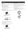
Metal filters and drip trays:
1. Use 2 hands to remove filters.
2. Grasp filter handles, pull toward the front of range hood
and pull down on the rear handle to remove. Repeat for
each filter.
A
A. Grease filter
3. Remove grease drip tray.
A
A. Drip tray
4. Wash metal filters and grease trays as needed in
dishwasher or hot detergent solution to clean.
5. Replace grease drip tray.
6. Reinstall filters, grasp filter handles and place front edge
of filter into the hood.
7. Push up on the back handle and set rear of filter into the
drip tray to secure. Repeat for each filter.
A
A. Grease filter
Replacing a LED Lamp
Turn off the range hood and allow the LED lamp to cool.
To avoid damage or decreasing the life of the new lamp, do
not touch lamp with bare fingers. Replace lamp, using tissue
or wearing cotton gloves to handle lamp.
If new lamps do not operate, make sure the lamps are inserted
correctly before calling service.
1 Disconnect power.
2 Push up on the lens and turn it counterclockwise.
3 Remove the lamp and replace it with a 120-volt, 7.5 W watt
maximum LED lamp with a GU10 base. Turn it clockwise to
lock it into place.
4 Repeat steps 2-3 for the other lamps if needed.
5 Reconnect power.

13
ELICA North America
TWO-YEAR LIMITED WARRANTY
TO OBTAIN SERVICE UNDER WARRANTY
Owner must present proof of original purchase date. Please keep a copy of your dated proof of purchase (sales slip) in
order to obtain service under warranty.
PARTS AND SERVICE WARRANTY
For the period of two (2) years from the date of the original purchase, Elica will provide free of charge, non consumable
parts or components that failed due to manufacturing defects. During these two (2) years limited warranty, Elica will also
provide free of charge, all labor and in-home service to replace any defective parts.
WHAT IS NOT COVERED
• Damage or failure to the product caused by accident or act of God, such as, flood, fire or earthquake.
• Damage or failure caused by modification of the product or use of non-genuine parts.
• Damage or failure to the product caused during delivery, handling or installation.
• Damage or failure to the product caused by operator abuse.
• Damage or failure to the product caused by dwelling fuse replacement or resetting of circuit breakers.
• Damage or failure caused by use of product in a commercial application.
• Service trips to dwelling to provide use or installation guidance.
• Light bulbs, metal or carbon filters and any other consumable part.
• Normal wear of finish.
• Wear to finish due to operator abuse, improper maintenance, use of corrosive or abrasive cleaning products/pads and
oven cleaner products.
WHO IS COVERED
This warranty is extended to the original purchaser for products purchased for ordinary residential use in North America
(Including the United States, Guam, Puerto Rico, US Virgin Islands & Canada).
This warranty is non-transferable and applies only to the original purchaser and does not extend to subsequent owners of
the product. This warranty is made expressly in lieu of all other warranties, expressed or implied, including, but not limited
to any implied warranty of merchantability or fitness for a particular purpose and all other obligations on the part of Elica
North America, provided, however, that if the disclaimer of implied warranties is ineective under applicable law, the dura
-
tion of any implied warranty arising by operation of law shall be limited to two (2) years from the date of original purchase
at retail or such longer period as may be required by applicable law.
Th
is warranty does not cover any special, incidental and/or consequential damages, nor loss of profits, suered by the
original purchaser, its customers and/or the users of the Products.
WHO TO CONTACT
To obtain service under warranty or for any service related question:
• Elica North America Service, call at 1 888 732 8018
• For Eastern Canada, call AGI Services at 1 888 651 2534 Ask for the service department
• elica@servicepower.com
Register your product in
elica.com
and earn a 3
rd
year of factory
warranty, covering all parts
plus in-home labor.

14
FRANÇAIS
Table des matières
Avis de sécurité important ......................................................................................................................................................................................... 15
Exigences électriques et d’installation ............................................................................................................................................................. 16
Avant d’installer la hotte ........................................................................................................................................................................................ 16
Dimensions du produit ................................................................................................................................................................................................. 16
Liste des pièces ............................................................................................................................................................................................................... 17
Pièces fournies ........................................................................................................................................................................................................... 17
Pièces non fournies .................................................................................................................................................................................................. 17
Méthodes d’evacuation ................................................................................................................................................................................................. 18
Installation ......................................................................................................................................................................................................................... 19
Connexion électrique................................................................................................................................................................................................ 22
Achever l’installation ................................................................................................................................................................................................ 22
Description de la hotte ................................................................................................................................................................................................ 23
Commandes ..................................................................................................................................................................................................................... 23
Entretien ............................................................................................................................................................................................................................ 24
Garantie .............................................................................................................................................................................................................................. 25
APPROUVÉ POUR LES APPAREILS DE TYPE RÉSIDENTIEL
POUR UNE UTILISATION RÉSIDENTIELLE SEULEMENT
LISEZ CES INSTRUCTIONS ET CONSERVEZ-LES
VEUILLEZ LIRE CES INSTRUCTIONS AU COMPLET AVANT DE COMMENCER.
L’INSTALLATION DE L’APPAREIL DOIT RESPECTER TOUS LES CODES EN VIGUEUR.
IMPORTANT : Conservez ces instructions afin de pouvoir les remettre à l’inspecteur-électricien de votre région.
INSTALLATEUR : Veuillez laisser ces instructions avec l’appareil pour le propriétaire.
PROPRIÉTAIRE : Veuillez conserver ces instructions pour pouvoir vous y référer plus tard.
Avertissement de sécurité : Coupez l’alimentation du circuit dans le panneau électrique et verrouillez le
panneau avant de raccorder les fils de cet appareil.
Exigence : 120 V c.a., 60 Hz circuit de dérivation de 15 V c.a., 20 Hz, de 15 ou 20 A.
I
AVIS DE SÉCURITÉ IMPORTANT
I ATTENTION
UTILISER CET APPAREIL À DES FINS DE VENTILATION
GÉNÉRALE SEULEMENT. NE PAS UTILISER CET APPAREIL
POUR ÉVACUER DES MATÉRIAUX OU DES VAPEURS
DANGEREUX OU EXPLOSIFS.
I AVERTISSEMENT
POUR RÉDUIRE LES RISQUES D’INCENDIE, DE CHOC
ÉLECTRIQUE ET DE BLESSURE, RESPECTER LES DIRECTIVES
SUIVANTES:
A. Utiliser cet appareil uniquement aux fins prévues par le
fabricant. Si vous avez des questions à propos de l’appareil,
communiquez avec le fabricant.
B. Avant de faire l’entretien de l’appareil ou de le nettoyer,
coupez l’alimentation dans le panneau électrique et
verrouillez le panneau en bloquant le dispositif permettant
d’empêcher d’activer l’alimentation accidentellement. S’il
n’est pas possible de verrouiller l’accès au panneau, fixez
une étiquette très voyante au panneau électrique.
C. Une personne qualifiée doit eectuer l’installation et le
câblage des fils électriques en conformité avec tous les
codes et toutes les normes, y compris la cote de résistance
au feu.
D. Il est important de prévoir susamment d’air pour assurer
une bonne combustion de l’équipement de chaue et l’éva-
cuation adéquates des gaz par le conduit de cheminé afin
de prévenir les refoulements d’air. Respectez les directives
et les normes de sécurité des fabricants de l’équipement
de chauage, comme celles publiées par la National Fire
Protection Association (NFPA), la American Society for
Heating, Refrigeration and Air Conditioning Engineers
(ASHRAE) et le code des autorités de votre région.
E. Au moment de couper ou de percer un mur ou un plafond,
assurez-vous de ne pas endommager la filerie électrique
ou tout autre accès à un service publique.
F. Il faut toujours évacuer à l’extérieur les systèmes conduit.
I ATTENTION
Pour réduire les risques d’incendie et évacuer l’air correctement,
assurez-vous que le conduit mène à l’extérieur; il ne faut pas
évacuer l’air dans l’espace entre les murs, dans les plafonds, dans
les greniers, les vides sanitaires ou les garages.

15
I
AVIS DE SÉCURITÉ IMPORTANT
I AVERTISSEMENT
POUR RÉDUIRE DES RISQUES D’INCENDIE, UTILISEZ
UNIQUEMENT DES CONDUITS EN MÉTAL.
Installez cette hotte en respectant toutes les exigences
mentionnées.
I AVERTISSEMENT
Pour réduire les risques d’incendie et de choc électrique,
n’utilisez pas cette hotte avec un contrôleur de vitesse à
semi-conducteurs.
I ATTENTION
Dispositif à commande automatique - pour réduire le risque
de Blessure Débrancher de l’alimentation électrique avant la
maintenance.
I AVERTISSEMENT
POUR RÉDUIRE LES RISQUES D’INCENDIE DE GRAISSE SUR
LES CUISINIÈRES.
a) Ne laissez jamais la cuisinière sans surveillance lorsqu’elle
est réglée à une haute température. Les débordements par
bouillonnement causent de la fumée et des débordements
de gras qui peuvent s’enflammer. Faites chauer l’huile
lentement, à une température basse ou moyenne.
b) Faites toujours fonctionner la hotte lorsque vous utilisez
la cuisinière à une haute température ou que vous faites
flamber des aliments (P. ex.: crêpes Suzette, cerises
jubilées, boeuf au poivre flambé).
c) Nettoyez les hélices de ventilation fréquemment. Il ne faut
pas que la graisse s’accumule sur les filres ou les hélices.
d) Utilisez le bon format de casserole. Utilisez toujours un
chaudron de taille approprié à l’élément de la cuisinière.
e) Convient pour utilisation dans la zone de cuisson domestique.
I AVERTISSEMENT
POUR ÉVITER DE BLESSER QUELQU’UN LORS D’UN
INCENDIE DE GRAISSE SUR LA CUISINIÈRE, SUIVRE LES
CONSEILS SUIVANTS:
a
a) ÉTOUFFER LES FLAMMES avec un couvercle aux
dimensions de la taque de cuisson, une tôle à biscuit ou
tout autre plateau métallique, puis couper le gaz ou
l’alimentation électrique de la cuisinière. FAIRE ATTENTION
A NE PAS SE BRÛLER. Si les flammes ne s’éteignent pas
immédiatement, QUITTER LA PIÈCE ET APPELER LES
POMPIERS.
b) NE JAMAIS PRENDRE EN MAIN UNE CASSEROLE N FEU,
vous pourriez vous blesser.
c) NE PAS UTILISER D’EAU, y compris les essuies de vaisselle
ou les serviettes humides – une violente explosion due à la
vapeur formée pourrait survenir.
d) Utiliser un extincteur SEULEMENT si:
1) Vous êtes sûr d’avoir un extincteur de classe ABC que
vous savez utiliser.
2) Le feu est petit et confiné à la zone où il s’est formé.
3) Les pompiers ont été appelés.
4) Vous pouvez lutter contre le feu avec une sortie
derrière vous.
e) Les ventilateurs conduits doivent toujours être évacués
vers l’extérieur.
a Recommandations tirées des conseils de sécurité en cas d’incendie de cuisine
publiés par la NFPA.
.
MODE OPÉRATOIRE
Toujours laisser les grilles de sécurité et les filtres à leurv
place. Sans la présence de ces derniers, les parties aspirantes
pourraient attirer les cheveux, les doigts ou les vêtements.
Le fabricant décline toute responsabilité si les informations
détaillées dans ce manuel pour l’installation, l’entretien et
l’utilisation adéquate du produit ne sont pas observées. Le
fabriquant décline en outre toute responsabilité pour
d’éventuelles blessures dues à des négligences; en outre, la
garantie de l’appareil sera annulée suite à des conditions
d’entretien inappropriées. Cet appareil est fabriqué pour un
usage interne. Ne pas utiliser cet appareil à l’extérieur.
I AVERTISSEMENT
Pour réduire les risques d’incendie et de choc électrique, installez cette hotte qu’avec les modèles de moteurs internes, en ligne
et externes d’une portée maximale de 7.7 A/ 926 W, ou de moteurs internes fabriqués par Elica (pour les modèles de référence,
voir le tableau des accessoires facultatifs).
Moteur interne
(inclus avec le
hotte)
Kit moteur
In Line 1200
KIT0154387
Kit moteur
externe 1200
KIT0153054
MODÈLE DE HOTTE A W A W A W
ELI136S1 7.7 926 7.7 926 7.5 897
ELI142S1 7.7 926 7.7 926 7.5 897

16
EXIGENCES ÉLECTRIQUES ET D’INSTALLATION
IMPORTANT
Respectez tous les codes et les ordonnances en vigueur.
Le client a la responsabilité de :
• Contacter un électricien-installateur.
• Vérifier que l’installation électrique est adéquate et confor-
me avec le Code national de l’électricité, ANSI/ NFPA
70 (la plus récente édition*), ou les normes C22.1-94, Code
canadien de l’électricité, Partie 1 et C22.2 No.0-M91
(La plus récente édition**) de la CSA, ainsi que tous les
codes et les ordonnances de votre région.
• Si le code le permet et que vous utilisez un fil de mise
à la terre distinct, il est recommandé de faire vérifier le
chemin du fil par un électricien.
• Ne pas mettre l’appareil à la terre sur une conduite de gaz.
• Consultez un électricien qualifié si vous n’êtes pas
certain que la hotte est mise à la terre correctement.
• N’installez pas un fusible dans le circuit neutre ou le
circuit de mise à la terre.
IMPORTANT
• Conservez ces instructions afin de pouvoir les remettre à
l’inspecteur-électricien.
• La hotte doit être câblée uniquement à l’aide de fils de
cuivre.
• Il faut raccorder la hotte directement à une boîte à
fusible ou à un disjoncteur par l’entremise d’une
canalisation électrique en métal.
• Le calibre de fil doit être conforme aux exigences du
Code national de l’électricité, ANSI/NFPA 70 (La plus
récente édition*), ou les normes C22.1-94, Code
canadien de l’électricité, Partie 1 et C22.2 0-M91 (La
plus récente édition**) de la CSA, ainsi que tous les
codes et les ordonnances de votre région.
• Il faut prévoir un connecteur de canalisation approuvé
par l’UL ou la CSA à chaque extrémité de la canalisation
d’alimentation (À la hotte et à la boîte de jonction).
AVANT D’INSTALLER LA HOTTE
1 Pour assurer la ventilation la plus ecace possible,
installez la conduite en ligne droite ou avec le moins de
coudes possibles.
ATTENTION : La sortie de la conduite de ventilation
doit donner sur l’extérieur.
2 Deux personnes sont nécessaires pour eectuer
l’installation.
3 La quincaillerie fournie permet de fixer la hotte à la
plupart des murs et des plafonds; consultez un
installateur qualifié pour vous assurer que la
quincaillerie fournie est adaptée à votre type de mur
ou d’armoire.
4 N’utilisez pas de conduit flexible.
5 Dans le cas des endroits sujets aux TEMPÉRATURES
FROIDES, il faut installer un clapet de contre-tirage
supplémentaire afin de minimiser le retour d’air froid et
un isolant thermique non métallique afin de minimiser
la conduction de la température extérieur dans le
conduit. Il faut placer le clapet du côté de l’air froid de
l’isolant thermique.
L’isolant doit être placé le plus près possible de
l’endroit où le conduit entre dans la partie chauée de
la maison.
6 Air d’appoint : Le code du bâtiment de votre région
peut exiger l’utilisation d’un système d’air d’appoint si
vous utilisez un système de ventilation à conduit dont
le mouvement d’air dépasse un certain nombre de
CFM. Le nombre de pi3/min varie d’une région à
l’autre. Consultez un professionnel de CVC pour
connaître les exigences précises de votre région.
DIMENSIONS DU PRODUIT
A
B
C
E
F
G
D
Modèles
ELI136S1 ELI142S1
A 36” (91,4 cm) 42” (106,7 cm)
B 27” (68,6 cm)
C Max: 46
9
⁄16” (118,3 cm)
Min: 37
1
⁄2” (95,3 cm)
D* Max: 90” (229 cm)
Min: 60” (153 cm)
E 13
2
⁄16” (33,2 cm)
F 12” (30,5 cm)
G 8” (20,3 cm)
* Avec Kit d’Extension Caché Conduit
Vous pouvez obtenir un exemplaire des normes indiquées en vous adressant à:
* La National Fire Protection Association, Batterymarch Park Quincy, Massachuse-
tts, 02269
** La CSA International, 8501 East Pleasant Valley Road, Cleveland, Ohio, 44131-
5575

17
LISTE DES PIÈCES
Retirer les pièces de leur emballage.
I ATTENTION
Enlever délicatement le carton, porter des gants pour se protéger des bords coupants.
I AVERTISSEMENT
Enlever le film de protection recouvrant le produit avant de commencer l’opération.
Pièces Fournies Quantité Pièces Fournies Quantité
Assemblage hotte avec souerie
et lampes DEL
1
Conduits de cheminée
Supérieur: 2
Inférieur: 2
5x45 mm
4
Transition ronde de 8”
1
4,2x8 mm
60
Adaptateur Torx
#10: 1
#20: 1
3,5x9,5 mm
2
Support vertical
Supérieur: 4
Inférieur: 4
3,5x6,5 mm
6
6x16 mm
4
Support horizontal
3
Vis de nivellement
2
Gabarit de montage
1
Bride de support du cache-conduit
4
Pièces non Fournies
Outils nécessaires
• Niveau
• Perceuse avec forets de 1¼” (3,2 cm),
1
⁄8” (3,2 mm), y
1
⁄16”
(4,8 mm)
• Crayon
• Pince à dénuder ou couteau utilitaire
• Mètre-ruban ou règle
• Pince
• Pistolet à calfeutrage et composé de calfeutrage
résistant aux intempéries
• Brides de conduit
• Scie sauteuse ou scie à guichet
• Cisaille de ferblantier
• Tournevis à lame plate, Phillips (Pozidrive) et tournevis
Pièces nécessaires
• Câble d’alimentation domestique
• Serre-câble de
1
⁄2” (12,7 mm) (homologation UL ou CSA)
• 3 connecteurs de fils homologués UL
• Bouche de décharge murale ou à travers le toit
corres pondant au système d’évacuation
• Système de conduit d’évacuation métallique
Accessoires optionnel
Accessoires # Pièce
Caché Conduit
Extension Kit
KIT0100317
Kit moteur
In Line 1200
KIT0154387
Kit moteur
Externe 1200
KIT0153054

18
Méthodes d’évacuation
Suivez à la lettre les directives présentées dans ce manuel.
Le fabricant refuse toute responsabilité en ce qui a trait à tout préjudice, dommage ou incendie causé par la non observation
des directives contenues dans le présent manuel.
Version à conduit
La hotte est dotée d’une transition 8” (20,3 cm) afin d’évacuer les vapeurs à l’extérieur.
Décharge à travers le toit Décharge à travers le mur
A
B
A
B
C
A. Bouche de décharge sur toit
B. Conduit rond de 8” (20,3 cm)
A. Bouche de décharge sur le mur
B. Conduit rond de 8” (20,3 cm)
C. 90° coude
Préparation
Ne coupez pas une solive ou un montant à moins qu’il soit
absolument nécessaire de le faire. Si vous devez couper une
solive ou un montant, vous devez construire un cadre de soutien.
La quincaillerie fournie permet de fixer la hotte à la plupart des
murs et des plafonds.
Vous devez cependant demander à un technicien qualifié de
vérifier la solidité des matériaux selon le type de mur ou de
plafond.
Avant de couper, assurez-vous qu’il y a un dégagement susant
dans le plafond ou le mur pour passer la conduite de sortie.
I ATTENTION
Pour l’installation des cuisinieres à gaz: Installer cette hotte de
sorte que le rebord inférieur est à 36” (91,4 cm) au-dessus de la
surface de cuisson.
Pour l’installation des cuisinieres électriques / induction: Installer
cette hotte de sorte que le rebord inférieur est pas moins de 30”
(76,2 cm) sur la surface de cuisson.
Il est recommandé d’installer cette hotte plus de 36” (91,4 cm)
au-dessus de la surface de cuisson. Par pouce (2,54 cm)
supérieure à 36 (91,4 cm) diminuera l’ecacité de la capture
de la fumée et de l’humidité, et la performance de ventilation.
S’IL VOUS PLAÎT LIRE L’INSTALLATION POUR UNE INSTAL-
LA- TION SPÉCIFIQUE. Avant de choisir la hotte, vérifiez la
hauteur du plafond et la hauteur maximale de la hotte.

19
Installation
Installation du moteur interne de la hotte
• Glisser le rebord d’arriere de la plaque de montage sous le
support de montage du moteur.
A
B
A. Support de montage du moteur
B. Plaque de montage
• Pousser vers le haut le côté d’avant de la plaque de mon-
tage du moteur et l’enclencher dans la languette à ressort.
REMARQUE: La languette à ressort doit être à l’extérieur de la
fente de la plaque de montage.
A
B
A. Plaque de montage du moteur
B. Languette à ressort
• Aligner les trous de montage, puis visser les vis de 4 - 6 x 16 mm.
B
A
A. Vis avec rondelle-frein
B. Trou de montage
• Brancher le connecteur de l’alimentation électrique de la
hotte au connecteur qui se trouve sur le boîtier de connexion
de l’ensemble moteur-ventilateur.
Structures de soutien au plafond
• Cette hotte de ventilation est lourde. Des structures et
des supports adéquats doiventêtre fournis pour les types
d’installations.
• A l’endroit de la hotte, installer un cadrage croisé de 2”x
4” entre les solives du plafond comme indiqué (2”x 4” sont
nécessaires pour supporter le poids de la hotte).
• Ajuster le cadrage sur le plafond par rapport à la structure
existante.
• Vos solives de plafond doivent être comme un des exemples:
Exemple A
10
1
⁄16” (25,5 cm)
Installer la cadrage
de croisment de façon
symetriquement par
rapport à la ligne mé-
diane du conduit de
cheminée/cusiniere
7
1
⁄16”
(17,9cm)
Conduit
Ø 8
1
⁄4”
(21cm)
Aligner el con-
duit au centre
de la cuisinière
Face avant de la hotte
Delimitation de
la cuisinière
REMARQUE: Vue du
dessus - Solives du
plafond parallèles à la
faceavant de la hotte
Espace
entre les
solives 16”
(40,6 cm)
Cadre de
croisement 2 x 4
Exemple B
Cadre de
croisement
2 x 4
Aligner el conduit
au centre
de la cuisinière
Delimitation de
la cuisinière
7
1
⁄16”
(17,9cm)
REMARQUE: Vue du
dessus - Solives du
plafond parallèles à la
faceavant de la hotte
Face avant de la hotte
Conduit
Ø 8
1
⁄4”
(21cm)
Espace
entre les
solives 16”
(40,6 cm)
10
1
⁄16” (25,5 cm)
Installer la cadrage
de croisment de façon
symetriquement par
rapport à la ligne mé-
diane du conduit de
cheminée/cusiniere
Exemple C
REMARQUE: Vue du dessus -
Solives du plafond parallèles à la
faceavant de la hotte
Aligner el conduit
au centre
de la cuisinière
Face avant de la hotte
7
1
⁄16”
(17,9cm)
10
1
⁄16” (25,5 cm)
Installer la cadrage de
croisment de façon
symetriquement par rapport
à la ligne médiane du conduit
de cheminée/cusiniere
Ligne Centrale
Cadre de
croisement 2 x 4
Conduit
Ø 8
1
⁄4”
(21cm)
Espace
entre les
solives 16”
(40,6 cm)
Delimitation de
la cuisinière

20
Installation de la hotte
Installation des vis de montage de la hotte
1 Placez le gabarit dans le plafond étant donné les directives
pour les structures du support du plafond.
REMARQUE: Toujours considère le devant de légende du
capuchon quand jouer le gabarit sur le plafond. Il définira
l’emplacement du contrôle.
2 Marquer avec un crayon les emplacements des trous pour
les vis et le conduit sur le plafond.
3 Fixer le support horizontal supérieur à l’aide de 4 vis de
5 x 45 mm.
4 Installez le support horizontal inférieur avec 8 vis de
4,2 x 8 mm.
A. Support horizontal inférieur
B. 8 vis - 4,2 x 8 mm
A
B
5 Installez le support horizontal moyen avec 8 vis de
4,2 x 8 mm.
A. Support horizontal moyen
B. 8 vis - 4,2 x 8 mm
A
B
6 Installez les 4 supports verticaux supérieurs avec 16 vis de
4,2 x 8 mm.
A. 4 - supports verticaux supérieurs
B. 16 vis - 4,2 x 8 mm
B
A
La page est en cours de chargement...
La page est en cours de chargement...
La page est en cours de chargement...
La page est en cours de chargement...
La page est en cours de chargement...
La page est en cours de chargement...
La page est en cours de chargement...
La page est en cours de chargement...
La page est en cours de chargement...
La page est en cours de chargement...
La page est en cours de chargement...
La page est en cours de chargement...
La page est en cours de chargement...
La page est en cours de chargement...
La page est en cours de chargement...
La page est en cours de chargement...
La page est en cours de chargement...
La page est en cours de chargement...
La page est en cours de chargement...
La page est en cours de chargement...
-
 1
1
-
 2
2
-
 3
3
-
 4
4
-
 5
5
-
 6
6
-
 7
7
-
 8
8
-
 9
9
-
 10
10
-
 11
11
-
 12
12
-
 13
13
-
 14
14
-
 15
15
-
 16
16
-
 17
17
-
 18
18
-
 19
19
-
 20
20
-
 21
21
-
 22
22
-
 23
23
-
 24
24
-
 25
25
-
 26
26
-
 27
27
-
 28
28
-
 29
29
-
 30
30
-
 31
31
-
 32
32
-
 33
33
-
 34
34
-
 35
35
-
 36
36
-
 37
37
-
 38
38
-
 39
39
-
 40
40


ELICA ELI136S2 Guide d'installation
- Catégorie
- Hottes
- Taper
- Guide d'installation
dans d''autres langues
- English: ELICA ELI136S2 Installation guide
- español: ELICA ELI136S2 Guía de instalación
Documents connexes
-
ELICA ELI136S1 Guide d'installation
-
-
-
-
-
-
-
ELICA ECN636S3 Guide d'installation
-
-
ELICA ETR634SS Guide d'installation