IFM Electronic Efector 200 OL Series Operating Instructions Manual
- Taper
- Operating Instructions Manual

Bedienungsanleitung
Operating instructions
Notice pour utilisateurs
Einweglichtschranke
OL Laser
Through-beam sensor
OL laser
Barrage photoélectrique
OL laser
R
Sachnr. 701275/01 07/2001
DEUTSCHENGLISHFRANÇAIS

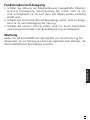
Bestimmungsgemäße Verwendung
Die Lichtschranke erfaßt berührungslos Gegenstände und Materialien
und meldet sie durch ein Schaltsignal.
Reichweite (r): siehe Typenschild.
Elektrischer Anschluß
Schalten Sie die Anlage spannungsfrei. Schließen Sie das Gerät
an (s. Seite 20 oder Typenschild).
Belastung des Funktionskontroll-Ausgangs (fc-output): max.
10mA.
Sichtbares Laserlicht; Laserschutzklasse 2.
Nicht in den Laserstrahl blicken!
Die beigelegten Aufkleber (Warnhinweis Laser) müssen
in unmittelbarer Nähe des Geräts angebracht werden.
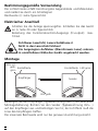
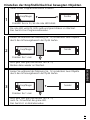
Montage
Befestigen Sie den Empfänger (Typbezeichnung OLE-..) mit Hilfe einer
Montagehalterung. Richten Sie den Sender (Typbezeichnung OLS-...)
auf den Empfänger aus und befestigen Sie ihn; der Lichtfleck muß die
Linse des Empfängers treffen.
Die maximale Reichweite wird nur bei genauer Ausrichtung erreicht.
2
LEDs rot,
gelb,
grün
LED gelb
Einstelltaste
Empfänger
Sender
LED grün
Einstelltaste

DEUTSCH
Befestigen Sie das Gerät so, daß sich die Einbaulage nicht verän-
dern kann (vermeiden Sie insbesondere starke Vibrationen!).
Lasergeräte mit sehr kleinem Lichtfleck-Durchmesser sind stark
fokussiert; geringste Veränderungen der Einbaulage können
daher zur Dejustage führen.
Justierhilfe
Der Sender hat zur Ausrichtung eine Justierhilfe integriert. Durch
Drücken des Einstelltaste am Sender wird die Intensität des Sendelichts
erhöht, so daß der Sendelichtfleck deutlich sichtbar ist. Nach erneutem
Drücken wird das Sendelicht wieder auf normale Intensität gesetzt.
Wird die Taste nicht ein zweites mal gedrückt, wird das Sendelicht
nach ca. 15 min. auf normale Intensität gesetzt.
Wichtig! Inbetriebnahme
Die Einweglichtschranke ist ohne weitere Einstellungen betriebsbereit
(plug and play) und auf max. Reichweite eingestellt. Dies bedeutet,
daß die Einweglichtschranke mit maximaler Betriebsreserve betrieben
wird. Die nachfolgend beschriebenen Einstellungen sind nur erforder-
lich wenn z.B. teiltransparente Objekte erfasst werden sollen.
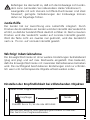
Einstellen der Empfindlichkeit bei stillstehenden Objekten
3
Drücken Sie ca. 2s, bis die rote LED blinkt.
Gerät in den Programmiermodus schalten.
Die rote LED verlischt; LEDs gelb und grün blinken im Wechsel.
Das Gerät ist im Programmiermodus.
1
Empfänger
Sender

Einstellungen 2 und 3 können auch in umgekehrter Reihenfolge erfolgen.
Ist die Einstellung der Empfindlichkeit nicht möglich (z. B. Hell-
signal und Dunkelsignal sind annähernd gleich stark) blinkt die
rote LED nach Schritt 3 für ca. 2s. Danach geht das Gerät mit
unveränderter Empfindlichkeit in den Betriebsmodus über.
Wird die Einstelltaste während der Programmierung 15 min.
nicht betätigt geht das Gerät automatisch mit unveränderter
Empfindlichkeit in den Betriebsmodus über.
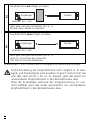
4
Drücken Sie 1 mal.
LEDs gelb und grün verlöschen für ca. 1s,
nach ca. 3s leuchtet die grüne LED.
Das Gerät ist im Betriebsmodus.
3
Empfindlichkeit ohne Objekt einstellen.
Empfänger
Sender
Empfindlichkeit mit Objekt einstellen.
Drücken Sie 1 mal.
LEDs gelb und grün verlöschen für ca. 1s,
blinken dann wieder im Wechsel.
2
Empfänger
Sender

DEUTSCH
Einstellen der Empfindlichkeit bei bewegten Objekten
5
Lassen Sie während der Messung (ca. 1s) mindestens zwei Objekte
durch den Erfassungsbereich der Optik laufen.
Drücken Sie 1 mal.
LEDs gelb und grün verlöschen für ca. 1s,
blinken dann wieder im Wechsel.
2
Drücken Sie 1 mal.
LEDs gelb und grün verlöschen für ca. 1s,
nach ca. 3s leuchtet die grüne LED.
Das Gerät ist im Betriebsmodus.
3
Lassen Sie während der Messung (ca. 1s) mindestens zwei Objekte
durch den Erfassungsbereich der Optik laufen.
Empfänger
Sender
Empfänger
Sender
Drücken Sie ca. 2s, bis die rote LED blinkt.
Gerät in den Programmiermodus schalten.
Die rote LED verlischt; LEDs gelb und grün blinken im Wechsel.
Das Gerät ist im Programmiermodus.
1
Empfänger
Sender

Ist die Einstellung der Empfindlichkeit nicht möglich (z. B. Hell-
signal und Dunkelsignal sind annähernd gleich stark) blinkt die
rote LED nach Schritt 3 für ca. 2s. Danach geht das Gerät mit
unveränderter Empfindlichkeit in den Betriebsmodus über.
Wird die Einstelltaste während der Programmierung 15 min.
nicht betätigt geht das Gerät automatisch mit unveränderter
Empfindlichkeit in den Betriebsmodus über.
Einstellen maximaler Empfindlichkeit
• Gehen Sie in den Programmiermodus (s. Schritt 1).
• Unterbrechen Sie den Lichtstrahl
• Drücken Sie 2 mal die Einstelltaste (s. Schritte 2 und 3).
Programmieren der Ausgangsfunktion
Betrieb
Prüfen Sie, ob das Gerät sicher funktioniert. Anzeige durch LEDs und
durch Funktionskontrollausgang.
6
Drücken Sie 10s lang.
Die rote LED beginnt nach 2s
schnell zu blinken. Danach blinken
die LEDs gelb und grün im Wechsel.
Nach 8s erlöschen alle LEDs, die
Ausgangsfunktion hat von Hell-
schaltend auf Dunkelschaltend
gewechselt (oder umgekehrt).
LED grün leuchtet Gerät ist betriebsbereit.
LED gelb leuchtet Ausgang ist geschaltet.
LEDs
gelb + rot
Blinken abwechselnd, 2 Hz: Ausgang kurzgeschlossen.
Blinken abwechselnd, 1 Hz: Interne Störung.
(Ausgang ist nicht geschaltet).
LED rot leuchtet
Störung bei der Objekterfassung, z. B. Dejustierung,
Verschmutzung der Linsen
Empfänger

DEUTSCH
Funktionskontroll-Ausgang
• Schaltet bei Störung der Objekterfassung (mangelhafte Objekter-
kennung, Dejustierung, Verschmutzung der Linsen) nach ca. 4s;
wird zurückgesetzt ca. 4s nach dem das Objekt wieder eindeutig
erfaßt wird.
• Schaltet bei Kurzschluß des Schaltausgangs sofort; wird zurückge-
setzt ca. 2s nach Beseitigung der Störung.
• Schaltet bei interner Störung sofort; wird nur durch Ausschalten
und erneutes Einschalten der Betriebsspannung zurückgesetzt.
Wartung
Halten Sie die Kunststofflinsen des Gerätes von Verschmutzung frei.
Verwenden Sie zur Reinigung keine Lösungsmittel oder Reiniger, die
die Kunststofflinsen beschädigen könnten.
7

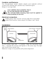
Function and features
The through-beam sensor detects objects and materials without
contact and indicates their presence by a switched signal.
Range (r): see type label.
Laser radiation; laser protection class 2.
Do not look directly into the beam!
The enclosed labels (warning laser) must be applied in
close proximity to the unit.
Electrical connection
Isolate power, then connect unit (see page 20 or type label).
Load of the function check output (fc output): max. 10mA.
Installation
Fix the receiver (type OLE-...) in position. Align the transmitter (type
OLS-...) towards the receiver and tighten in the same way. The light
spot must hit the receiver lens.
Maximum range is only possible with precise alignment.
8
LEDs red
yellow
green
LED yellow
push button
receiver
transmitter
LED green
push button

ENGLISH
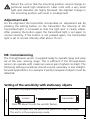
Mount the unit so that the mounting position cannot change (in
particular avoid high vibrations!). Laser units with a very small
light spot diameter are highly focussed; the slightest change in
the mounting position will result in misalignment.
Adjustment aid:
For the alignment the transmitter incorporates an adjustment aid. By
pressing the setting button on the transmitter the intensity of the
transmitted light is increased so that the light spot is clearly visible.
After pressing the button again the transmitted light is set again to
normal intensity. If the button is not pressed again, the transmitted
light is set to normal intensity after about 15 min.
NB: Commissioning
The through-beam sensor is supplied ready to operate (plug and play)
set at the max. sensing range. This is sufficient if the through-beam
sensor can operate with maximum excess gain (highest contrast). The
following setting procedures should only be necessary in less straight-
forward applications, for example if partly transparent objects must be
detected.
Setting of the sensitivity with stationary objects
9
Press for about 2s until the red LED flashes.
Activate the programming mode of the unit.
The red LED goes out; the yellow and green LEDs flash alternately.
The unit is in the programming mode.
1
receiver transmitter

You can also proceed in reverse order: first setting without the object, then with
the object.
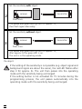
If the setting of the sensitivity is not possible (e.g. object signal and
background signal are about the same), the red LED flashes after
step 3 for approx. 2s. The unit then passes into the operating
mode with the sensitivity being unchanged.
If the setting button is not activated for 15 minutes during the
programming process, the unit passes automatically into the
operating mode with the sensitivity being unchanged.
10
Set the sensitivity with object.
Press once.
The yellow and green LEDs go out for approx. 1s,
then flash again alternately.
2
receiver transmitter
Press once.
The yellow and green LEDs go out for approx. 1s,
after approx 3s the green LED is on.
The unit is in the operating mode.
3
Set the sensitivity without object.
receiver transmitter

ENGLISH
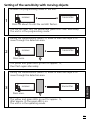
Setting of the sensitivity with moving objects
11
During the measurement (about 1s) allow at least two objects to
move through the detection area.
Press once.
The yellow and green LEDs go out for approx. 1s,
then flash again alternately.
2
Press once.
The yellow and green LEDs go out for approx. 1s,
after approx. 3s the green LED is on.
The unit is in the operating mode.
3
During the measurement (about 1s) allow at least two objects to
move through the detection area.
receiver transmitter
receiver
transmitter
Press for about 2s until the red LED flashes.
Activate the programming mode of the unit.
The red LED goes out; the yellow and green LEDs flash alternately.
The unit is in the programming mode.
1
receiver transmitter

If the setting of the sensitivity is not possible (e.g. object signal
and background signal are about the same), the red LED flashes
after step 3 for approx. 2s. The unit then passes into the operat-
ing mode with the sensitivity being unchanged.
If the setting button is not activated for 15 minutes during the
programming process, the unit passes automatically into the
operating mode with the sensitivity being unchanged.
Setting of the maximum sensitivity
• Go into the programming mode (step 1).
• Interrupt the light beam.
• Press the setting button twice (see steps 2 and 3).
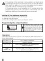
Programming the output function
Operation
Check the safe functioning of the unit. Display by LEDs and by the fun-
ction check output.
12
LED green is lit Unit is ready for operation.
LED yellow is lit Output is switched.
LEDs
yellow + red
Flash alternately, 2 Hz: output short-circuited.
Flash alternately, 1 Hz: internal malfunction
(output is not switched).
LED red is lit
Error in object detection, e.g. maladjustment,
soiling of the lenses.
Press for 10s.
The red LED starts to flash fast after
2s. Then the yellow and green LEDs
flash alternately. After 8s all LEDs go
off, the output function has chan-
ged from light-on mode to dark-on
mode (or vice versa).
receiver

ENGLISH
Function check output
• Switches in the case of incorrect object detection (error in object
detection, maladjustment, soiling of the lenses) after approx. 4 s, it
switches back approx. 4 s after the object is again correctly detect-
ed.
• Immediately switches in the case of a short circuit of the switching
output, it switches back approx. 2 s after the fault has been recti-
fied.
• Immediately switches in the case of an internal fault, it is only
switched back by turning off the operating voltage and then on
again.
Maintenance
Keep the plastic lenses of the sensor free from soiling.
For cleaning do not use any solvents or cleaning agents which could
damage the plastic lenses.
13

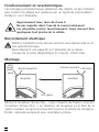
Fonctionnement et caractéristiques
Ces barrages photoélectriques détectent des objects et des matières
sans contact et indique leur présence par un signal de commutation.
Portée (r): voir l'étiquette.
Rayonnement laser; laser de classe 2.
Ne pas regarder dans l’axe de la source lumineuse!
Les étiquettes jointes (avertissement: laser) doivent être
appliquées tout proche de la cellule.
Raccordement électrique
Mettre l'installation hors tension avant le raccordement de la cel-
lule optoélectronique.
Raccordement: voir page 20 ou l'étiquette de la cellule.
Charge de la sortie diagnostique (fc output): 10mA maxi.
Montage
Monter le récepteur (forme OLE-...) avec l’équerre de fixation. Orienter
l’e´metteur (forme OLS-...) en direction du récepteur et le fixer de la
même manière. Le spot lumineux doit toucher la lentille du récepteur.
Portée optimale seulement avec orientation précise.
14
LED jaune
bouton-poussoir
récepteur
émetteur
LED verte
LEDs
rouge
jaune
verte
bouton-poussoir

FRANÇAIS
Monter la cellule afin que sa position de montage ne puisse pas
changer (éviter surtout des vibrations de forte intensité!). Les cel-
lules avec un très petit diamètre du spot lumineux sont forte-
ment focalisées; le plus faible changement de la position de
montage peut provoquer un désalignement.
Aide au réglage
Pour orienter la cellule, l’émetteur possède une aide de réglage. En
appuyant sur le bouton de réglagede l’émetteur l’intensité de la
lumière émise est augmentée jusqu’à ce que le spot lumière soit clai-
rement visible. En appuyant encore une fois la lumière émise est mise
de nouveau à l’intensité normale. Si le bouton-poussoir n’est pas
appuyé une deuxième fois la lumière émise est mise à l’intensité nor-
male après env. 15 min.
Important! Mise en service
Le barrage photoélectrique est disponible sans effectuer des réglages
(plug and play) et est réglée à la portée maxi. Cela signifie que le bar-
rage photoélectrique fonctionne avec une capacité de réserve maxi-
male. Les réglages décrits ci-dessous ne sont nécessaires que si, par
exemple, des objets partiellement transparents doivent être détectés.
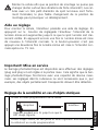
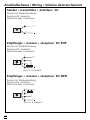
Réglage de la sensibilité en cas d’objets statiques
15
Appuyer pendant env. 2s jusqu’à ce que la
LED rouge clignote.
Activer le mode programmation de la cellule.
La LED rouge s’éteint, les LED jaune et verte clignotent alternativement.
La cellule est en mode programmation.
1
récepteur
émetteur

Vous pouvez également procéder dans l’ordre inverse: régler d’abord sans
objet, ensuite avec l’objet.
Si le réglage de la sensibilité n’est pas possible (p. ex. le signal de
l’objet et le signal de l’arrière-plan ont presque la même inten-
sité), la LED rouge clignote après l’étape 3 pendant env. 2s.
Ensuite la cellule passe au mode de fonctionnement sans chan-
ger la sensibilité.
Si le bouton-poussoir n'est pas appuyé pendant 15 minutes lors
de la programmation, la cellule passe automatiquement au
mode de fonctionnement sans changer la sensibilité.
16
Appuyer une fois.
Les LED jaune et verte s’éteignent pendant env. 1s,
après env. 3s la LED verte s’allume.
La cellule est réglée et elle est en mode fonctionnement.
3
Régler la sensibilité sans objet.
récepteur
émetteur
Régler la sensibilité avec l’objet.
Appuyer une fois.
Les LED jaune et verte s’éteignent pendant env. 1s,
ensuite elles clignotent de nouveau alternativement.
2
récepteur
émetteur

FRANÇAIS
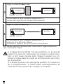
Réglage de la sensibilité en cas d’objets mobiles
17
Durant la mesure (env. 1s) laisser passer au moins deux objets à
travers la zone de détection de l’optique.
Appuyer une fois.
Les LED jaune et verte s’éteignent pendant env. 1s,
ensuite elles clignotent de nouveau alternativement.
2
Appuyer une fois.
Les LED jaune et verte s’éteignent pendant env. 1s,
après env. 3s la LED verte s’allume.
La cellule est réglée et elle est en mode fonctionnement.
3
Durant la mesure (env. 1s) laisser passer au moins deux objets à
travers la zone de détection de l’optique.
récepteur
émetteur
récepteur
émetteur
Appuyer pendant env. 2s jusqu’à ce que la LED
rouge clignote.
Activer le mode programmation de la cellule.
La LED rouge s’éteint, les LED jaune et verte clignotent alternativement.
La cellule est en mode programmation.
1
récepteur
émetteur

Si le réglage de la sensibilité n’est pas possible (p. ex. le signal de
l’objet et le signal de l’arrière-plan ont presque la même inten-
sité), la LED rouge clignote après l’étape 3 pendant env. 2s.
Ensuite la cellule passe au mode de fonctionnement sans chan-
ger la sensibilité.
Si le bouton-poussoir n'est pas appuyé pendant 15 minutes lors
de la programmation, la cellule passe automatiquement au
mode de fonctionnement sans changer la sensibilité.
Réglage de la sensibilité maximale
• Passer au mode programmation (étape 1).
• Interrompre le faisceau.
• Appuyer sur le bouton de réglage deux fois (voir étapes 2 et 3).
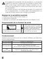
Programmation de la fonction de sortie
Fonctionnement
Vérifier le bon fonctionnement de la cellule. Indication par LED et par
la sortie diagnostique.
18
Appuyer pendant env. 10s jusqu'à
ce que toutes les LED s'éteignent.
La LED rouge commence à cligno-
ter rapidement après 2s. Ensuite les
LED jaune et verte clignotent alter-
nativement. Après 8s toutes les
LED s'éteignent, la sortie a changé
de NF à NO (ou vice versa).
LED verte allumée L’appareil est operationnel.
LED jaune allumée
La sortie est commutée.
LED
jaune + rouge
Clignotent altern., 2Hz: sortie en état de courts-circuits.
Clignotent alternativement, 1Hz: erreur interne
(sortie pas commutée).
LED rouge allumée
Erreur lors de la détection de l’objet,
par ex. mauvais réglage, encrassement des lentilles.
récepteur

FRANÇAIS
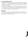
La sortie diagnostique
• Commute en cas d'erreur lors de la détection de l'objet (mauvaise
détection de l'objet, désalignement, encrassement des lentilles)
après env. 4s, est réinitialisée 4s après que l'objet est de nouveau
détecté correctement.
• Commute immédiatement en cas de court-circuit de la sortie de
commutation, est réinitialisée env. 2s après élimination de l'erreur.
• Commute en cas d'erreur interne, n'est réinitialisée que par la mise
hors tension et ensuite la mise sous tension.
Entretien
Les lentilles de la cellule doivent être dégagées de tout encrassement.
Pour le nettoyage ne pas utiliser de solvants ou de produits qui pour-
raient abîmer les lentilles en plastique.
19

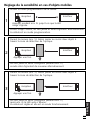
Anschlußschema / Wiring / Schéma de branchement
20
Sender • transmitter • émetteur DC
1
3
L
+
L
Sensor mit Steckverbindung
Sensor with connector
Détecteur avec connecteur
Empfänger • receiver • récepteur DC PNP
Empfänger
• receiver • récepteur DC NPN
L
L
+
3
2
4
1
L
L
+
3
4
2
1
Sensor mit Steckverbindung
Sensor with connector
Détecteur avec connecteur
Sensor mit Steckverbindung
Sensor with connector
Détecteur avec connecteur
Pin 2 = fc-output
Pin 2 = fc-output
-
 1
1
-
 2
2
-
 3
3
-
 4
4
-
 5
5
-
 6
6
-
 7
7
-
 8
8
-
 9
9
-
 10
10
-
 11
11
-
 12
12
-
 13
13
-
 14
14
-
 15
15
-
 16
16
-
 17
17
-
 18
18
-
 19
19
-
 20
20


IFM Electronic Efector 200 OL Series Operating Instructions Manual
- Taper
- Operating Instructions Manual
dans d''autres langues
- English: IFM Electronic Efector 200 OL Series
- Deutsch: IFM Electronic Efector 200 OL Series
Documents connexes

Autres documents
-
IFM OL0007 Mode d'emploi
-
-
-
-
-
-
-
-
 ModelCraft Phase3 10,5T Operating Instructions Manual
-
Arrma VORTEKS BLX 4X4 Le manuel du propriétaire
