
Aquam8012A/Aquam8512A Series Industrial
Ethernet Switches
Hardware Installation Manual
Publication Date: May. 2016
Version: V1.2
No.: 112023041

Aquam8012A/Aquam8512A Series
Industrial Ethernet Switches Hardware Installation Manual
Disclaimer:
Kyland Technology Co., Ltd. tries to keep the content
of this manual as accurate and as updated as possible. This
document is not guaranteed to be error-free, and we reserve the
right to amend it without notice to users.
All rights reserved. No part of this documentation may be excerpted,
reproduced, translated, annotated or duplicated, in any form or by
any means without the prior written permission of KYLAND Corporation.
Copyright © 2016 Kyland Technology Co., Ltd.

Notice for Safety Operation
The product performs reliably as long as it is used accord-
ing to the guidance. Artificial damage or destruction of the
device should be avoided. Before using the device, read
this manual carefully for personal and equipment safety.
Please keep the manual for further reference. Kyland is
not liable to any personal or equipment damage caused
by violation of this notice.
Do not place the device near water sources or damp areas. Keep
the ambient relative humidity within the range from 5% to 95%
(non-condensing).
Do not place the device in an environment with high magnetic field,
strong shock, or high temperature. Keep the working and storage
temperatures within the allowed range.
Install and place the device securely and firmly.
Please keep the device clean; if necessary, wipe it with a soft cotton
cloth.
Do not place any irrelevant materials on the device or cables. Ensure
adequate heat dissipation and tidy cable layout without knots.
Wear antistatic gloves or take other protective measures when
operating the device.
Avoid any exposed metal wires because they may be oxidized
or electrified.
Install the device in accordance with related national and local
regulations.
Before power-on, make sure the power supply is within the allowed
range of the device. High voltage may damage the device.
Power connectors and other connectors should be firmly interconnected.
Do not plug in or out the power supply with wet hands. When the device
is powered on, do not touch the device or any parts with wet hands.
Before operating a device connected to a power cable, remove all
jewelry (such as rings, bracelets, watches, and necklaces) or any
other metal objects, because they may cause electric shock or burns.
●
●
●
●
●
●
●
●
●
●
●
●

In the following cases, please immediately shut down
your power supply and contact your Kyland represen-
tative:
Do not operate the device or connect or disconnect cables during
an electrical storm.
Use compatible connectors and cables. If you are not sure, contact
our sales or technical support personnel for confirmation.
Do not disassemble the device by yourself. When an anomaly
occurs, contact our sales or technical support personnel.
If any part is lost, contact our sales or technical support personnel to
purchase the substitute. Do not purchase parts from other channels.
Dispose of the device in accordance with relevant national
provisions, preventing environmental pollution.
●
●
●
●
●
Water gets into the equipment.
Equipment damage or shell damage.
Equipment operation or performance has abnormally changed.
The equipment emits odor, smoke or abnormal noise.
●
●
●
●
The following information applies when operating this device in hazardous
locations:
Suitable for use in Class I, Division 2, Groups A, B, C and D Hazardous
Locations, or nonhazardous locations only.
Cet appareillage est utilisable dans les emplacements de Classe I, Division 2,
Groupes A, B, C et D, ou dans les emplacements non dangereux seulement.
WARNING: EXPLOSION HAZARD
● Do not disconnect equipment while the circuit is live or unless the area is
known to be free of ignitable concentrations.
● Substitution of any component may impair suitability for Class I, Division 2.
AVERTISSEMENT: RISQUE D'EXPLOSION
● Avant de deconnecter l'equipement, couper le courant ou s'assurer que
l'emplacement est designe non dangereux.
● La substitution de composants peut rendre ce materiel inacceptable pour les
emplacements de Classe I, Division 2.

Contents
1 Product Overview…………………………………………………… 1
2 Structure and Interface………………………………………………2
3 Mounting
………………………………………………………………
3
3.1 Dimension Drawing
……………………………………………
3
3.2 Mounting Modes and Steps
…………………………………
4
4 Connection
…… …… …… …… …… … …… …… … … … … … …
5
4.1 10/100Base-T(X) Ethernet Port
………………………………5
4.1.1 Functions
……………………………………………………
5
4.1.2 Pin Definitions and Wiring Sequence
……………………
5
4.2 10/100/1000Base-T(X) Ethernet Port
………………
…
… … 7
4.3 Console Port
…………………………………
…… … … …
…
10
4.4 Grounding
………………………………………………………
11
4.5 Power port
………………………………
…………
… … ……
11
4.6 Bypass Port
………………………………… ………… … … …
12
5 LEDs
…………………………………………………………………
13
6 Switch Access
………………………………
……………………
…
14
6.1 Access through Console Port
………………………………14
6.2 Access through Telnet
……………
…………………
………17
6.3 Access through Web
………………
………
…………………
17
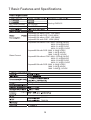
7 Basic Features and Specifications
…………………………………
18


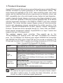
1 Product Overview
Aquam8012A/Aquam8512A includes a series of high-performance industrial Ethernet
switches developed by Kyland particularly for rail transportation industry. The
series devices are applicable to PIS, CCTV, video monitoring system, train control
system, and the industrial field with strict requirements on vibration, shock, and
EMC compatibility due to the solid closed housing, fanless but heat dissipation-
capable single-rib shaped chassis, overcurrent, overvoltage protection for power
input, sound EMC protection of M12 ports, and IP65 protection class. All the devices
meet the requirements stipulated in the EN50155, EN50121 and other industrial
standards. The series switches support Bypass power-off direct-connection
function and redundancy protocol, guaranteeing the reliable operation of the
system. Aquam8012A/Aquam8512A provides powerful network management
functions. The devices can be managed through CLI, Telnet, Web, and SNMP-
based network management software. Aquam8512A is a layer 3 switch that
supports the layer 3 routing protocol.
The switches support panel mounting. They provide up to four
10/100/1000Base-T(X) Ethernet ports, and eight 10/100Base-T(X) Ethernet
ports. The 10/100Base-T(X) Ethernet ports support IEEE802.3at (compatible
with IEEE802.3af) POE output. Each POE port can provide a maximum of 30
W feed and the entire PSE is capable of providing a maximum of 61.6 W feed.
1
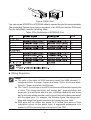
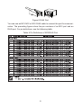
Table 1 Aquam8012A/Aquam8512A Models
Model Aquam8012A-Ports-PS1-PS2 Aquam8012A-B-Ports-PS1-PS2
Aquam8512A-Ports-PS1-PS2 Aquam8512A-B-Ports-PS1-PS2
Code definition Code option
Ports:
GE, T, P
Note:
3GE9P: three 10/100/1000Base-T(X) M12 ports; nine 10/100Base-
T(X) M12 POE ports.
PS1-PS2:
power input
Model without POE:
H6-H6(72/96/110VDC, redundant power input), L14-L14(48DC,
redundant power input), L13-L13(24DC, redundant power input)
Note:
We reserve the right to amend the product information listed in table 1
and table 2 without notice. To obtain the latest information, you can
contact our sales or technical support personnel.
B Support Bypass function
3GE9T, 3GE9P, 4GE8T, 4GE8P, 9T, 9P
3GE9T: three 10/100/1000Base-T(X) M12 ports; nine 10/100Base-
T(X) M12 ports.
Model with POE:
WV-WV(24-110VDC, redundant power input)

2
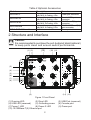
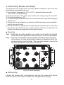
Figure 1 Front Panel
(1) Running LED (2) Ring LED (3) USB Port (reserved)
(4) USB LED (reserved) (5) Grounding screw (6) Console port
(7) Power 1 LED (8) Power 2 LED (9) Power port
(10) 10/100Base-T(X) Ethernet port
2 Structure and Interface
Caution:
It is recommended to purchase the port dustproof shield (optional)
to keep ports clean and ensure switch performance.
Table 2 Optional Accessories
Model Description Remarks
M12-A-4P-F Female cable connector
with M12, A-Coding, 4 Pin Power port connector
M12-A-4P-M Male cable connector
with M12, A-Coding, 4 Pin
Console/USB port
connector
M12-D-4P-M Male cable connector
with M12, D-Coding, 4 Pin
10/100Base-T(X) port
connector
M12-X-8Pin-M Male cable connector
with M12, X-Coding, 8 Pin
10/100/1000Base-T(X)
port connector
DT-XL-PWR-M12-xxx-3m
M12 to bare end cable Power port cable
(7)
(6)
(9)
(10)
(14) (13)
(11)
(8)
(1) (2 )
(3)
(4)
(5)
(12)

3
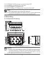
Figure 2 Dimensions(unit: mm)
163
142.3
6.5
3
111.7
78
100
56 100
3 Mounting
3.1 Dimension Drawing
Caution:
● As part of the heat dissipation system, the switch housing becomes
hot during operation. Please use caution when coming in contact
and avoid covering the switch housing when the switch is running.
● The figures in this manual are only for reference.
(11) 10/100Base-T(X) Ethernet port connection status LED
(12) 10/100Base-T(X) Ethernet Port POE LED
(13) 10/100/1000Base-T(X) Ethernet port
(14) 10/100/1000Base-T(X) Ethernet port connection status LED
Note:
Non-PoE products do not have PoE indicators.
For products that support the bypass function, the two gigabit ports
enclosed in the dashed lines are one pair of bypass ports.
●
●
177

4
Figure 3 Panel Mounting
● Dismounting
Loosen the screws with a screwdriver, remove the screws and device
from the wall or inner wall of a cabinet to complete dismounting.
3.2 Mounting Modes and Steps
The series devices support panel mounting. Before installation, make sure that
the following requirements are met.
1) Environment: temperature (-40
°C
to 70
°C
), ambient relative humidity
(5% to 95%, non-condensing).
2) Power requirement: The power input is within the voltage range of the switch.
3) Grounding resistance: <5
Ω
4) No direct sunlight, distant from heat source and areas with strong electromagnetic
interference.
5) Devices are to be installed in an authority certified enclosure and accessible
only by the use of a tool.
6) Devices should be installed and accessed by service personnel or users who
have been instructed about the reasons for the restrictions applied to the
location and about any precautions that shall be taken.
● Mounting
Step 1: Select the mounting position (on a wall or inner wall of a cabinet)
for the device and guarantee adequate space and heat dissipation.
Step 2: Punch four holes in the selected position according to the dimensions
of the device. Put the screw holes of device in alignment with the
corresponding punched holes. Then use four screws to secure the
device to the wall or inner wall of a cabinet.

5
10/100Base-T(X) port connector, 10/100/1000Base-T(X) port connector,
console port connector, USB port connector, power port connector, and power
port connection cable are all optional (For details, see Table 2 ). That is, these
components need to be purchased separately as required.
10/100Base-T(X) Ethernet port is equipped with M12 connector, which is
dustproof, waterproof, and anti-vibration. The port is self-adaptive. It can
automatically configure itself to work in 10M or 100M state, full or half duplex
mode. The port can also adapt to MDI or MDI-X connection automatically. You
can connect the port to a terminal or network device with a straight-through or
cross-over cable.
4 Connection
4.1 10/100Base-T(X) Ethernet Port
Figure 4 M12 Port (female)
● Pin Definition
4.1.1 Functions
● Data Transmission
Serving as the Power Sourcing Equipment (PSE), the switches can provide
power supply for PDs through 10/100Base-T(X) Ethernet ports. The
10/100Base-T(X) Ethernet ports support IEEE802.3at (compatible with
IEEE802.3af) POE output. Each POE port can provide a maximum of 30 W
feed and the entire PSE is capable of providing a maximum of 61.6 W feed.
1. POE Definition
POE indicates that the device can provide power supply for PDs through
Ethernet ports. The device supports a maximum distance of 100m for power
supply.
2. POE Power Supply
The device supports data wires to provide power supply for PDs.
● POE
4.1.2 Pin Definitions and Wiring Sequence

6
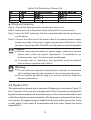
Table 3 Pin Definitions of M12/RJ45 Port
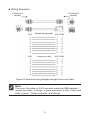
● Wiring Sequence
You can use an M12-M12 or M12-RJ45 cable to connect the port for communication.
The preceding figures show the pin numbers of an M12 port and an RJ45 port.
For pin definitions, see the following table.
11
88
Figure 5 RJ45 Port
Note:
The color of the cable for RJ45 connector meets the 568B standard: 1-
orange and white, 2-orange, 3-green and white, 4-blue, 5-blue and white,
6-green, 7-brown and white, and 8-brown.
The 1 and 3, 2 and 4 pins on the M12 interface are differentiated signal pins
in pairs. The orange-and-white and orange pair, green-and-white and
green pair, blue-and-white and blue pair, and brown-and-white and brown
pair in twist pair cables must be used in correct pairs while being connected
with the signal pins. For example, the following figure, the orange-and-
white and orange and green-and-white and green pairs are used.
POE ports will not deliver any power for a certain time when a 10ms
interruption occurs on the power input. A suggested workaround is to
connect a UPS to prevent power interruption of the PSE.
●
●
●
POE
V+
V-
V+
V-

7
10/100/1000Base-T(X) Ethernet port is equipped with M12 connector, which is
dustproof, waterproof, and anti-vibration. The port is self-adaptive. It can
automatically configure itself to work in 10M or 100M state, full or half duplex
mode. The port can also adapt to MDI or MDI-X connection automatically. You
can connect the port to a terminal or network device with a straight-through or
cross-over cable.
4.2 10/100/1000Base-T(X) Ethernet Port
Figure 7 M12 Port (female)
● Pin Definition
Figure 6 Connection Using Straight-through/Cross-over Cable
Facing the A
direction
Facing the B
direction
2
3
1
4
2
3
1
4
1 8
M12 Straight-through cable
Cross-over cable
Orange and White
Orange and White
Orange
Orange
Green and White
Green and White
Green
Green
1
2
3
4
1
2
3
4
1
3
2
6
1
2
3
4
2
1
4
3
3
1
6
2
M12 RJ45

8
You can use an M12-M12 or M12-RJ45 cable to connect the port for communi-
cation. The preceding figures show the pin numbers of an M12 port and an
RJ45 port. For pin definitions, see the following table.
Table 4 Pin Definitions of M12/RJ45 Port
Figure 8 RJ45 Port
11
88

9
Figure 9 Connection Using Straight-through/Cross-over Cable
● Wiring Sequence
M12
1
2
3
4
5
6
7
8
1
2
3
4
5
6
7
8
1
2
3
6
4
5
7
8
1
2
3
4
5
6
7
8
3
4
1
2
7
8
5
6
3
6
1
2
7
8
4
5
M12 RJ45
M12 M12 RJ45
1 8
1
3
4
5
678
2
1
3
4
5
678
2
Facing the A
direction
Facing the B
direction
Straight-through cable
Cross-over cable
Note:
The color of the cable for RJ45 connector meets the 568B standard: 1-
orange and white, 2-orange, 3-green and white, 4-blue, 5-blue and
white, 6-green, 7-brown and white, and 8-brown.

10
One end of the M12-DB9 cable is an M12 connector to be inserted into the
console port of the device, and the other end is the DB9 connector to be
inserted into the 9-pin serial port of a PC.
Figure 10 Console Port (female)
Figure11 Wiring Sequence M12-DB9 Console Cable
Table 5 Pin Definition of DB9 Port (9-Pin Serial Port) and M12 Port (Console Port)
There is a console port on the front panel. The port is equipped with M12
connector. Connect the console port of the switch to the 9-pin serial port of a
PC with an M12-DB9 console cable. You can configure, maintain, and manage
the switch by running Hyper Terminal in Windows OS of a computer.
4.3 Console Port
9
5
DB9
2
3
5
2
1
3
M12
1
1
2
3 4
6
● M12-DB9 Console Cable
Facing the A
direction
Facing the B
direction
Wiring sequence

11
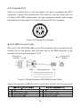
4.4 Grounding
Grounding protects the device from lightning and interference. Therefore, you
must ground the device properly.You need to ground the device before it is
powered on and disconnect the grounding cable after the device is powered
off. There is a grounding screw (see Figure 1) on the front panel of the device.
The screw is for chassis grounding. After crimping one end of the grounding
cable to a cold pressed terminal, secure the end of the grounding cable to the
grounding screw and firmly connect the other end to ground.
4.5 Power port
There is a power port on the front panel of the device. You need to connect the power
cable to the power port to provide power to the device. Power port is equipped
with M12 connector, which is dustproof, waterproof, and anti-vibration.The
device supports redundant power input, when one power input is faulty, the
device can continue operating properly, thereby improving network reliability.
Note:
Cross-sectional area of the chassis grounding cable>2.5mm
2
;
Grounding resistance<5Ω.
Note:
● 0.75mm
2
<Cross-sectional area of the power cable<2.5mm
2
;
grounding resistance<5Ω.
● It is supplied with required DC power by the engine and is not directly
connected to the public power grid.
Figure 12 Power Port (male)
● Pin Definition

12
Step 1: Ground the device properly according to section 4.4.
Step 2: Insert one end of the power cable into the M12 connector firmly.
Step 3: Insert the M12 connector with the connected cable into the power port
on the device.
Step 4: Connect the other end of the power cable to an external power supply
system according to the power supply requirements of the device. View
the status of the power LED. If the LED is on, the power is connected properly.
Table 6 Pin Definitions of Power Port
● Wiring and Mounting
Caution:
Warning:
Before connecting the device to power supply, make sure that the
power input meets the power requirement. If connected to an
incorrect power input, the device may be damaged.
To comply with UL restrictions, this equipment must be powered
from a source compliant with Class 2.
●
●
Do not touch any exposed conducting wire, terminal, or component
with a voltage warning sign, because it may cause personal injury.
Do not remove any part or plug in or out any connector when the
device is powered on.
●
●
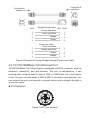
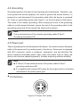
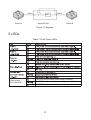
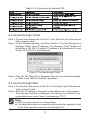
4.6 Bypass Port
The series switches provide one or two pairs of Bypass ports, as shown in Figure 13,
port 11 and port 12 are one pair of bypass ports. When the power is interrupted, the
bypass function is enabled, the relay switch jumps to the 2 state so that switch A and
switch B are directly connected physically. After the power is restored and the device
runs properly, the bypass function is disabled and the relay switch jumps to the 1 state
so that switch A and switch B communicate with each other through the switch
Aquam8512A.

13
5 LEDs
Table 7 Front Panel LEDs
Figure 13 Bypass
Port11 1
2
MAC
Switch A Switch BAquam8512A
Port12
Ethernet port
POE LED-POE
The POE port provides power supply normally
The POE port provides power supply abnormally
The POE port provides no power supply

14
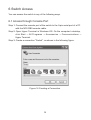
6 Switch Access
You can access the switch in any of the following ways.
6.1 Access through Console Port
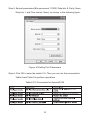
Figure 14 Creating a Connection
Step 1: Connect the console port of the switch to the 9-pin serial port of a PC
with the M12-DB9 console cable.
Step 2: Open Hyper Terminal in Windows OS. On the computer’s desktop,
click Start → All Programs → Accessories → Communications →
Hyper Terminal.
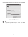
Step 3: Create a connection "Switch", as shown in the following figure.
La page est en cours de chargement...
La page est en cours de chargement...
La page est en cours de chargement...
La page est en cours de chargement...
La page est en cours de chargement...
La page est en cours de chargement...
La page est en cours de chargement...
La page est en cours de chargement...
-
 1
1
-
 2
2
-
 3
3
-
 4
4
-
 5
5
-
 6
6
-
 7
7
-
 8
8
-
 9
9
-
 10
10
-
 11
11
-
 12
12
-
 13
13
-
 14
14
-
 15
15
-
 16
16
-
 17
17
-
 18
18
-
 19
19
-
 20
20
-
 21
21
-
 22
22
-
 23
23
-
 24
24
-
 25
25
-
 26
26
-
 27
27
-
 28
28


KYLAND Aquam8012A Guide d'installation
- Taper
- Guide d'installation
- Ce manuel convient également à
dans d''autres langues
- English: KYLAND Aquam8012A Installation guide