Samsung DV42H5200GP/A3 Manuel utilisateur
- Catégorie
- Sèche-linge
- Taper
- Manuel utilisateur

DV42H5400*
DV42H5200*
DV42H5000*
Gas and Electric Dryer
User manual
Imagine the possibilities
Thank you for purchasing this Samsung product.
DV5000H_DC68-03381A-15_EN.indd 1 2019-06-03 12:29:42

English - 2
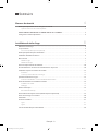
Contents
Safety instructions 4
What you need to know about safety instructions . . . . . . . . . . . . . . . . . . . . . . . . . . . . . . . . . . . . . . . . . . . . . . . . . . . . . 4
Important safety symbols and precautions . . . . . . . . . . . . . . . . . . . . . . . . . . . . . . . . . . . . . . . . . . . . . . . . . . . . . . . . . . . . . .4
CALIFORNIA PROPOSITION 65 WARNING . . . . . . . . . . . . . . . . . . . . . . . . . . . . . . . . . . . . . . . . . . . . . . . . . . . . . . . . . . . . . . 5
Important safety instructions . . . . . . . . . . . . . . . . . . . . . . . . . . . . . . . . . . . . . . . . . . . . . . . . . . . . . . . . . . . . . . . . . . . . . . . . . 6
Installing your dryer 8
Unpacking your dryer . . . . . . . . . . . . . . . . . . . . . . . . . . . . . . . . . . . . . . . . . . . . . . . . . . . . . . . . . . . . . . . . . . . . . . . . . . . . . . . . 8
What’s included . . . . . . . . . . . . . . . . . . . . . . . . . . . . . . . . . . . . . . . . . . . . . . . . . . . . . . . . . . . . . . . . . . . . . . . . . . . . . . . . . . . . . . 8
Accessories (Steam model only) . . . . . . . . . . . . . . . . . . . . . . . . . . . . . . . . . . . . . . . . . . . . . . . . . . . . . . . . . . . . . . . . . . . . . . . . .9
Important to installer . . . . . . . . . . . . . . . . . . . . . . . . . . . . . . . . . . . . . . . . . . . . . . . . . . . . . . . . . . . . . . . . . . . . . . . . . . . . . . . . . 9
Basic requirements . . . . . . . . . . . . . . . . . . . . . . . . . . . . . . . . . . . . . . . . . . . . . . . . . . . . . . . . . . . . . . . . . . . . . . . . . . . . . . . . . . . 9
Grounding . . . . . . . . . . . . . . . . . . . . . . . . . . . . . . . . . . . . . . . . . . . . . . . . . . . . . . . . . . . . . . . . . . . . . . . . . . . . . . . . . . . . . . . . . . . 9
Gas models . . . . . . . . . . . . . . . . . . . . . . . . . . . . . . . . . . . . . . . . . . . . . . . . . . . . . . . . . . . . . . . . . . . . . . . . . . . . . . . . . . . . . . . . . . . . .9
Electric models . . . . . . . . . . . . . . . . . . . . . . . . . . . . . . . . . . . . . . . . . . . . . . . . . . . . . . . . . . . . . . . . . . . . . . . . . . . . . . . . . . . . . . . . . .9
Location considerations . . . . . . . . . . . . . . . . . . . . . . . . . . . . . . . . . . . . . . . . . . . . . . . . . . . . . . . . . . . . . . . . . . . . . . . . . . . . . 10
Alcove or closet installations . . . . . . . . . . . . . . . . . . . . . . . . . . . . . . . . . . . . . . . . . . . . . . . . . . . . . . . . . . . . . . . . . . . . . . . . . 10
Ducting requirements . . . . . . . . . . . . . . . . . . . . . . . . . . . . . . . . . . . . . . . . . . . . . . . . . . . . . . . . . . . . . . . . . . . . . . . . . . . . . . . 12
Exhausting . . . . . . . . . . . . . . . . . . . . . . . . . . . . . . . . . . . . . . . . . . . . . . . . . . . . . . . . . . . . . . . . . . . . . . . . . . . . . . . . . . . . . . . . . . . . 13
Dryer exhaust tips . . . . . . . . . . . . . . . . . . . . . . . . . . . . . . . . . . . . . . . . . . . . . . . . . . . . . . . . . . . . . . . . . . . . . . . . . . . . . . . . . . . . . 14
Gas requirements . . . . . . . . . . . . . . . . . . . . . . . . . . . . . . . . . . . . . . . . . . . . . . . . . . . . . . . . . . . . . . . . . . . . . . . . . . . . . . . . . . . . 15
Commonwealth of massachusetts installation instructions . . . . . . . . . . . . . . . . . . . . . . . . . . . . . . . . . . . . . . . . . . . . 15
Exhaust ducting guide . . . . . . . . . . . . . . . . . . . . . . . . . . . . . . . . . . . . . . . . . . . . . . . . . . . . . . . . . . . . . . . . . . . . . . . . . . . . . . . 16
Ducting . . . . . . . . . . . . . . . . . . . . . . . . . . . . . . . . . . . . . . . . . . . . . . . . . . . . . . . . . . . . . . . . . . . . . . . . . . . . . . . . . . . . . . . . . . . . . . . 16
Cleaning . . . . . . . . . . . . . . . . . . . . . . . . . . . . . . . . . . . . . . . . . . . . . . . . . . . . . . . . . . . . . . . . . . . . . . . . . . . . . . . . . . . . . . . . . . . . . . 16
Electrical requirements . . . . . . . . . . . . . . . . . . . . . . . . . . . . . . . . . . . . . . . . . . . . . . . . . . . . . . . . . . . . . . . . . . . . . . . . . . . . . . 16
Electrical connections . . . . . . . . . . . . . . . . . . . . . . . . . . . . . . . . . . . . . . . . . . . . . . . . . . . . . . . . . . . . . . . . . . . . . . . . . . . . . . . . . 17
Connecting the inlet hose (Steam model only) . . . . . . . . . . . . . . . . . . . . . . . . . . . . . . . . . . . . . . . . . . . . . . . . . . . . . . . . 19
Replacement parts and accessories . . . . . . . . . . . . . . . . . . . . . . . . . . . . . . . . . . . . . . . . . . . . . . . . . . . . . . . . . . . . . . . . . . 20
Installation . . . . . . . . . . . . . . . . . . . . . . . . . . . . . . . . . . . . . . . . . . . . . . . . . . . . . . . . . . . . . . . . . . . . . . . . . . . . . . . . . . . . . . . . . . 20
Door reversal . . . . . . . . . . . . . . . . . . . . . . . . . . . . . . . . . . . . . . . . . . . . . . . . . . . . . . . . . . . . . . . . . . . . . . . . . . . . . . . . . . . . . . . . 21
Type 1 . . . . . . . . . . . . . . . . . . . . . . . . . . . . . . . . . . . . . . . . . . . . . . . . . . . . . . . . . . . . . . . . . . . . . . . . . . . . . . . . . . . . . . . . . . . . . . . . 21
Type 2 . . . . . . . . . . . . . . . . . . . . . . . . . . . . . . . . . . . . . . . . . . . . . . . . . . . . . . . . . . . . . . . . . . . . . . . . . . . . . . . . . . . . . . . . . . . . . . . . 22
Final installation checklist . . . . . . . . . . . . . . . . . . . . . . . . . . . . . . . . . . . . . . . . . . . . . . . . . . . . . . . . . . . . . . . . . . . . . . . . . . . . 24
DV5000H_DC68-03381A-15_EN.indd 2 2019-06-03 12:29:42

English - 3
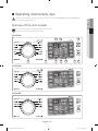
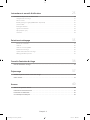
Operating instructions, tips 25
Overview of the control panel . . . . . . . . . . . . . . . . . . . . . . . . . . . . . . . . . . . . . . . . . . . . . . . . . . . . . . . . . . . . . . . . . . . . . . . . 25
Load the dryer properly . . . . . . . . . . . . . . . . . . . . . . . . . . . . . . . . . . . . . . . . . . . . . . . . . . . . . . . . . . . . . . . . . . . . . . . . . . . . . . . 29
Getting started . . . . . . . . . . . . . . . . . . . . . . . . . . . . . . . . . . . . . . . . . . . . . . . . . . . . . . . . . . . . . . . . . . . . . . . . . . . . . . . . . . . . . . . . 29
Rack dry (DV42H5400* Only) . . . . . . . . . . . . . . . . . . . . . . . . . . . . . . . . . . . . . . . . . . . . . . . . . . . . . . . . . . . . . . . . . . . . . . . . . . 31
Child Lock . . . . . . . . . . . . . . . . . . . . . . . . . . . . . . . . . . . . . . . . . . . . . . . . . . . . . . . . . . . . . . . . . . . . . . . . . . . . . . . . . . . . . . . . . . . . . 32
Drum Light . . . . . . . . . . . . . . . . . . . . . . . . . . . . . . . . . . . . . . . . . . . . . . . . . . . . . . . . . . . . . . . . . . . . . . . . . . . . . . . . . . . . . . . . . . . 32
Sound Off . . . . . . . . . . . . . . . . . . . . . . . . . . . . . . . . . . . . . . . . . . . . . . . . . . . . . . . . . . . . . . . . . . . . . . . . . . . . . . . . . . . . . . . . . . . . . 32
My Cycle . . . . . . . . . . . . . . . . . . . . . . . . . . . . . . . . . . . . . . . . . . . . . . . . . . . . . . . . . . . . . . . . . . . . . . . . . . . . . . . . . . . . . . . . . . . . . . 33
Smart Care . . . . . . . . . . . . . . . . . . . . . . . . . . . . . . . . . . . . . . . . . . . . . . . . . . . . . . . . . . . . . . . . . . . . . . . . . . . . . . . . . . . . . . . . . . . . 33
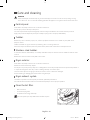
Care and cleaning 34
Control panel . . . . . . . . . . . . . . . . . . . . . . . . . . . . . . . . . . . . . . . . . . . . . . . . . . . . . . . . . . . . . . . . . . . . . . . . . . . . . . . . . . . . . . . . . 34
Tumbler . . . . . . . . . . . . . . . . . . . . . . . . . . . . . . . . . . . . . . . . . . . . . . . . . . . . . . . . . . . . . . . . . . . . . . . . . . . . . . . . . . . . . . . . . . . . . . . 34
Stainless steel tumbler . . . . . . . . . . . . . . . . . . . . . . . . . . . . . . . . . . . . . . . . . . . . . . . . . . . . . . . . . . . . . . . . . . . . . . . . . . . . . . . . 34
Dryer exterior . . . . . . . . . . . . . . . . . . . . . . . . . . . . . . . . . . . . . . . . . . . . . . . . . . . . . . . . . . . . . . . . . . . . . . . . . . . . . . . . . . . . . . . . . 34
Dryer exhaust system . . . . . . . . . . . . . . . . . . . . . . . . . . . . . . . . . . . . . . . . . . . . . . . . . . . . . . . . . . . . . . . . . . . . . . . . . . . . . . . . . 34
Clean the lint filter . . . . . . . . . . . . . . . . . . . . . . . . . . . . . . . . . . . . . . . . . . . . . . . . . . . . . . . . . . . . . . . . . . . . . . . . . . . . . . . . . . . . 34
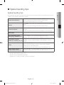
Special laundry tips 35
Special laundry tips . . . . . . . . . . . . . . . . . . . . . . . . . . . . . . . . . . . . . . . . . . . . . . . . . . . . . . . . . . . . . . . . . . . . . . . . . . . . . . . . . . 35
Troubleshooting 36
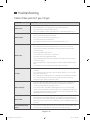
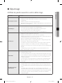
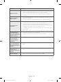
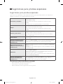
Check these points if your dryer… . . . . . . . . . . . . . . . . . . . . . . . . . . . . . . . . . . . . . . . . . . . . . . . . . . . . . . . . . . . . . . . . . . . 36
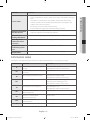
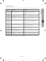
Information codes . . . . . . . . . . . . . . . . . . . . . . . . . . . . . . . . . . . . . . . . . . . . . . . . . . . . . . . . . . . . . . . . . . . . . . . . . . . . . . . . . . . 37
Appendix 38
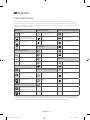
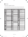
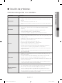
Fabric care chart . . . . . . . . . . . . . . . . . . . . . . . . . . . . . . . . . . . . . . . . . . . . . . . . . . . . . . . . . . . . . . . . . . . . . . . . . . . . . . . . . . . . . 38
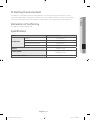
Protecting the environment. . . . . . . . . . . . . . . . . . . . . . . . . . . . . . . . . . . . . . . . . . . . . . . . . . . . . . . . . . . . . . . . . . . . . . . . . . 39
Declaration of conformity . . . . . . . . . . . . . . . . . . . . . . . . . . . . . . . . . . . . . . . . . . . . . . . . . . . . . . . . . . . . . . . . . . . . . . . . . . . . 39
Specications . . . . . . . . . . . . . . . . . . . . . . . . . . . . . . . . . . . . . . . . . . . . . . . . . . . . . . . . . . . . . . . . . . . . . . . . . . . . . . . . . . . . . . . 39
DV5000H_DC68-03381A-15_EN.indd 3 2019-06-03 12:29:42

English - 4
SAVE THESE INSTRUCTIONS
Safety instructions
Congratulations on your new Samsung Dryer. This manual contains important information on the installation, use,
and care of your appliance. Please take the time to read this manual to take full advantage of your dryer’s many
benefits and features.
What you need to know about safety instructions
Please read this manual thoroughly to ensure that you know how to operate the extensive features and functions
of your new appliance safely and efficiently. Retain the manual in a safe place near the appliance for future
reference. Use this appliance only for its intended purpose as described in this instruction manual. The Warnings
and Important Safety Instructions in this manual do not cover all possible conditions and situations that may
occur. It is your responsibility to use common sense, caution, and care when installing, maintaining, or operating
your dryer.
Always contact your manufacturer about problems or conditions you do not understand.
Important safety symbols and precautions
WARNING: Hazards or unsafe practices that may result in severe physical injury, death and/or
property damage.
Follow the information in this manual to minimize the risk of fire or explosion or to prevent property
damage, personal injury, or death.
CAUTION: Hazards or unsafe practices that may result in physical injury and/or property damage.
NOTE
These warning signs are here to prevent injury to you and others.
Please follow them explicitly.
After reading this section, keep it in a safe place for future reference.
DV5000H_DC68-03381A-15_EN.indd 4 2019-06-03 12:29:42

English - 5
01 SAFETY INSTRUCTIONS
SAVE THESE INSTRUCTIONS
CALIFORNIA PROPOSITION 65 WARNING
WARNING
Cancer and Reproductive Harm - www.P65Warnings.ca.gov.
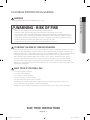
WARNING - RISK OF FIRE
• Clothes dryer installation must be performed by a qualified installer.
• Install the clothes dryer according to the manufacturer’s instructions and local codes.
• Do not install a clothes dryer with flexible plastic venting materials. If flexible metal (foil type) duct is
installed, it must be of a specific type identified by the appliance manufacturer as suitable for use with
clothes dryers. Flexible venting materials are known to collapse, be easily crushed, and trap lint. These
conditions will obstruct clothes dryer airflow and increase the risk of fire.
• To reduce the risk of severe injury or death, follow all installation instructions.
TO REDUCE THE RISK OF FIRE OR EXPLOSION:
• Do not dry items that have been previously cleaned, washed, soaked, or spotted with gasoline, dry cleaning
solvents, or other flammable or explosive substances. They emit vapors that could ignite or explode. Any
material that has been in contact with a cleaning solvent or flammable liquids or solids should not be placed
in the dryer until all traces of these flammable liquids or solids and their fumes have been removed.
There are many highly flammable items used in homes, such as acetone, denatured alcohol, gasoline,
kerosene, some liquid household cleaners, some spot removers, turpentine, waxes, and wax removers.
• Do not dry items containing foam rubber (may be labeled latex foam) or similarly textured rubber-like
materials on a heat setting. Heated foam rubber materials can, under certain circumstances, produce fire by
spontaneous combustion.
WHAT TO DO IF YOU SMELL GAS:
• Do not try to light any appliance.
• Do not turn on the appliance.
• Do not touch any electrical switch.
• Do not use any phone in your building.
• Clear the room, building or area of all occupants.
• Immediately call your gas supplier from a neighbor’s phone. Follow the gas supplier’s instructions.
• If you cannot reach your gas supplier, call the fire department.
• Installation and service must be performed by a qualified installer, service agency, or the gas supplier.
DV5000H_DC68-03381A-15_EN.indd 5 2019-06-03 12:29:42

English - 6
SAVE THESE INSTRUCTIONS
Important safety instructions
WARNING
To reduce the risk of fire, electric shock, or injury to persons when using your appliance, follow basic
precautions, including the following:
1. Read all instructions before using this appliance.
2. Do not dry articles that have been previously cleaned in, washed in, soaked in, or spotted with gasoline, dry-
cleaning solvents, or other flammable or explosive substances, as they give off vapors that could ignite or explode.
3. Do not use the dryer to dry clothes which have traces of any flammable substance, such as vegetable oil, cooking
oil, machine oil, flammable chemicals, paint thinner, etc., or anything containing wax or chemicals, such as mops
and cleaning cloths. Flammable substances may cause the fabric to catch fire by itself.
4. Do not store or use gasoline or other flammable vapors and liquids near this or any other appliance.
5. Do not allow children to play on or in the appliance. Close supervision of children is necessary when the appliance
is used near children.
6. Before the appliance is removed from service or discarded, remove the door to the drying compartment.
7. Do not reach into the appliance if the drum is moving.
8. Do not install or store this appliance where it will be exposed to the weather.
9. Do not tamper with internal controls.
10. Do not repair or replace any part of the appliance or attempt any service unless specifically recommended in the
user-maintenance instructions or in published user-repair instructions that you understand and have the skills to
carry out.
11. Do not use fabric softeners or products to eliminate static unless recommended by the manufacturer of the fabric
softener or product.
12. Clean the lint screen before or after each load.
13. Do not use heat to dry articles containing foam rubber or similarly textured rubber-like materials.
14. Keep area around the exhaust opening and adjacent surrounding areas free from the accumulation of lint, dust,
and dirt.
15. The interior of the appliance and exhaust duct should be cleaned periodically by qualified service personnel.
16. Do not place items exposed to cooking oils in your dryer. Items contaminated with cooking oils may contribute to
a chemical reaction that could cause a load to catch fire. To reduce the risk of fire due to contaminated loads, the
final part of a tumble dryer cycle occurs without heat (cool down period). Avoid stopping a tumble dryer before
the end of the drying cycle unless all items are quickly removed and spread out so that the heat is dissipated.
17. This appliance must be grounded. See “Electrical requirements” and “Grounding” in “Installing your dryer”
section.
18. Do not allow children to play on or in the appliance. Close supervision of children is necessary when the appliance
is used near children.
19. Do not insert your hand under the dryer.
• This may result in injury.
20. Take care that children’s fingers are not caught in the door when closing it.
• This may result in injury.
21. Control board and inlet valve are intentionally not grounded and may present a risk of electric shock only during
servicing.
• Do not contact this part while appliance is energized.
DV5000H_DC68-03381A-15_EN.indd 6 2019-06-03 12:29:42

English - 7
01 SAFETY INSTRUCTIONS
SAVE THESE INSTRUCTIONS
CAUTION
1. Do not sit on top of the dryer.
2. Because of continuing product improvements, Samsung reserves the right to change specifications without
notice. For complete details, see the Installation Instructions packed with your product before selecting
cabinetry, making cutouts, or beginning installation.
3. Do not wash clothing with large buckles, buttons, or other heavy metal or solid things.
4. Install and use in accordance with the manufacturer’s instructions.
5. All washed and unwashed fabrics that contain vegetable oil or cooking oil can be dangerous. Washing these
items in hot water with extra detergent will reduce, but not eliminate, the hazard. Always use the Cool Down
cycle for these items to reduce their temperature. Never remove these items from the dryer hot or interrupt
the drying cycle until the items have run through the Cool Down cycle. Never pile or stack these items when
they are hot.
6. Take care that children’s fingers are not caught in the door when closing it. This may result in injury.
DV5000H_DC68-03381A-15_EN.indd 7 2019-06-03 12:29:43

English - 8
Installing your dryer
Unpacking your dryer
Unpack your Dryer and inspect it for shipping damage. Make sure you have received all the items shown below. If
your Dryer was damaged during shipping, or you do not have all the items, contact 1-800-SAMSUNG (726-7864).
WARNING
Certain internal parts are intentionally not grounded and may present a risk of electric shock only during servicing.
Service Personnel - Do not contact the following parts while the appliance is energized: Control board and inlet valve.
WARNING
• The packing materials can be dangerous to children. Keep all packaging material (plastic bags,
polystyrene, etc.) well out of the reach of children.
• To prevent personal injury or strain, wear protective gloves whenever lifting or carrying the unit.
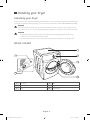
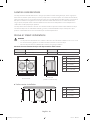
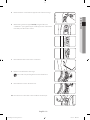
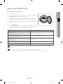
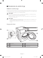
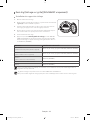
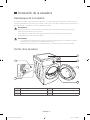
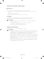
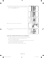
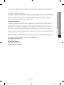
What’s included
5
6
1
2
4
3
1 Top cover 4 Filter
2 Control panel 5 Water Inlet (Steam model only)
3 Door 6 Duct Exhaust
DV5000H_DC68-03381A-15_EN.indd 8 2019-06-03 12:29:43

English - 9
02 INSTALLATION
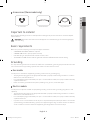
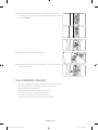
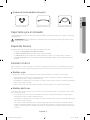
Accessories (Steam model only)
“Y”-connector Short inlet hose Long inlet hose
Important to installer
Please read the following instructions carefully before installing the dryer. These instructions should be kept for
future reference.
WARNING: Remove the door from all discarded appliances to avoid the danger of a child being trapped
and suffocating.
Basic requirements
Make sure you have everything necessary for the proper installation
• A GROUNDED ELECTRICAL OUTLET is required.
• A POWER CORD electric dryer (except for Canada).
• GAS LINES (if a gas dryer) must meet national and local codes.
• The EXHAUST SYSTEM must be made of rigid metal or flexible stiff-walled metal exhaust ducting.
Grounding
This dryer must be grounded. In the event of a malfunction or breakdown, grounding the product will reduce the
risk of electrical shock by providing a path of least resistance for the electrical current.
Gas models
Your dryer has a cord with an equipment-grounding conductor and a grounding plug.
• The plug must be plugged into an appropriate outlet that is properly installed and grounded in accordance
with all local codes and ordinances.
• Do not modify the plug provided with your dryer – if it doesn’t fit the outlet, have a proper outlet installed by
a qualified electrician.
• Never connect the ground wire to the plastic plumbing lines, gas lines, or hot water pipes.
Electric models
Your dryer has an optional cord with an equipment-grounding conductor and a grounding plug, which is sold
separately.
• The plug must be plugged into an appropriate outlet that is properly installed and grounded in accordance
with all local codes and ordinances.
• Do not modify the plug provided with your dryer – if it doesn’t fit the outlet, have a proper outlet installed by
a qualified electrician.
• If a power cord is not used and the electric dryer is to be permanently wired, the dryer must be connected to
a permanently grounded metal wiring system, or an equipment grounding conductor must be run with the
circuit conductors and connected to the equipment grounding terminal or lead on the dryer.
DV5000H_DC68-03381A-15_EN.indd 9 2019-06-03 12:29:44

English - 10
Location considerations
The dryer should be located where there is enough space at the front for loading the dryer, and enough space
behind for the exhaust system. This dryer is factory-ready for the rear exhaust option. To exhaust out the bottom,
right or the left, use the accessory exhaust kit. Instructions are included with the kit. Make sure the room in which
the dryer is located has enough fresh air. The dryer must be located where there are no air-flow obstructions.
For gas dryers, adequate clearance must be maintained as noted on the data plate to ensure adequate air for
combustion and the proper dryer operation.
The dryer must not be installed or stored in an area where it will be exposed to water and/or weather. The dryer
area must be kept clear of combustible materials, gasoline, and other flammable vapors and liquids. A dryer
produces combustible lint. The area around the dryer should be kept lint-free.
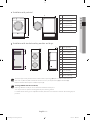
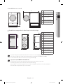
Alcove or closet installations
WARNING
• The dryer must be exhausted to the outside to reduce the risk of fire when installed in an alcove or closet.
• No other fuel-burning appliance should be installed in the same closet as the dryer.
• Place the dryer at least 18 in. (460 mm) above the floor for garage installation.
Minimum clearances between the dryer and adjacent walls or other surfaces:
Sides 1 in (25 mm) Rear 5.9 in (150 mm)
Top 17 in (432 mm) Closet front 2 in (51 mm)
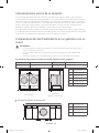
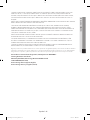
A
AA
BB
FDE
C
A 1 in. (25 mm)
B 27 in. (686 mm)
C 17 in. (432 mm)
D 2 in. (50 mm)
E 32.4 in. (823 mm)
F 5.9 in. (150 mm)
Recessed area
Side view
(closet or confined area)
Undercounter installation
A
B C D
A 39 in. (991 mm)
B 1 in. (25 mm)
C 27 in. (686 mm)
D 1 in. (25 mm)
DV5000H_DC68-03381A-15_EN.indd 10 2019-06-03 12:29:44

English - 11
02 INSTALLATION
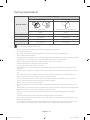
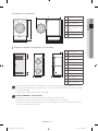
Installation with pedestal
A
B
C
EF
D
A 38.7 in. (984 mm)
B 53.3 in. (1355 mm)
C 27 in. (686 mm)
D
53 in. (1345 mm) to
clear open door
E 32.4 in. (823 mm)
F 5.9 in. (150 mm)
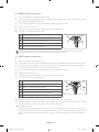
Installation with stacked washing machine and dryer
A
E
I
F
GH JKL
B
C
D
A 3 in. (76 mm)
B 48 in.² (3100 mm²)
C 24 in.² (1550 mm²)
D 3 in. (76 mm)
E 6 in. (152 mm) *
F 77.5 in. (1968 mm)
G 1 in. (25 mm)
H 27 in. (686 mm)
I 5.9 in. (150 mm)
J 1 in. (25 mm)
K 32.4 in. (823 mm)
L 8.9 in. (226 mm)
The front of the closet must have two unobstructed air openings (B, C) for a combined minimum total
area of 72 in² (465 cm²) with a minimum clearance of 3 in. (7.6 cm) at the top (A) and bottom (D).
External exhaust elbow requires additional space (L).
Stacking (MODEL NO: SKK-7A/SKK-8K)
Samsung’s Washer and Dryer can be stacked to maximize usable space.
You can purchase an optional stacking kit from your Samsung retailer.
For details about stacking and compatible models, refer to the user manual included in the stacking kit you
purchase.
DV5000H_DC68-03381A-15_EN.indd 11 2019-06-03 12:29:45

English - 12
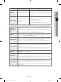
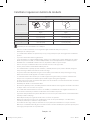
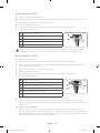
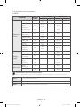
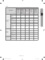
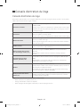
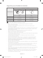
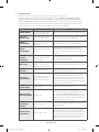
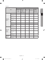
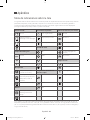
Ducting requirements
No. of 90° elbows
Weather hood type
4” (10 .16 cm) 2.5” (6.35 cm)
Recommended Use only for short-run installation
Rigid Rigid
0 24.4 m (80 ft.) 22.6 m (74 ft.)
1 20.7 m (68 ft.) 18.9 m (62 ft.)
2 17.4 m (57 ft.) 15.5 m (51 ft.)
3 14.3 m (47 ft.) 12.5 m (41 ft.)
* Do not use non-metallic flexible ducts.
• Use a 4 inch (10.2 cm) diameter rigid aluminum or rigid galvanized steel duct.
• Do not use a smaller duct.
• Ducts larger than 4 inches (10.2 cm) in diameter can result in increased accumulation of lint.
• Lint should be removed regularly.
• If a flexible metal duct must be used, use the type with a stiff sheet metal wall. Do not use a flexible duct with
a thin foil wall. A serious blockage can result if the flexible metal duct is bent too sharply.
• Never install any type of flexible duct in walls, ceilings, or other concealed spaces.
• Keep the exhaust duct as straight and short as possible.
• Secure joints with duct tape. Do not use screws.
• Plastic flexible ducts can kink, sag, be punctured, reduce airflow, extend drying times, and affect the dryer
operation.
• Exhaust systems longer than recommended can extend drying times, affect machine operations, and collect
lint.
• The exhaust duct should end with an exhaust hood with a swing-out damper to prevent back drafts and
entry of wildlife. Never use an exhaust hood with a magnetic damper.
• The hood should have at least 12 inches (30.5 cm) of clearance between the bottom of the hood and the
ground or other obstruction. The hood opening should point down.
• Never install a screen over the exhaust outlet.
• To avoid lint buildup, do not exhaust the dryer directly into a window well. Do not exhaust under a house or
porch.
• If the exhaust duct must run through an unheated area, the duct should be insulated and slope slightly down
towards the exhaust hood to reduce condensation and lint buildup.
• Inspect and clean the interior of the exhaust system at least once a year. Unplug the power cord before
cleaning.
• Check frequently to make sure the exhaust hood damper opens and closes freely.
• Check once per month, and clean at least once per year. Note: If your clothes are not getting dry, then check
the duct for obstructions.
• Do not exhaust the dryer into a wall, ceiling, crawl space, or concealed space of a building, gas vent, or any
other common duct or chimney. This could create a fire hazard from the lint expelled by the dryer.
DV5000H_DC68-03381A-15_EN.indd 12 2019-06-03 12:29:45

English - 13
02 INSTALLATION
If the new dryer is installed into an existing exhaust system you must make sure:
• The exhaust system meets all local, state, and national codes.
• That a flexible plastic duct is not used.
• To inspect and clean all lint buildup from inside the existing duct.
• The duct is not dented or crushed.
• The exhaust hood damper opens and closes freely.
• The static pressure in any exhaust system must not exceed 0.83 inches of water column, or be less than 0.
• This can be measured with the dryer running with a manometer at the point where the exhaust duct connects
to the dryer. A no-heat setting should be used. The dryer tumbler should be empty and the lint filter clean.
Exhausting
The dryer shall not be exhausted into a chimney, a wall, a ceiling, an attic, a crawl space, or a concealed space of a
building.
Exhausting the dryer to the outside will prevent large amounts of lint and moisture from being blown into the
room.
• All dryers must be exhausted to the outside.
• Do not assemble the duct with screws or other fastening means that extend into the duct and catch
lint.
• The exhaust duct should be 4 inches (102 mm) in diameter.
• The total length of flexible metal duct shall not exceed 2.4 m (7.8 ft.).
In the United States:
Use only those foil-type flexible ducts, if any, specifically identified for use with the appliance by the manufacturer
and that comply with the Outline for Clothes Dryer Transition Ducts, Subject 2158A.
In Canada:
Use only those foil-type flexible ducts, if any, specifically identified for use with the appliance by the manufacturer.
Outside the U.S. and Canada:
Refer to the local codes.
WARNING
• The dryer must be exhausted to the outside to reduce the risk of fire when installed in an alcove or
closet.
• NEVER USE A PLASTIC OR NON-METAL FLEXIBLE DUCT.
If your existing ductwork is plastic, non-metal, or combustible, replace it with metal.
Use only a metal exhaust duct that is non-flammable to ensure containment of the exhaust air, heat,
and lint.
DV5000H_DC68-03381A-15_EN.indd 13 2019-06-03 12:29:45

English - 14
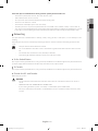
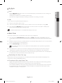
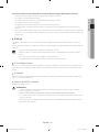
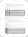
Dryer exhaust tips
WARNING: A plastic or non-metal flexible duct presents a potential fire hazard.
• Make sure your dryer is installed properly so it exhausts air easily.
• Use a 4” diameter rigid metal duct. Tape all joints, including at the dryer.
Never use lint-trapping screws.
• Keep ducts as straight as possible.
• Clean all old ducts before installing your new dryer.
• Be sure the vent flap opens and closes freely.
• Inspect and clean the exhaust system annually.
4”
Tape
Don’t let a poor exhaust system slow the drying process by:
• Restricting your dryer with a poor exhaust system.
• Using a plastic, thin foil, or non-metal flexible duct.
• Unnecessarily using long ducts that have many elbows.
• Allowing dented or clogged ducts and vent.
DV5000H_DC68-03381A-15_EN.indd 14 2019-06-03 12:29:45

English - 15
02 INSTALLATION
Gas requirements
The installation must be conformed with local codes, or in the absence of local codes, with the national
fuel gas code, ANSI Z223.1/NFPA 54, latest revision(for the UNITED STATES), or with the natural gas and
propane installation code, CSA B149.1(for Canada).
• Use only natural or LP (liquid propane) gases.
• This dryer designed for use with natural gas. If you plan to use your dryer with LP gas (liquid propane), the
conversion must be done by a qualified service technician in order to achieve safe and proper performance.
(LNG models only)
You must check the burner of your model and use the proper LP Kit accordingly. To check the detail
information of the burner, open the door and check the rating label location on the door frame.
- 20,000 BTU: LPKIT-4/XAA (DC98-04114A)
- 22,000 BTU: LPKIT-3/XAA (DC99-00792A)
• A 1/2 inch (1.27 cm) gas supply line is recommended and must be reduced to connect to the 3/8 inch (1 cm)
gas line on your dryer. The National Fuel Gas Code requires that an accessible, approved manual gas shut-off
valve be installed within 6 inches of your dryer.
• Gas dryers installed in residential garages must be raised 18 inches (46 cm) above the floor.
• Additionally, a 1/8 inch (0.3 cm) N.P.T. (National Pipe Thread) plugged tapping, accessible for test gauge
connection, must be installed immediately upstream of your dryer’s gas supply connection.
• Your dryer must be disconnected from the gas supply pipe system during any pressure testing of the system.
• Do not reuse old flexible metal gas lines. Flexible gas lines must be designed and certified by the standard for
connectors for Gas Appliances, ANSI Z21.24 • CSA 6.10.
• Any pipe joint compound used must be resistant to the action of any liquefied petroleum gas.
• As a courtesy, most local gas utilities will inspect a gas appliance installation.
• GAS IGNITION - Your dryer uses an automatic ignition system to ignite the burner. There is no constant
burning pilot.
Commonwealth of massachusetts installation instructions
Your dryer must be installed by a licensed plumber or gas fitter. A “T” handle manual gas valve must be installed in
the gas supply line to your dryer. If a flexible gas connector is used to install your dryer, the connector may not be
longer than 3 feet (36 inches).
WARNING
• Gas leaks may occur in your system, creating a dangerous situation.
• Gas leaks may not be detected by smell alone.
• Gas suppliers recommend that you purchase and install a UL-approved gas detector.
• Install and use it in accordance with the manufacturer’s instructions.
DV5000H_DC68-03381A-15_EN.indd 15 2019-06-03 12:29:46

English - 16
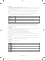
Exhaust ducting guide
Ducting
1. Make sure the dryer is installed properly so the air exhausts freely.
2. Use 4-inch rigid metal ducts. Tape all joints including the dryer connection.
Never use lint-trapping screws.
3. To facilitate the exhaust, keep the ducts as straight as possible.
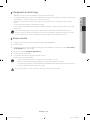
Cleaning
Clean all old ducts before installing the dryer, and make sure the vent flap opens and closes freely. We recommend
that you clean the exhaust system annually or on a regular basis.
WARNING
• To prevent fire, do not use plastic, thin-foil, or non-metal flexible ducts of any kind.
• Do not use a poor exhaust system because it slows down the dryer’s performance.
• Do not use excessively long ducts that have multiple elbows.
• Do not use crushed or clogged venting or ducts.
Electrical requirements
The wiring diagram is located on the plate below the control panel.
WARNING
• The improper connection of the equipment grounding conductor can result in a risk of electric
shock. Check with a qualified electrician or serviceman if you are in doubt as to whether your dryer is
properly grounded. Do not modify the plug provided with your dryer - if it doesn’t fit the outlet, have
a proper outlet installed by a qualified electrician.
• To prevent unnecessary risk of fire, electrical shock, or personal injury, all wiring and grounding must
be done in accordance with local codes, or in the absence of local codes, with the National Electrical
Code, ANSI/NFPA No. 70-Latest Revision (for the U.S.) or the Canadian Electrical Code CSA C22.1 -
Latest Revisions and local codes and ordinances. It is your responsibility to provide adequate electrical
services for your dryer.
• All gas installations must be done in accordance with the national Fuel Code ANSI/Z2231 - Latest
Revision (for the U.S.) or CAN/CGA - B149 Installation Codes - Latest Revision (for Canada) and local
codes and ordinances.
DV5000H_DC68-03381A-15_EN.indd 16 2019-06-03 12:29:46

English - 17
02 INSTALLATION
Electrical connections
Before operating or testing, follow all grounding instructions in the “Grounding” section on page 9.
An individual branch (or separate) circuit serving only your dryer is recommended. DO NOT USE AN EXTENSION
CORD.
Gas models – U.S. and Canada
A 120 volt, 60 Hz AC approved electrical service, with a 15-ampere fuse or circuit breaker is required.
Electric models – U.S. only
Most U.S. dryers require a 120/240 volt, 60 Hz AC approved electrical service. Some require 120/208 volt, 60 Hz
approved electrical service. The electric service requirements can be found on the data label located behind the
door. A 30-ampere fuse or circuit breaker on both sides of the line is required.
If a power cord is used, the cord should be plugged into a 30-ampere receptacle.
The power cord is NOT provided with U.S. electric model dryers.
WARNING - RISK OF ELECTRIC SHOCK
When local codes allow, the electrical supply of the dryer may be connected by means of a new power
supply cord kit, marked for use with a dryer, that is U.L. listed and rated at a minimum of120/240 volts,
30-ampere with three No. 10 copper wire conductors terminated with closed loop terminals, open-end
spade lugs with turned up ends, or with tinned leads.
• Do not reuse a power supply cord from an old dryer. The power cord electric supply wiring must be
retained at the dryer cabinet with a suitable UL-listed strain relief.
• Grounding through the neutral conductor is prohibited for (1) new branch-circuit installations, (2)
mobile homes, (3) recreational vehicles, and (4) areas where local codes prohibit grounding through
the neutral conductor. (Use a 4-prong plug for 4 wire receptacles, NEMA type 14-30R.)
Electric models – Canada Only
• A 120/240 volt, 60 Hz AC approved electrical service fused through a 30-ampere fuse or circuit breaker on
both sides of the line is required.
• All Canadian models are shipped with the power cord attached. The power cord should be plugged into a
30-ampere receptacle.
In Canada, you may not convert a dryer to 208 volts.
DV5000H_DC68-03381A-15_EN.indd 17 2019-06-03 12:29:46

English - 18
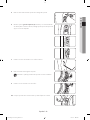
3-WIRE system connections
1. Loosen or remove the center terminal block screw.
2. Connect the neutral wire (white or center wire) of the power cord to the center, silver-colored terminal screw
of the terminal block. Tighten the screw.
3. Connect the other wires to the outer terminal block screws. Tighten the screws.
4. Tighten the strain relief screws.
5. Insert the tab of the terminal block cover into your dryer’s rear panel slot.
6. Secure the cover with a hold-down screw.
A External ground connector
B Neutral grounding wire (white or green/yellow)
C Center silver-colored terminal block screw
D Neutral wire (white or center wire)
E 3/4 in. (1.9 cm) UL-listed strain relief
If converting from a 4-wire electrical system to a 3-wire, the ground strap must be reconnected to the
terminal block support to ground the dryer frame to the neutral conductor.
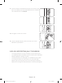
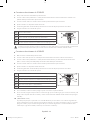
4-WIRE system connections
1. Remove the center terminal block screw.
2. Connect the ground wire (green or unwrapped) of the power cord to the external ground conductor screw.
3. Connect the neutral wire (white or center wire) of the power cord and the appliance ground wire (white or
green/yellow stripes) under the central screw of the terminal block.
4. Connect the other wires to the outer terminal block screws. Tighten the screws.
5. Tighten the strain relief screws.
6. Insert the tab of the terminal block cover into your dryer’s rear panel slot.
7. Secure the cover with a hold-down screw.
A External ground connector
B Green or bare copper wire of the power cord
C 3/4 in. (1.9 cm) UL-listed strain relief
D Center silver-colored terminal block screw
E Neutral grounding wire (white or green/yellow)
F Neutral wire (white or center wire)
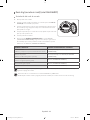
8. With a level, check your dryer and make the necessary adjustments to the leveling legs.
9. At this time, make sure all gas connections (on gas models), exhaust and electrical connections are complete.
Plug in your dryer, and check its operation by using the checklist below.
10. (GAS MODELS ONLY)
The burner may not ignite initially due to air in the gas line. Allowing your dryer to operate on a heat setting
will purge the line. If the gas does not ignite within 5 minutes, turn your dryer off and wait 5 minutes. Be sure
the gas supply to your dryer has been turned on. In order to confirm the gas ignition, check the exhaust for
heat.
DV5000H_DC68-03381A-15_EN.indd 18 2019-06-03 12:29:46

English - 19
02 INSTALLATION
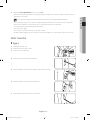
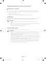
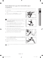
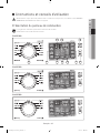
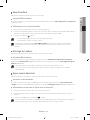
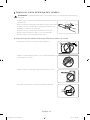
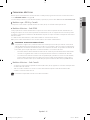
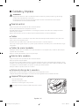
Connecting the inlet hose (Steam model only)
The dryer must be connected to the cold water faucet using the new inlet hoses. Do not use old hoses.
1. Turn the cold water faucet off.
2. Attach the brass female end of the Y connector (A) to the cold water
faucet.
3. Attach the straight end of long hose (B) to the Y connector.
4. Using pliers, tighten the coupling with an additional two-thirds turn.
A
B
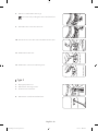
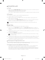
If the Y connector cannot be attached directly to the cold water
faucet, the short hose must be used.
(If space permits, please skip steps 5 to 8, and go directly to step 9.)
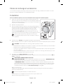
5. Attach the short inlet hose (C) to the cold water faucet.
Screw on the coupling by hand until it is seated on the faucet.
6. Using the pliers, tighten the coupling with an additional two-thirds
turn.
7. Attach the Y connector (A) to the brass male end of the small hose.
Screw on the coupling by hand until it is seated on the connector.
8. Using the pliers, tighten the coupling with an additional two-thirds
turn.
C
A
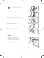
9. Attach the angled end of long hoses to the fill valve at the bottom of
the dryer rear frame. Screw on the coupling by hand until it is seated
on the fill valve connector.
10. Using pliers, tighten the coupling with an additional two-thirds turn.
11. Attach the washer hose (D) to the other side of the Y connector (A).
Screw on the hose coupling until it is tight. Using pliers, tighten the
coupling with an additional two thirds turn.
12. Check that the water faucets are on.
13. Check for leaks around the Y connector, faucets and hoses.
D
A
When you tighten the coupling with pliers, do not overtighten. This may damage the coupling.
DV5000H_DC68-03381A-15_EN.indd 19 2019-06-03 12:29:47

English - 20
Replacement parts and accessories
If your dryer requires replacement parts or accessories, contact the dealer where you purchased your dryer or the
SAMSUNG customer care center at 1-800-SAMSUNG (726-7864).
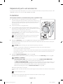
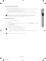
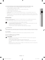
Installation
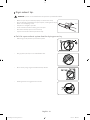
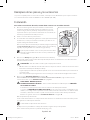
For the proper installation, we recommend that you hire a qualified installer.
1. Move your dryer to an appropriate location for the installation.
Consider installing the dryer and washer side-by-side, to allow access
to the gas, electrical, and exhaust connections. Place two of the carton
cushion-tops on the floor. Tip your dryer on its side so it lies across
both cushion-tops.
2. Set your dryer back in an upright position.
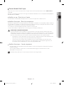
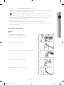
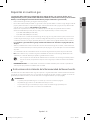
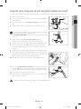
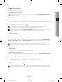
3. To ensure that the dryer provides the optimal drying performance, it
must be level. To minimize vibrations, noise, and unwanted movement,
the floor must be a perfectly level, solid surface.
To set the dryer to the same height as the washer, fully retract the
leveling feet (A) by turning them counterclockwise, then loosen the
legs by turning them clockwise.
Adjust the leveling feet only as much as necessary to level the
dryer. Extending the leveling feet more than necessary can
cause the dryer to vibrate.
A
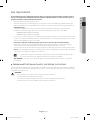
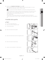
4. Review the “Exhausting” section on page 13 before installing the exhaust system.
Install the ductwork from your dryer to the exhaust hood. The crimped end of the duct sections must point
away from your dryer.
CAUTION - Before installing your dryer, remove the packing in the duct.
• DO NOT use sheet metal screws when assembling the ducting. These joints should be taped.
• Never use plastic flexible exhaust material.
• Tip for tight installations: install a section of the exhaust system onto your dryer before putting it in place.
• Use duct tape to secure this section to your dryer, but do not cover the ventilation slots at the back of
the unit in dryer cabinet.
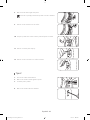
5. Review the “Electrical requirements” section on page 16.
BEFORE OPERATING OR TESTING, follow the grounding instructions in the “Grounding” section on page 9.
WARNING - U.S. MODELS
RISK OF ELECTRIC SHOCK - All U.S. models are produced for a 3-WIRE SYSTEM CONNECTION.
The dryer frame is grounded to the neutral conductor at the terminal block.
A 4-WIRE SYSTEM CONNECTION is required for new or remodeled construction, mobile homes, or if
local codes do not permit grounding through the neutral conductor. If the 4-wire system is used, the
dryer frame cannot be grounded to the neutral conductor at the terminal block.
Refer to the following instructions for “Electrical connections” on page 17.
Remove the terminal block cover plate.
Insert the power cord with a UL-listed strain relief through the hole provided in the cabinet near the terminal
block.
A strain relief must be used.
Do not loosen the nuts already installed on the terminal block. Be sure they are tight.
Use a 3/8 in. (1 cm) deep well socket.
DV5000H_DC68-03381A-15_EN.indd 20 2019-06-03 12:29:47
La page est en cours de chargement...
La page est en cours de chargement...
La page est en cours de chargement...
La page est en cours de chargement...
La page est en cours de chargement...
La page est en cours de chargement...
La page est en cours de chargement...
La page est en cours de chargement...
La page est en cours de chargement...
La page est en cours de chargement...
La page est en cours de chargement...
La page est en cours de chargement...
La page est en cours de chargement...
La page est en cours de chargement...
La page est en cours de chargement...
La page est en cours de chargement...
La page est en cours de chargement...
La page est en cours de chargement...
La page est en cours de chargement...
La page est en cours de chargement...
La page est en cours de chargement...
La page est en cours de chargement...
La page est en cours de chargement...
La page est en cours de chargement...
La page est en cours de chargement...
La page est en cours de chargement...
La page est en cours de chargement...
La page est en cours de chargement...
La page est en cours de chargement...
La page est en cours de chargement...
La page est en cours de chargement...
La page est en cours de chargement...
La page est en cours de chargement...
La page est en cours de chargement...
La page est en cours de chargement...
La page est en cours de chargement...
La page est en cours de chargement...
La page est en cours de chargement...
La page est en cours de chargement...
La page est en cours de chargement...
La page est en cours de chargement...
La page est en cours de chargement...
La page est en cours de chargement...
La page est en cours de chargement...
La page est en cours de chargement...
La page est en cours de chargement...
La page est en cours de chargement...
La page est en cours de chargement...
La page est en cours de chargement...
La page est en cours de chargement...
La page est en cours de chargement...
La page est en cours de chargement...
La page est en cours de chargement...
La page est en cours de chargement...
La page est en cours de chargement...
La page est en cours de chargement...
La page est en cours de chargement...
La page est en cours de chargement...
La page est en cours de chargement...
La page est en cours de chargement...
La page est en cours de chargement...
La page est en cours de chargement...
La page est en cours de chargement...
La page est en cours de chargement...
La page est en cours de chargement...
La page est en cours de chargement...
La page est en cours de chargement...
La page est en cours de chargement...
La page est en cours de chargement...
La page est en cours de chargement...
La page est en cours de chargement...
La page est en cours de chargement...
La page est en cours de chargement...
La page est en cours de chargement...
La page est en cours de chargement...
La page est en cours de chargement...
La page est en cours de chargement...
La page est en cours de chargement...
La page est en cours de chargement...
La page est en cours de chargement...
La page est en cours de chargement...
La page est en cours de chargement...
La page est en cours de chargement...
La page est en cours de chargement...
La page est en cours de chargement...
La page est en cours de chargement...
La page est en cours de chargement...
La page est en cours de chargement...
La page est en cours de chargement...
La page est en cours de chargement...
La page est en cours de chargement...
La page est en cours de chargement...
La page est en cours de chargement...
La page est en cours de chargement...
La page est en cours de chargement...
La page est en cours de chargement...
La page est en cours de chargement...
La page est en cours de chargement...
La page est en cours de chargement...
La page est en cours de chargement...
La page est en cours de chargement...
La page est en cours de chargement...
La page est en cours de chargement...
La page est en cours de chargement...
La page est en cours de chargement...
La page est en cours de chargement...
La page est en cours de chargement...
La page est en cours de chargement...
La page est en cours de chargement...
La page est en cours de chargement...
La page est en cours de chargement...
La page est en cours de chargement...
La page est en cours de chargement...
La page est en cours de chargement...
La page est en cours de chargement...
La page est en cours de chargement...
La page est en cours de chargement...
La page est en cours de chargement...
La page est en cours de chargement...
La page est en cours de chargement...
-
 1
1
-
 2
2
-
 3
3
-
 4
4
-
 5
5
-
 6
6
-
 7
7
-
 8
8
-
 9
9
-
 10
10
-
 11
11
-
 12
12
-
 13
13
-
 14
14
-
 15
15
-
 16
16
-
 17
17
-
 18
18
-
 19
19
-
 20
20
-
 21
21
-
 22
22
-
 23
23
-
 24
24
-
 25
25
-
 26
26
-
 27
27
-
 28
28
-
 29
29
-
 30
30
-
 31
31
-
 32
32
-
 33
33
-
 34
34
-
 35
35
-
 36
36
-
 37
37
-
 38
38
-
 39
39
-
 40
40
-
 41
41
-
 42
42
-
 43
43
-
 44
44
-
 45
45
-
 46
46
-
 47
47
-
 48
48
-
 49
49
-
 50
50
-
 51
51
-
 52
52
-
 53
53
-
 54
54
-
 55
55
-
 56
56
-
 57
57
-
 58
58
-
 59
59
-
 60
60
-
 61
61
-
 62
62
-
 63
63
-
 64
64
-
 65
65
-
 66
66
-
 67
67
-
 68
68
-
 69
69
-
 70
70
-
 71
71
-
 72
72
-
 73
73
-
 74
74
-
 75
75
-
 76
76
-
 77
77
-
 78
78
-
 79
79
-
 80
80
-
 81
81
-
 82
82
-
 83
83
-
 84
84
-
 85
85
-
 86
86
-
 87
87
-
 88
88
-
 89
89
-
 90
90
-
 91
91
-
 92
92
-
 93
93
-
 94
94
-
 95
95
-
 96
96
-
 97
97
-
 98
98
-
 99
99
-
 100
100
-
 101
101
-
 102
102
-
 103
103
-
 104
104
-
 105
105
-
 106
106
-
 107
107
-
 108
108
-
 109
109
-
 110
110
-
 111
111
-
 112
112
-
 113
113
-
 114
114
-
 115
115
-
 116
116
-
 117
117
-
 118
118
-
 119
119
-
 120
120
-
 121
121
-
 122
122
-
 123
123
-
 124
124
-
 125
125
-
 126
126
-
 127
127
-
 128
128
-
 129
129
-
 130
130
-
 131
131
-
 132
132
-
 133
133
-
 134
134
-
 135
135
-
 136
136
-
 137
137
-
 138
138
-
 139
139
-
 140
140


Samsung DV42H5200GP/A3 Manuel utilisateur
- Catégorie
- Sèche-linge
- Taper
- Manuel utilisateur
dans d''autres langues
- English: Samsung DV42H5200GP/A3 User manual
- español: Samsung DV42H5200GP/A3 Manual de usuario
Documents connexes
-
Samsung DV42H5000EW/A3 Manuel utilisateur
-
-
-
-
-
-
Samsung DV22K6800EW Manuel utilisateur
-
-