
V310056.A
Installation Guide
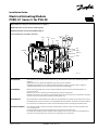
Electrical Actuating Module
PVED-CC Series 5 for PVG 20
© Danfoss, 2014-03 11072470 • Rev BB • Mar 2014 1
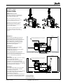
Oliestrømmens retning for standard monterede grupper.
Oil ow direction for standard assembled groups.
Richtung des Ölstroms für Standard Baugruppen.
Sens du débit pour ensembles standard.
Ved udskiftning af PVE skal både det elektriske og det hydrauliske system være afbrudt og olietryk
udlignet.
Hydraulisk olie kan påføre både miljømæssige skader og personskader.
Udskiftning af moduler kan introducere fremmedlegemer i og fejl på systemet. Det er vigtigt, at
arbejdsområdet holdes rent og at komponenterne behandles forsigtigt.
When replacing the PVE, the electrical and the hydraulic systems must be turned o and the oil
pressure released.
Hydraulic oil can cause both environmental damage and personal injuries.
Module replacement can introduce contamination and errors to the system. It is important to keep the
work area clean and components should be handled with care.
Beim auswechseln vom PVE muss das elektrische und hydraulische System ausgeschaltet sein. Es darf
kein Oeldruck im System vorhanden sein. Hydraulikoel kann zu Umwelt- und Personenschäden führen.
Es ist auf äusserste Sauberkeit zu achten und das die Komponenten vorsichtig behandelt werden.
En recharger le PVE, le système électrique et hydraulique doit être coupé et la pression d’huile doit
être contrebalancée.
L’huile hydraulique peut causée du dommage de l’environnement et blessures.
Recharger des modules peuvent introduit corps étrangers dans et sur le système. Il est d’importance
de tenir la zone du travail propre et manier les components avec précaution.
WADVARSEL
WWARNING
WWARNUNG
WAVERTISSEMENT
V310067.A
P -> A
PVT
PVBZ
PVBZ-HS
A Port
A Port
B Port
PVP-T
P -> A
PVED-CC
T0 Port

2 11072470 • Rev BB • Mar 2014 © Danfoss, 2014-03
Technical Data
Oil viscosity
Oil
viscosity
range 12 - 75 mm
2
/s [65 - 347 SUS]
min. 4 mm
2
/s [39 SUS]
max. 460 mm
2
/s [2128 SUS]
Note: Max. start up viscosity 2500 mm
2
/s
Oil temperature
Oil
temperature
range
30 → 60˚C [86 →
140˚F]
min. -30˚C [-22˚F]
max. 90˚C [194˚F]
Filtering
Filtering in the
hydraulic system
Max. allowed degree of
contamination (ISO 4406,
1999 version): 18/16/13
Oil consumption
Supply Function PVED-CC
Without
voltage
Pilot oil ow per PVED-CC neutral
0 l/min
[0 US gal/min]
With
voltage
Pilot oil ow
per PVED-CC
locked
0 l/min
[0 US gal/min]
one actuation
(neutral → max.)
0.001 l
[0.024 US gal]
continuous
actuations
0.8 l/min
[0.211 US gal/min]
Supply Voltage
Nominal (V
bat
) 11 - 32 V
Minimum (V
bat
) 9.5 V
Maximum (V
bat
) 33.5 V
Max ripple 5%
Power Consumption
Current consumption (operating@12 V) 560 mA
Power consumption (operating@12 V) 6.7 W
Current consumtion (neutral - power safe) 80 mA
Power consumtion (neutral - power safe) 1 W
Activation of solenoid valves by 9-11 V will give reduced valve performance.
>35.5 V and <9 V will shut down electronics.
Hvis den indbyggede temperatursensor på printet måler mere end 100°C [212˚F] som øjeblikkelig
temperatur eller mere end 85°C [185˚F] som gennemsnitstemperatur vil PVED-CC gå i fejltilstand.
If the build in temperature sensor on the PCB shows more than a 100°C [212˚F] as instant
temperature or more than 85°C [185˚F] as average temperatur the PVED-CC will go into a fault
state.
Falls der eingebaute Temperatursensor auf der Leiterplatte eine aktuelle Temperatur von über
100°C [212˚F] oder eine Durchschnittstemperatur von über 85°C [185˚F] misst, wird das PVED-CC
Modul in den Fehlerzustand gehen.
En cas où la sonde de temperature integrée enregistre une température instantanée supérieure à
100°C [212˚F] ou une température moyenne supérieure à 85°C [185˚F], le PVED-CC se met en
mode erreur.
PCB temperature
PCB
temperature
range
0 → 85˚C
[32 → 185˚F]
min -30˚C [-22˚F]
max avarage 85˚C [185˚F]
max instant 100˚C [212˚F]
WWarning
By operation with PCB temperature below 0°C the transition to fault mode due to spool
monitoring is delayed according to product specication.
WWarning
Ambient temperature
Operation -30° → 60°C [-22° → 140°F ]
Storage -40° → 60°C [-40° → 140°F ]

© Danfoss, 2014-03 11072470 • Rev BB • Mar 2014 3
Følgende tekniske data bygger på typiske testresultater. Der anvendes mineralsk olie med en
viskositet på 21 mm
2
/s (102 SUS) og en temperatur på 50
o
C [122
o
F].
The following technical data are from typical test results. For the hydraulic system a mineral based
hydraulic oil with a viscosity of 21 mm
2
/s [102 SUS] and a temperature of 50° C [122° F] were used.
Folgende technische Daten bauen auf typische Testergebnisse. Es wurde Erdöl mit einer Viskosität
von 21 mm
2
/s (102 SUS) und einer Temperatur von 50
o
C [122
o
F] verwendet.
Les caractéristiques techniques suivantes sont tirées de résultats de tests typiques. Pour le système
hydraulique, on a utilisé une huile minérale d’une viscosité de 21 mm
2
/s [102 SUS] et à une
température de 50° C [122° F].
Bemærk: I særligt udsatte maskiner anbefales der beskyttelse i form af afskærmning
Beachte: In besonders ausgesetzten Maschinen wird Schutz in Form von elektrischer Abschirmung empfohlen.
NB: In particulary exposed applications, protection in the form of screening is recommended.
Remarque : Pour les applications particulièrement exposées, il est recommandé d’installer une protection par écran.
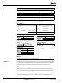
Technical Data
Typical Minimum Maximum
Power on → Full stroke 1700 ms 1600 ms 2000 ms
Neutral → Full stroke 90 ms 80 ms 120 ms
Full stroke → Neutral (Powered) 50 ms 60 ms
Full stroke → Neutral (Spring) 70 ms
PVED
~4%
V310079.A
Typical
Hysteresis at 0.02 Hz 4%*
* Measured on spool position
Response times
Hysteresis
Pilot pressure Versions
Pilot pressure
(relative to T
pressure)
nom. 13.5 bar [196 psi]
min. 12 bar [174 psi]
max. 15 bar [217 psi]
Connector Deutsch AMP JPT
Grade of enclosure IP 69 IP 66
157-520.11
La page est en cours de chargement...

© Danfoss, 2014-03 11072470 • Rev BB • Mar 2014 5
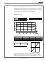
Montage af PVED
Installation of PVED
Montage von PVED
Installation de PVED
AMP/Deutsch versions:
Pakningen i PVE stikket samt pakningerne
til de enkelte ledninger, er afgørende for at
korrekt tæthed af stikket opnås.
The seal in the PVE connector and the
seals for individual conductors are crucial
for correctly sealing the connector.
Die Dichtung im PVE-Stecker sowie die
Dichtungen für die einzelnen Drähte
sind für die Dichtheit des Steckers von
entscheidendem Einuss.
Le joint de la prise PVE ainsi que les joints
de chaque conducteur, jouent un rôle
essentiel dans la qualité de l’étanchéité de
la prise.
Beskyttelse
PVE-moduler med AMP stik overholder
tæthedsgrad IP66 i henhold til IEC 529.
PVE-moduler med Deutsch stik overholder
tæthedsgrad IP69 i henhold til IEC 529.
Det anbefales dog, at PVE'en på særligt
udsatte steder beskyttes i form af en
afskærmning eller lignende.
Schutzgrad
PVE-Module mit AMP Stecker erfüllen
Schutzart IP 66 in IEC 529.
PVE-Module mit Deutsch Stecker erfüllen
Schutzart IP 69 in IEC 529.
Wenn die PVE-Module aber besonders
nassen Bedingungen ausgesetzt sind,
werden weitere Schutzmaßnahmen in Form
von einer Abschirmung empfohlen.
Protection
PVE-modules with AMP connectors conform
to enclosure IP 66 in IEC 529.
PVE-modules with Deutsch connectors
conform to enclosure IP 69 in IEC 529.
However, it is recommended to additionally
shield all such PVE-modules that are exposed
to particularly moist conditions.
Protection
Les modules PVE équipés de la prise AMP
possèdent le degré de protection IP66
conformément à la IEC 529.
Les modules PVE équipés de la prise Deutsch
possèdent le degré de protection IP69
conformément à la IEC 529.
Dans les zones particulièrement exposées, il
est cependant conseillé de protéger le PVE à
l’aide d’un écran ou d’un dispositif similaire.
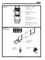
100 [4]*
215 [8.46]
70 [2.756]
V310037.A
In particularly exposed applications, protection in the form
of screening of the electrical actuator is recommended
25 Nm
[221 lbf•in]
100 [4]*
215 [8.46]
70 [2.756]
In particularly exposed applications, protection in the form
of screening of the electrical actuator is recommended
V310066.A
25 Nm
[221 lbf•in]
V310051.A
4 [0.16]
5 ±0.5 Nm
[44 ±4.4 lbf•in]
PVED
V310052.A
5 ±0.5 Nm
[44 ±4.4 lbf•in]
PVED
4 [0.16]
* Plads til demontage
* Room for dismantling
* Platz für Demontage
* Espace pour démontage

6 11072470 • Rev BB • Mar 2014 © Danfoss, 2014-03
B
A
C
D
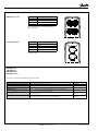
V310074.B
E
1
3
2
4
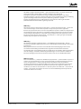
35[1.38]
25[0.98]
4200[165.35]
3800[149.61]
60[2.36]
40[1.57]]
Oil resistant PVC
P301 153
Pin 1 White Can_H
Pin 2 Blue Can_L
Pin 3 Yellow VBAT / U_DC
Pin 4 Red GND
Terminator
Code number:
110 07561
11077563 (dummy)
Deutsch-Deutsch cable
Code number :
110 07531
Kabel med stik
Cable with connector
Kabel mit Stecker
Câble avec connecteur
Deutsch version
Identikation
Identication
Identication
A: PVED-CC nummer
B: PVED-CC Serie 5 produktionscelle
C: Fremstillingsdato; år, uge, dag
D: Serienummer
E: Forsyningsspænding
A: PVED-CC number
B: PVED-CC Series 5 production cell
C: Manufacturing date; year, week, day
D: Serial number
E: Supply voltage
A: PVED-CC Nummer
B: PVED-CC Series 5 Fertigungszelle
C: Datum der Herstellung; Jahre, Woche, Tag
D: Seriennummer
E: Versorgungsspannung
A: PVED-CC numéro
B: PVED-CC series 5 production de cellules
C: Date de fabrication; année, semaine, jour
D: Numéro sériel
E: Tension d´alimentation
Deutsch connector
with four meter cable
Code number:
110 07498

© Danfoss, 2014-03 11072470 • Rev BB • Mar 2014 7
WAdvarsel
Alle mærker og typer af retningsventiler – også proportional ventiler – kan svigte og forårsage
alvorlig skade. Det er derfor vigtigt at analysere maskinen i alle enkeltheder.
Da proportionalventiler anvendes under mange forskellige driftsbetingelser og i mange
forskellige maskiner, er det alene maskinproducentens ansvar at træe det endelige produktvalg
og sikre at samtlige maskinens krav til ydelse, sikkerhed og advarsler er opfyldt.
Ved valg af reguleringssystem- og sikkerhedniveau- kan man f.eks. støtte sig til ISO 13849
(sikkerhedsrelaterede bestanddele i reguleringssystemet).
WWarning
All makes and all types of directional control valves – inclusive proportional valves – can fail and
cause serious damage. It is therefore important to analyse all aspects of the application.
Because the proportional valves are used in many dierent operation conditions and applications,
the manufacturer of the application is responsible for making the nal selection of the products-
and assuring that all performance, safety and warning requirements of the application are met.
The process of choosing the control system – and safety level – could e.g. be governed by ISO
13849 (Safety related parts of control system).
WWarning
Alle Fabrikate und Typen von Wegeventilen – einschlieβlich proportionalventile – können
versagen und schlimme Unfälle verursachen. Es ist daher wichtig, die Anwendung in allen Details
zu analysieren.
Weil proportionalventile unter vielen unterschiedlichen Arbeitsbedingungen und in vielen
verschiedenen Anwendungen benutzt werden, trägt allein der Maschinenhersteller die
verantwortung für seine endgültige wahl von produkt, und er ist ebenfalles dafür verantwortlich,
dass alle leistungs-, sicherheits- und warnungsanforderungen an seine maschine erfüllt sind.
Zur wahl vom Reglersystem und sicherheitsniveau kann man sich z.b. auf ISO 13849 stützen.
WAvertissement
Tous les distributeurs – y compris les distributeurs proportionnels – peuvent tomber en panne et
entrainer de sérieux dommages. C'est la raison pour laquelle il est important d'analyser chaque
aspect de l'application. Les vannes proportionnelles étant utilisées dans de nombreuses
conditions d'exploitation et applications diérentes, le fabricant de l'application porte l'entiére
responsabilité de la sélection nale des produits et du respect des exigences en matiére de
rendement, de sécurité et d'avertissement. Le choix du systéme de commande – et du niveau de
sécurité – peut étre fait par exemple sur la base de la norme ISO 13849 (parties du systéme de
commande relatives á la sécurite).

8 11072470 • Rev BB • Mar 2014 © Danfoss, 2014-03
-
 1
1
-
 2
2
-
 3
3
-
 4
4
-
 5
5
-
 6
6
-
 7
7
-
 8
8


dans d''autres langues
- English: Danfoss PVG 20 Installation guide
Documents connexes
-
Danfoss PVG 32 Guide d'installation
-
Danfoss PVG 20 Guide d'installation
-
-
-
-
Danfoss PVHC Mode d'emploi
-
Danfoss PVG 16 Guide d'installation
-
-
-