Falmec FPERO30U5SS Mode d'emploi
- Catégorie
- Hottes
- Taper
- Mode d'emploi
Ce manuel convient également à

Ed. 2008
Cod. 110030249 - UNDER CABINET HOOD
INSTRUCTIONS BOOKLET
LIVRET D’INSTRUCTIONS
MANUAL DE INSTRUCCIONES

Dear Sir/Madam, congratulations!
You have purchased a prestigious range hood of guaranteed quality. For best results, we
suggest that you carefully follow the operating and maintenance instructions provided
in this booklet; in addition, to order spare charcoal filters, use the special coupon on the
cover.
Chère Madame/Cher Monsieur, félicitations!
Vous venez d’acheter une hotte haut de gamme. Pour en tirer les performances les
meilleures veuillez lire avec attention le mode d’emploi et la maintenance que vous
trouvez dans ce manuel ; pour commander les filtres de rechange au carbone actif
veuillez vous servir du coupon annexé à la couverture.
Enhorabuena Señora/Señor!
Ha comprado una campana extractora de prestigio y calidad segura. Para que pueda
obtener las mejores prestaciones, le sugerimos seguir con atención las instrucciones
contenidas en este manual para el uso y el mantenimiento. Para pedir los filtros de
recambio de carbón activo, utilice el cupón adjunto a la cubierta.
Product code
ASNET30U4SS
ASROM30U4SS
ARPLU30U4SS
ASALB30U4SS
ASERO30U5SS
ASNET36U4SS
ASROM36U4SS
ARPLU36U4SS
ASALB36U4SS
ASERO36U5SS

1
29 13/16" - 35 7/8" 18 7/8"
12"
1 9/16"
6 11/16"
7 7/8"
12"
18 7/8"
3 11/16"
4 7/8
"
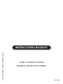
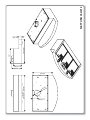
ALBA 760/912

2
29 13/16"
- 35 7/8"
5 1/8"
5 15/16"
21 1/16"
10 1/4"
2 3/8"
12"
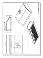
EROS 760/912

3
29 13/16"
- 35 7/8"
19 11/16"
6 11/16"
2 3/8"
7 13/16"
12"
4 7/8"
3 11/16"
15 3/4"
NETTUNO 760/912

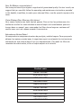
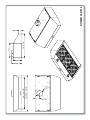
4
29 13/16"
- 35 7/8"
3 11/16"
4 7/8"
6 11/16"
7 7/8"
19 11/16"
12"
2 3/8"
PLUTONE 760/912

5
29 13/16"
- 35 7/8"
26" - 32 1/16"
19 11/16"
6 11/16"
7 13/16"
12"
2 3/8"
4 7/8"
3 11/16"
ROMBO 760/912

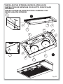
6
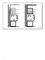
650 mm
(25,6”)
OUTSIDE DISCHARGE HOOD
Cabinet
Hood
Fig. C
650 mm
(25,6”)
RECIRCULATING HOOD
Cabinet
Recirculating kit
Hood

7
A
A
A
A
1
B
B
B
B
F
F
B
B
2
A
B
Fig. O1
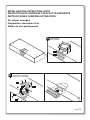
INSTALLING THE INTERNAL RECIRCULATING HOOD
INSTRUCTION DE MONTAGE POUR HOTTE À RECYCLAGE
INTÉRIEUR
INSTRUCCIONES DE MONTAJE PARA CAMPANA CON
RECIRCULACIÓN INTERIOR

8
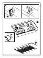
Fig. O2
INSTALLING THE EXTRACTION HOOD
INSTRUCTION DE MONTAGE POUR HOTTE ASPIRANTE
INSTRUCCIONES CAMPANA EXTRACCIÓN
Air output arranged
Préparation évacuation d’air
Salida de aire predispuesta
Standard output
Sortie standard
Salida estándar
BO02
BO01
A
Rectangular back output
Sortie arrière rectangulaire
Salida posterior rectangular
1
3
4
2
B
BO02
BO01

9
1
2
A
A
A
A
A
Rectangular upper output
Sortie supérieure rectangulaire
Salida superior rectangular
1
3
4
2
C

GB
INSTRUCTIONS BOOKLET
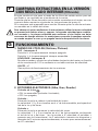
WARNINGS
A
This instruction booklet must be kept together with the appliance for future
reference. If the appliance is sold or consigned to other parties, check that
the booklet is supplied with it, to ensure that the new user has the correct
information on the operation of the range hood and is aware of the warnings.
These warnings have been provided for the your safety and the safety of oth-
ers. As a result, please read them carefully before installing and operating the
appliance.
This appliance is not intended for use by young children or infirm persons un-
less they have been adequately supervised by a responsible person to ensure
that they can use the appliance safely. Young children should be supervised to
ensure they do not play with the appliance.
The appliance must be installed by qualified personnel, in accordance with
national and local safety regulations the standards in force. If the supply cord
is damaged, it must be re-placed by the manufacturer, its service agent or
similarly qualified persons in order to avoid a hazard. Any modifications that
may be required to the electrical system for the installation of the range hood
must only be made by qualified electricians.
It is dangerous to modify or attempt to modify the characteristics of this sys-
tem. In the event of malfunctions or if repairs are required to the appliance,
do not attempt to solve the problems directly.
Repairs performed by unqualified persons may cause damage. For all repair
and other work on the appliance, contact an authorised service/spare parts
centre.
Always check that all the electrical parts (lights, exhaust device), are off when
the appliance is not being used. Read the entire instruction booklet before
performing any operations on the range hood.
The manufacturer can not be held responsible for unauthorized work. Ensure
that power to the appliance is OFF while installation or repair work is per-
formed.
Verify that the voltage, load and circuit rating information found on the data
plate (located behind the grease filter), match the household electrical supply
before installing the hood.
The range hood must only be used for the exhaust of cooking fumes in home
kitchens. The manufacturer disclaims all liability for any other use of the ap-
pliance.
The maximum weight of any object placed above the hood, or hung to it (if
possible) must not exceed 1,5 kilos. After installing the stainless steel hood,
clean it in order to remove any residue of the protective glue, and stains of
grease or oil. The manufacturer recommends its cleaning cloth available for
purchase. The manufacturer accepts no liability in case of damage caused by
the use of different detergent types.
10

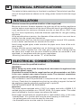
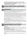
TECHNICAL SPECIFICATIONS
B
The technical data pertaining to the electric appliance The technical specifica-
tions of the appliance are shown on the rating plates located inside the range
hood.
INSTALLATION
C
(Section reserved for qualified installers of the range hood)
Minimum distance: distance between the main top of the cooking appliance
and the bottom-most section of the hood. When the hood is positioned above
a gas appliance this minimum distance must be at least 65 cm (25,6“) (see
fig. C) or more importantly, check the distances specified for the gas cooking
appliance.
In the outside exhaust version, the diameter of the entire duct run must be no
smaller than the range hood connection.
In the horizontal duct run, the duct must slope slightly (around 10%) upwards,
so as to better ventilate the air outside of the room.
Avoid using angled pipes, make sure that the pipes are at least of the mini-
mum length.
Comply with the current regulations on air discharge into the atmosphere.
If a boiler, stove, fireplace, etc. that uses gas or other fuels is being used at
the same time, make sure the room where the fumes are extracted is well
ventilated, in compliance with the current regulations.
Mounting instruction: see section “O” of the booklet.
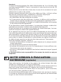
ELECTRICAL CONNECTIONS
D
(Section reserved for qualified installers)
WARNING!
Before doing any work inside the range hood, disconnect the appliance from
the mains power supply.
Check that the wires inside the range hood are not disconnected or cut; if this
is the case, contact your nearest service centre. The electrical connections
must be performed by qualified personnel.
The connections must be performed in compliance with the legal standards
in force. Check that the receptacle and wiring are able to support the load of
the appliance (see the technical specifications in point B).
THIS APPLIANCE MUST BE GROUNDED.
Important:
The hood comes equipped with a 5 ft(1.5 m) power cord with a NEMA 5-15
molded plug for connection to a 120 VAC, 60 Hz, 15 A power outlet. This outlet
must be located in the duct cover area above the hood.
Some types of appliance are supplied with a cable without plug; in this case,
“standardised” or a junction box must be used, keeping in mind that:
- the yellow/green wire must be used for the earth,
- the blue/white wire must be used for the neutral,
11

12
- the brown/black wire must be used for the phase; the cable must not come
into contact with hot parts (over 75°C).
- fit a plug that is suitable for the load to the power cable, and connect it to a
suitable power outlet.
If local codes permit, the power cord may be removed and the hood may
be connected to a hard wired electrical connection. If there is any question
concerning the electrical connection of this appliance to your power supply,
please consult a licensed electrician.
For appliances that come supplied with cable and plug please ensure they are
plugged into a circuit suitable for this appliance.
Please refer to a qualifed person. (See technical specifications in point B).
The manufacturer declines all liability if the safety standards are not ob-
served.
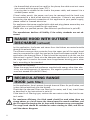
E
RANGE HOOD WITH OUTSIDE
DISCHARGE (exhaust)
In this application, the fumes and steam from the kitchen are vented outside
through an exhaust duct.
The exhaust conveyor that protrudes from the upper part of the range hood
must be connected to a duct that carries the fumes and steam outside. In this
application, the charcoal filters, if fitted, should be removed; to do this, see the
instructions in point F. There must be adequate ventilation of the room when
the range hood is used at the same time as appliances burning gas or other
fuels, according to the standard.
Deviation for Germany:
When the range hood and appliances supplied with energy other than elec-
tricity are simultaneously in operation, the negative pressure in the room
must not exceed 4 Pa (4x10 E-5 bar).
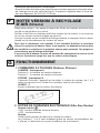
F
RECIRCULATING RANGE
HOOD (with filter)
In this application, the air passes through charcoal filters for purification, and
is then recirculated back into the kitchen.
Check that the charcoal filters are fitted to the motor, and if not, install them
as described in the instructions in point H.
If the hood is of filtering type, remove the non-return valve fitted at the mo-
tor’s outlet.
For maximum efficiency, the third speed should be used when there are
strong odours or a lot of steam, the second speed in normal conditions, and
the first speed for keeping the air clean with minimum energy consumption.
The range hood should be switched on when starting to cook, and left on
until the odours disappear.

13
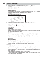
G
OPERATION
1. TWO BUTTON CONTROL PANEL (Nettuno, Plutone)
LIGHT - Switch A
Position 0: the light is off.
Position 1: the light is on.
SPEED - Switch B
This is used to start and set the speed of the motor, from 1 to 3, or with
continuous speed variator, depending on the version.
LIGHT - C
Motor operation indicator light.
2. ELECTRONIC CONTROL PANEL (Alba, Eros, Rombo)
Light pushbutton
• ON: light on (the pushbutton is lit);
• OFF: light off;
Pushbutton -
Press to reduce motor speed
Speed 1, 2 and 3 are indicated by the number of LEDs that light up (exclud-
ing the light and the timer LEDs).
Pushbutton +
Press to increase motor speed. Speed 1, 2 and 3 are indicated by the
number of LEDs that light up (excluding the light and the timer LEDs).
(In the 4-speed version the pushbutton + blinks. The fourth speed remains
on for a set duration of time. After 15 minutes the motor returns to the
third speed).
Mode pushbutton
Function: it turns hood motor on and off.
The function “desired speed” enables to start the motor at the speed that
was selected before the hood was last turned off.
Optional: version with remote control (some versions only).
WARNING:
Install the hood away from sources of electromagnetic waves, as these
could affect the correct operation of the electronic system.
Maximum operating distance: 5 metres. The maximum operating distance
could be less than 5 metres in case of electromagnetic interference by
other equipment.
Light pushbutton on remote control: light on/off.
– and + pushbutton: increase/decrease speed (to start the motor press
either the + or the – pushbutton).

14
Timer pushbutton: see instructions below.
Instructions for changing the code (only in case of malfunctions caused by
interferences):
Disconnect the hood from the power supply
Remove the cover of the remote control, change the code with the levers.
Connect the hood to the power supply and make sure the lights and the
motors are off.
Press the timer pushbutton for 2 seconds. When the red LED of the control
panel lights up press any of the buttons on the control panel.
Timer and ‘filter clogged’ alarm pushbutton
• This function allows the automatic turning off of the hood after running
for 15 minutes at the speed previously set (the pushbutton shows a flicker-
ing light).
• After about 30 hours of running the pushbutton indicates the need for
washing the metal filters (the pushbutton shows a solid red light). To dis-
able the alarm press the pushbutton for a few seconds until the red light
turns off. Then turn the hood off and on again to check that the alarm has
disappeared.
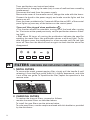
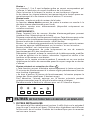
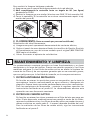
FILTERS REMOVING AND REPLACING’S INSTRUCTIONS
H
1. METAL FILTERS
To remove the metal grease-trapping filter, simply pull the handle A until
releasing it from the front guide; then tilt it slightly downwards, and slide
it out of the rear guide. To reposition the filter, repeat the operation in the
reverse order.
A
2. CHARCOAL FILTERS
To replace the charcoal filters, proceed as follows:
- remove the metal filters as described above.
To install the new fi lters see the pictures below.
To order new filters, use the coupon enclosed with this booklet or provided
by the distributor.

15
UNDER CABINET: ALBA, PLUTONE, ROMBO, NETTUNO UNDER CABINET: EROS
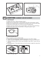
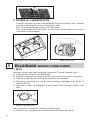
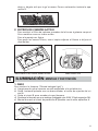
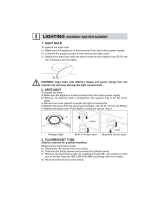
LIGHTING ASSEMBLY AND REPLACEMENT
I
1. SPOTLIGHT
To replace the lamp (“Round halogen light”):
a) Make sure the appliance is disconnected from the mains power supply.
b)
Remove, by levering with a screwdriver, the support ring A for the cover glass.
c) Remove the cover glass B to access the light compartment.
d)
Replace the lamp with the same type (halogen, max 20 W, 12 Volt, G4 fitting).
e) Replace the glass cover B and fasten it using the special ring A.
Round halogen light
How to replace a square halogen light:
a) Check that the equipment is disconnected from the power supply.
b) Open the panel completely till 90° (see figure) pressing the PUSH button
c) Replace the lamp with a similar one (halogen, max 20 W, 12 Volt, G4 con-
nection).
d) Close the panel. If the panel does not close correctly repeat the operation
at point b.
Square halogen light

16
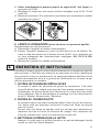
2. FLUORESCENT TUBE
(Section reserved for qualified installers)
Replacing the fluorescent tube:
a) Disconnect the device from the mains;
b) Unscrew the fixing screws and remove the bottom panel;
c) Remove the fluorescent tube, by rotating through 90°, and replace it with
one of similar features (8W-13W-21W-28W according with the model);
d) Reconnect the device to the mains.
MAINTENANCE AND CLEANING
L
Constant maintenance ensures the correct operation and efficiency of the ap-
pliance over time. Special attention should be paid to the metal grease-trap-
ping filters and the charcoal filters. Frequent cleaning of the filters and their
supports will ensure that fats and grease do not accumulate on the range
hood, with the consequent risk of fire.
1. METAL GREASE-TRAPPING FILTERS
These trap the fat and grease particles suspended in the air, and therefore
should be washed every month in hot water and detergent, without bend-
ing them. Wait until they are completely dry before repositioning them.
To remove and replace these filters, see the instructions in point H1. This
operation should be performed at regular intervals.
2. CHARCOAL FILTERS
These trap the odours present in the stream of air that passes through
them. The air is purified by passing a number of times through the filters
and being recirculated into the kitchen. The charcoal filters cannot be
cleaned, and should be replaced on average every 3-4 months (according
to use). To replace the charcoal filters, see the instructions in point H2.
3. CLEANING THE OUTSIDE OF THE APPLIANCE
The ouside of the range hhod should be cleaned using a damp cloth and
neutral liquid detergent or denatured alcohol.
In case of fingerprint-less finish (fasteel) clean only with water and neutral
soap using clean with a soft cloth, rinse and wipe dry thoroughly. Do not
use products that contain abrasive substances, rough cloths or cloths spe-
cifically designed for cleaning steel. Using abrasive substances or rough
cloths will inevitably damage the finish of steel. The steel surface will be
irrevocably damaged if the instructions above are not complied with. Keep
these instructions together with the instructions for use of your hood.
The manufacturer accepts no liability for any damage caused by non-com-
pliance with the instructions above.
4. CLEANING THE INSIDE OF THE APPLIANCE
The electrical parts or parts of the motor assembly inside the range hood
must not be cleaned using liquids or solvents.
Do not use abrasive products.
All the above operations must be performed after having disconnected the
appliance from the mains power supply.

17
SAFETY WARNINGS
M
The electrical system features an earth connection in compliance with in-
ternational safety standards; furthermore, it is compliant with the European
standard for electromagnetic compatibility.
Do not connect the appliance to flues (from boilers, fireplaces, etc.). Make
sure the mains voltage corresponds to the values on the rating plate located
inside the range hood. The minimum safety distance between the cooktop and
the range hood must be at least 65 cm (25,6”).
Never cook on “open” flames under the range hood.
Check deep-fryers during use: superheated oil may be flammable.
- Ensure there is adequate ventilation of the room when the rangehood is
used at the same time as appliances burning gas or other fuels.
- Do not flambe under the rangehood
- The exhaust air must not be discharged into a flue which is used for exhaust-
ing fumes from appliances burning gas or other fuels.
- Ensure that all regulations concerning the discharge of exhaust air have
been fulfilled before you use the appliance.
Before performing any cleaning or maintenance operations, disconnect the ap-
pliance by unplugging it or using the main switch. The manufacturer disclaims
all liability for any damage that may be directly or indirectly caused to people,
things and animals due to the failure to follow all the instructions provided in
this booklet and above all the warnings relating to the installation, operation
and maintenance of the appliance.
WARRANTY
N
The new equipment is covered by warranty.
The warranty conditions are provided by the distributor.
The manufacturer is not liable for any inaccuracies in this booklet resulting
from printing or transcription errors. The manufacturer reserves the right to
modify its products as it considers necessary or in the interests of the user,
without compromising their essential safety and operating characteristics.
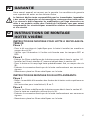
O
MOUNTING INSTRUCTIONS, RANGE
HOODS WITH BOX
INSTALLING THE INTERNAL RECIRCULATING HOOD (fig. O1)
Step 1
- Mount the air recirculation kit (specific for the hood to be installed) onto the
cabinet, using the screws provided (A).
- Check that the back output be closed by buffer BO1 and BO2.
Step 2
- Remove the hood’s metal filters as described in section H1.
- Install the carbon filters (F) as described in section H2.
- Mount the hood onto the recirculation kit that was previously installed, using

18
the screws provided (B).
- Connect the hood’s electric system, in compliance with current norms.
- Put the metal filters back in place.
INSTALLING THE EXTRACTION HOOD (fig. O2)
Step 1
- Decide how the fumes are to be expelled (from the top or from the back).
- See instructions for the configuration A, B or C.
Step 2
- Remove the hood’s metal filters as described in section H1.
- Mount the hood onto the cabinet with the screws provided (A).
- Connect the hood’s electric system, in compliance with current norms.
- Put the metal filters back in place.
La page est en cours de chargement...
La page est en cours de chargement...
La page est en cours de chargement...
La page est en cours de chargement...
La page est en cours de chargement...
La page est en cours de chargement...
La page est en cours de chargement...
La page est en cours de chargement...
La page est en cours de chargement...
La page est en cours de chargement...
La page est en cours de chargement...
La page est en cours de chargement...
La page est en cours de chargement...
La page est en cours de chargement...
La page est en cours de chargement...
La page est en cours de chargement...
La page est en cours de chargement...
La page est en cours de chargement...
La page est en cours de chargement...
La page est en cours de chargement...
-
 1
1
-
 2
2
-
 3
3
-
 4
4
-
 5
5
-
 6
6
-
 7
7
-
 8
8
-
 9
9
-
 10
10
-
 11
11
-
 12
12
-
 13
13
-
 14
14
-
 15
15
-
 16
16
-
 17
17
-
 18
18
-
 19
19
-
 20
20
-
 21
21
-
 22
22
-
 23
23
-
 24
24
-
 25
25
-
 26
26
-
 27
27
-
 28
28
-
 29
29
-
 30
30
-
 31
31
-
 32
32
-
 33
33
-
 34
34
-
 35
35
-
 36
36
-
 37
37
-
 38
38
-
 39
39
-
 40
40


Falmec FPERO30U5SS Mode d'emploi
- Catégorie
- Hottes
- Taper
- Mode d'emploi
- Ce manuel convient également à
dans d''autres langues
Documents connexes
-
Falmec FIMAS46B9SS2 Mode d'emploi
-
Falmec FISAB28B3SS Mode d'emploi
-
Falmec FIMAR28B6SS Mode d'emploi
-
Falmec FIVAL34B5SS1 Mode d'emploi
-
-
Falmec DANILO-PROLITE INSERT 28” 2M Mode d'emploi
-
Falmec FLIPPER 1420 Le manuel du propriétaire
-
Futuro Futuro WL27MURMOTIONLED Le manuel du propriétaire
Autres documents
-
Bertazzoni KIN30PROX Manuel utilisateur
-
-
Bosch PXX875D67E Manuel utilisateur
-
BALAY 3EBC989LU/35 Guide d'installation
-
-
-
 Futuro Futuro WL36BOSTON Lighting
