Faber Tratto Isola 36 SSV with VAM Guide d'installation
- Catégorie
- Hottes
- Taper
- Guide d'installation

TRATIS36SSV
TRATTO IS 36"
Installation Instructions
Use and Care Information
Instructions d'installation
Utilisez et d'entretien
Instrucciones de instalación
Información de uso y cuidado

2
READ AND SAVE THESE INSTRUCTIONS BEFORE YOU START
INSTALLING THIS RANGEHOOD
WARNING: - TO REDUCE THE RISK OF A RANGE TOP GREASE FIRE:
a) Never leave surface units unattended at high settings. Boilovers cause smoking and
greasy spillovers that may ignite. Heat oils slowly on low or medium setting.
b)AlwaysturnhoodONwhencookingathighheatorwhenambeingfood(i.e.Crepes
Suzette, Cherries Jubilee, Peppercorn Beef Flambé).
c) Clean ventilating fans frequently. Grease should not be allowed to accumulate on fan
orlter.
d) Use proper pan size. Always use cookware appropriate for the size of the surface element.
WARNING: - TO REDUCE THE RISK OF INJURY TO PERSONS IN THE EVENT OF A
RANGE TOP GREASE FIRE, OBSERVE THE FOLLOWING*:
a)SMOTHERFLAMESwithaclose-ttinglid,cookiesheet,ormetaltray,thenturnofftheburner.
BECAREFULTOPREVENTBURNS.IftheamesdonotgooutimmediatelyEVACUATE
AND CALL THE FIRE DEPARTMENT.
b) NEVER PICK UP A FLAMING PAN - You may be burned.
c) DO NOT USE WATER, including wet dishcloths or towels - a violent steam explosion will
result.
d) Use an extinguisher ONLY if:
1. You know you have a Class ABC extinguisher, and you already know how to operate it.
2. Thereissmallandcontainedintheareawhereitstarted.
3. Theredepartmentisbeingcalled.
4. Youcanghttherewithyourbacktoanexit.
* Based on "Kitchen Firesafety Tips" published by NFPA
WARNING - TO REDUCE THE RISK OF FIRE OR ELECTRIC SHOCK, do not use this
fan with any solid-state speed control device.
WARNING - TO REDUCE THE RISK OF FIRE, ELECTRICAL SHOCK, OR INJURY TO
PERSONS, OBSERVE THE FOLLOWING:
1. Use this unit only in the manner intended by the manufacturer. If you have any
questions, contact the manufacturer.
2. Before servicing or cleaning unit, switch power off at service panel and lock the
service disconnecting means to prevent power from being switched on acciden-
tally. When the service disconnecting means cannot be locked, securely fasten a
prominent warning device, such as a tag, to the service panel.
CAUTION: For General Ventilating Use Only. Do Not Use To Exhaust Hazardous or
Explosive Materials and Vapors.
WARNING - TO REDUCE THE RISK OF FIRE, ELECTRICAL SHOCK, OR INJURY TO
PERSONS, OBSERVE THE FOLLOWING:
1. InstallationWorkAndElectricalWiringMustBeDoneByQualiedPerson(s)InAccor-
dance With All Applicable Codes And Standards, Including Fire-Rated Construction.
2. Sufcientairisneededforpropercombustionandexhaustingofgasesthrough
theue(chimney)offuelburningequipmenttopreventbackdrafting.Followthe
heating equipment manufacturer's guideline and safety standards such as those
publishedbytheNationalFireProtectionAssociation(NFPA),andtheAmerican
SocietyforHeating,RefrigerationandAirConditioningEngineers(ASHRAE),and
the local code authorities.

3
3. When cutting or drilling into wall or ceiling, do not damage electrical wiring and
other hidden utilities.
4. Ducted fans must always be vented to the outdoors.
ALL WALL AND FLOOR OPENINGS WHERE THE RANGEHOOD IS INSTALLED MUST
BE SEALED.
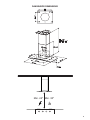
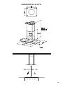
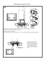
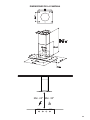
This rangehood requires at least 24" of clearance between the bottom of the rangehood
and the cooking surface or countertop. This hood has been approved by UL at this distance
from the cooktop.
This minimum clearance may be higher depending on local building codes. For gas cooktops
and combination ranges, a minimum of 30" is recommended and may be required.
Overhead cabinets on both sides of this unit must be a minimum of 18" above the cooking surface
or countertop. Consult the cooktop or range installation instructions given by the manufacturer
before making any cutouts.
MOBILE HOME INSTALLATION The installation of this rangehood must conform to the
Manufactured Home Construction and Safety Standards, Title 24 CFR, Part 3280 (formerly
Federal Standard for Mobile Home Construction and Safety, Title 24, HUD, Part 280). See
Electrical Requirements.
• Venting system MUST terminate outside the home.
• DO NOT terminate the ductwork in an attic or other enclosed space.
• DO NOT use 4" laundry-type wall caps.
• Flexible-type ductwork is not recommended.
• DO NOT obstruct the ow of combustion and ventilation air.
• Failure to follow venting requirements may result in a re.
WARNING
!
VENTING REQUIREMENTS
Determine which venting method is best for your application. Ductwork can extend either through the
wall or the roof.
The length of the ductwork and the number of elbows should be kept to a minimum to provide efcient
performance. The size of the ductwork should be uniform. Do not install two elbows together. Use
duct tape to seal all joints in the ductwork system. Use caulking to seal exterior wall or oor opening
around the cap.
Flexible ductwork is not recommended. Flexible ductwork creates back pressure and air turbulence
that greatly reduces performance.
Make sure there is proper clearance within the wall or oor for exhaust duct before making cutouts.
Do not cut a joist or stud unless absolutely necessary. If a joist or stud must be cut, then a supporting
frame must be constructed.
WARNING - To Reduce The Risk Of Fire, Use Only Metal Ductwork.
CAUTION-Toreduceriskofreandtoproperlyexhaustair,besuretoductairoutside–Do
not vent exhaust air into spaces within walls or ceilings or into attics, crawl spaces, or garages.

4
ELECTRICAL REQUIREMENTS
A 120 volt, 60 Hz AC-only electrical supply is required on a separate 15 amp fused circuit. A time-delay
fuse or circuit breaker is recommended. The fuse must be sized per local codes in accordance with
the electrical rating of this unit as specied on the serial/rating plate located inside the unit near the eld
wiring compartment.
ELECTRICAL INSTALLATION WITH WIRING BOX
THIS UNIT MUST BE CONNECTED WITH COPPER WIRE ONLY. Wire sizes must conform to the
requirements of the National Electrical Code, ANSI/NFPA 70 - latest edition, and all local codes and
ordinances. Wire size and connections must conform with the rating of the appliance. Copies of the
standard listed above may be obtained from:
National Fire Protection Association
Batterymarch Park
Quincy, Massachusetts 02269
This appliance should be connected directly to the fused disconnect (or circuit breaker) through
exible, armored or nonmetallic sheathed copper cable. Allow some slack in the cable so the
appliance can be moved if servicing is ever necessary. A UL Listed, 1/2" conduit connector must
be provided at each end of the power supply cable (at the appliance and at the junction box).
When making the electrical connection, cut a 1 1/4" hole in the wall. A hole cut through wood
must be sanded until smooth. A hole through metal must have a grommet.
• Electrical ground is required on this rangehood.
• If cold water pipe is interrupted by plastic, nonmetallic gaskets or other materials, DO
NOT use for grounding.
• DO NOT ground to a gas pipe.
• DO NOT have a fuse in the neutral or grounding circuit. A fuse in the neutral or
grounding circuit could result in electrical shock.
• Check with a qualied electrician if you are in doubt as to whether the rangehood is
properly grounded.
• Failure to follow electrical requirements may result in a re.
WARNING
!
StateofCaliforniaProposition65Warning(USonly)
WARNING
This product contains chemicals known to the State of California to cause cancer and birth
defects or other reproductive harm.
For more information go to www.P65Warnings.ca.gov

5
RANGEHOOD DIMENSIONS
Min. 24" Min. 30"

6
10
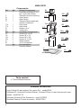
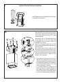
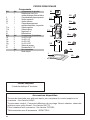
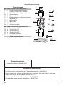
MAIN PARTS
Components
Ref. Qty. Product Components
1 1 Hood Body, complete with: Con-
trols, Light, Filters, Blower.
2 1 Telescopic Chimney comprising:
2.1 1 Upper Section
2.2 1 Lower Section
7.1 1 Telescopic frame complete with
extractor, consisting of:
7.1a 1 Upper frame
7.1b 1 Lower frame
10 1 Damper ø 5 7/8"
24 1 Junction Box
Ref. Qty. Installation Components
12f 2 Screws 3/16" x 9/16"
12c 2 Screws 1/8" x 1/4"
12e 4 Screws 1/8" x 3/8"
12q 4 Screws 1/4" x 9/16"
21 1 Drilling template
22 4 1/4" int. dia washers
Qty. Documentation
1 Instruction Manual
1
2.2
2.1
21
7.1
12q
22
12c
12e
12f
24
7.1a
7.1b
Available Accessories
-HighCeilingKitthatreplacestheupperue.-sku#HIGH2.
- Ductless Kit - Includes Ductless Diverter, Charcoal Filters, Lower chimney with vent
grates-sku#DUCT2
-ActivatedCharcoalFilterAccessory-sku#FILTER2
- Wireless RemoteControlAccessory-REMCTRL2
Parts needed
-6"RoundMetalductwork

7
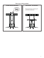
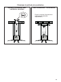
Choose your ducting method
Non Ducted - RecirculationDucted Venting Installation
RequiresDuctlessAccessoryKit
(purchased separately)
6 "

8
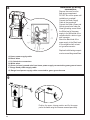
1
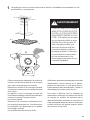
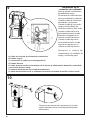
Putathick,protectivecoveringovercooktop,
set-in range or countertop to protect from
damage or dirt.
Determineandclearlymarkwithapencilonthe
ceiling where the rangehood will be installed.
A template 21 for mounting the support is
supplied in the carton with the support. Use
thistemplatetomarkholesfor
support on the ceiling.
Determineand make necessary cutsforthe
ductwork.Theductopeningisshownonthe
mounting template. Install
ductworkbeforemountingthehood.
Determine the proper location for the Power
Supply Cable as indicated on the template.
Use a 1 1/4" Drill Bit to make this hole. Run
thePowerSupplyCable.Usecaulkingtoseal
around the hole.
A knockout for threading through the Power
Supply from the ceiling is located on the top
of the frame. Do not connect the Power Cable
to the Wiring Box or power up the hood at this
time.Runenoughpowercablefromtheceiling
to reach the wiring box on the hood.
Ø 10 mm
x4
21
1 1/4"
Donotmakeanycutoutsuntilyouhavedecidedwhetherthisinstallationwillbeductedor
non-duct and then plan accordingly.
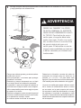
DUE TO THE SIZE AND
WEIGHT OF THIS RANGE-
HOOD, THE SUPPORT MUST
BE FIRMLY ATTACHED TO
THE CEILING. For plaster or
sheet rock ceiling, the support
must be attached to the joists.
If this is not possible, a support
structure must be built behind
the plaster or sheet rock. The
manufacturer assumes no re-
sponsibility forinjury or damage
caused by improper installa-
tions.
WARNING
!

9
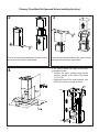
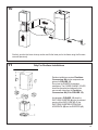
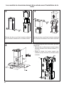
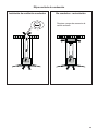
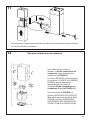
Chimney Flues Must Be Removed Before Installing the Hood
2
3
4
Loosen the two screws fastening the lower chimney
and remove this from the lower frame.
If you need to adjust the height of the frame,
proceed as follows:
• Unfasten the metric screws joining the two
columns, located at the sides of the frame
(1,2,3,4,5,6).
• Adjust the frame to the height required, then
ret all the screws removed as above.
Loosen the two screws fastening the upper chimney
and remove this from the upper frame.
1
4
MIN
740
mm
MAX
940
mm
2
3
5
6

10
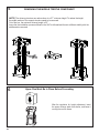
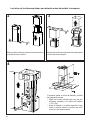
14. REMOVING THE MIDDLE TRESTLE COMPONENT
NOTE: The chimney structure can reduce down to a 27 " minimum height. To reduce the height,
the middle section of the support structure needs to be removed.
Out of the box, the minimum chimney length is 32 ".
Insure the the installation process outlined in the U&C is followed and there is sufficient stability with the
middle section removed.
5
NOTE: The chimney structure can reduce down to a 27 " minimum height. To reduce the height,
the middle section of the support structure needs to be removed.
Out of the box, the minimum chimney length is 32 ".
Insure the the installation process outlined in the U&C is followed and there is sufcient stability with the
middle section removed.
REMOVING THE MIDDLE TRESTLE COMPONENT
6
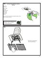
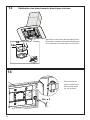
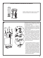
After the regulation for height adjustment, insert
the upper chimney stack from above, and leave it
running free on the frame.
Upper Flue Must Be In Place Before Proceeding

11
7
Install Damper that is included with the Hood before
connecting to the ductwork.
Only for Ducted Venting Installation
8
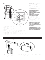
Now take either your wood screws or bolts
depending on your set-up and screw all four
into the pilot holes and leave 1/4" of the
heads exposed.
Next install a UL or CSA listed strain relief
in the wiring box so that the screws can
be tightened after the chimney support is
attached to the ceiling.
Now lift the chimney support into it's nal
position and feed the electrical supply through
the strain relief.
Next position the chimney support so that
the large end of the keyhole slots are over
the ceiling attachment screws or bolts. Then
push the chimney support so that the bolts
are in the neck of the slots. Tighten all four
screws or bolts securely.
• The frame mountings must be secure to
withstand the weight of the hood and any
stresses caused by the occasional side
thrust applied to the device. On completion,
check that the base is stable, even if the
frame is subjected to bending.
• In all cases where the ceiling is not
strong enough at the suspension point,
the installer must provide strengthening
using suitable plates and backing pieces
anchored to the structurally sound parts.

12
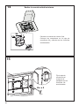
Installation of wiring
connection
Remove the cover from the
eld wiring compartment.
DO NOT turn on the power until
installation is complete!
Connect the Power Supply
Cable to the rangehood.
Connect the Green (Green and
Yellow) ground wire under the
Green grounding screw. Attach
the White lead of the power
supply to the White lead of the
rangehood with a twist-on type
wire connector.
Attach the Black lead of the
power supply to the Black lead
of the rangehood with a twist-
on type wire connector.
Replace the eld wiring compart-
ment cover and the grease lters.
A. Home power supply cable
B. Black wires
C. UL listed wire connectors
D. White wires
E. Green (or bare) ground wire from home power supply connected to green ground screw
F. Range hood power supply cable
G. Range hood power supply cable connected to green ground screw
Version 02/12 - Page 8
FIGURE 13
MAKE THE ELECTRICAL CONNECTION
Remove the cover from the eld wiring compartment. (SEE
FIGURE 11) DO NOT turn on the power until installation is
complete! Connect the Power Supply Cable to the rangehood.
Connect the Green (Green and Yellow) ground wire under the
Green grounding screw. Attach the White lead of the power
supply to the White lead of the rangehood with a twist-on type
wire connector. Attach the Black lead of the power supply
to the Black lead of the rangehood with a twist-on type wire
connector.
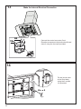
1. The UPPER CHIMNEY
COVER (C in FIGURE 13)
attaches to the top of the
support structure using two
screws provided (G in FIGURE
13). If using the High Ceiling
Chimney Kit, use the UPPER
CHIMNEY COVER supplied
with the kit. Slide up and
attach the UPPER CHIMNEY
COVER.
2. Attach the duct work to the
DAMPER (M in FIGURE 1).
Make sure to seal all joints with
duct tape to prevent leaks.
3. The LOWER CHIMNEY
COVER (B in FIGURE 13)
attaches using two screws
provided (G in FIGURE 13).
Install the LOWER CHIMNEY
COVER by sliding it up over
the support and the UPPER
CHIMNEY COVER.
For ductless installations, line up the DUCTLESS DIVERTER
EXTENSIONS HORIZONTAL (B in FIGURE 12) with the holes
in the LOWER CHIMNEY COVER (D in FIGURE 12) and snap
in the VENT GRIDS (C in FIGURE 12).
INSTALLING THE RANGEHOOD
A. Home power supply cable
B. Black wires
C. UL listed wire connectors
D.White wires
E. Green (or bare) ground wire from home power supply
connected to green ground screw
F. Range hood power supply cable
G.Range hood power supply cable connected to green
ground screw
FIGURE 11
Ductless installations require
a Ductless Conversion
Kit whose components are
pictured in FIGURE 12. Do
not use the DAMPER (M
in FIGURE 1) for ductless
installations. The LOWER
CHIMNEY COVER (B
in FIGURE 1) should be
discarded and replaced by
the new one with holes from
the Ductless Conversion Kit
(D in FIGURE 12).
As indicated in FIGURE
12, place the DUCTLESS
DIVERTER (A) over the
exhaust opening of the EASY
CUBE (E). Fit the DUCTLESS
DIVERTER EXTENSIONS
HORIZONTAL (B) into the
DIVERTER (A).
FIGURE 12
FOR DUCTLESS INSTALLATIONS
9
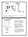
Position the upper chimney section and x the upper
part to the frame using the 2 screws removed previously.
8

13
11
Similarly, position the lower chimney section and x the lower part to the frame using the 2 screws
removed previously.
10
Only For Ductless Installations
Ductless installations require a Ductless
Conversion Kit whose components are
pictured in FIGURE 12.
Do not use the DAMPER for ductless
installations. The LOWER CHIMNEY COVER
should be discarded and replaced by the
new one with holes from the Ductless
Conversion Kit (D in FIGURE 12).
As indicated in FIGURE 12, place the
DUCTLESS DIVERTER (A) over the exhaust
opening of the EASY CUBE (E). Fit the
DUCTLESS DIVERTER EXTENSIONS
HORIZONTAL (B) into the DIVERTER (A).
Version 02/12 - Page 8
FIGURE 13
MAKE THE ELECTRICAL CONNECTION
Remove the cover from the eld wiring compartment. (SEE
FIGURE 11) DO NOT turn on the power until installation is
complete! Connect the Power Supply Cable to the rangehood.
Connect the Green (Green and Yellow) ground wire under the
Green grounding screw. Attach the White lead of the power
supply to the White lead of the rangehood with a twist-on type
wire connector. Attach the Black lead of the power supply
to the Black lead of the rangehood with a twist-on type wire
connector.
1. The UPPER CHIMNEY
COVER (C in FIGURE 13)
attaches to the top of the
support structure using two
screws provided (G in FIGURE
13). If using the High Ceiling
Chimney Kit, use the UPPER
CHIMNEY COVER supplied
with the kit. Slide up and
attach the UPPER CHIMNEY
COVER.
2. Attach the duct work to the
DAMPER (M in FIGURE 1).
Make sure to seal all joints with
duct tape to prevent leaks.
3. The LOWER CHIMNEY
COVER (B in FIGURE 13)
attaches using two screws
provided (G in FIGURE 13).
Install the LOWER CHIMNEY
COVER by sliding it up over
the support and the UPPER
CHIMNEY COVER.
For ductless installations, line up the DUCTLESS DIVERTER
EXTENSIONS HORIZONTAL (B in FIGURE 12) with the holes
in the LOWER CHIMNEY COVER (D in FIGURE 12) and snap
in the VENT GRIDS (C in FIGURE 12).
INSTALLING THE RANGEHOOD
A. Home power supply cable
B. Black wires
C. UL listed wire connectors
D.White wires
E. Green (or bare) ground wire from home power supply
connected to green ground screw
F. Range hood power supply cable
G.Range hood power supply cable connected to green
ground screw
FIGURE 11
Ductless installations require
a Ductless Conversion
Kit whose components are
pictured in FIGURE 12. Do
not use the DAMPER (M
in FIGURE 1) for ductless
installations. The LOWER
CHIMNEY COVER ( B
in FIGURE 1) should be
discarded and replaced by
the new one with holes from
the Ductless Conversion Kit
(D in FIGURE 12).
As indicated in FIGURE
12, place the DUCTLESS
DIVERTER (A) over the
exhaust opening of the EASY
CUBE (E). Fit the DUCTLESS
DIVERTER EXTENSIONS
HORIZONTAL (B) into the
DIVERTER (A).
FIGURE 12
FOR DUCTLESS INSTALLATIONS

14
12
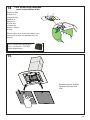
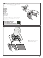
Screw the 2 screws 12f half way into the holes provided in the sides of the bottom of the frame.
Remove the grease lters from the hood canopy.
Remove any activated charcoal lters.
Lift the hood canopy and engage the screws 12f in the slots as far as they will go.
Working from below, x the
hood canopy to the frame
where indicated, using the 4
screws 12q and 4 washers 22
provided, then tighten all the
screws securely.
I
I
T[
[
Attachment of Hood Canopy

15
13
Connect the control connector Cmd.
Place the connectors in the junction box 24 and
close it using the 4 screws provided.
14
12c x 2
Fix the junction box
to the hood body
using the 2 screws
12c provided.
H
Make the Internal Electrical Connection

16
14
For Non-Ducted Recirculation
Option
RequiredActivatedCharcoalFilter
Accessory-sku#-FILTER2
(purchased separately)
Attach a
charcoal
lterinthe
correct
position and
blockitby
thexing
hooksas
shown.
Unlockthexinghooks(towardsthebackofthe
insert hood) to remove.
Reinstall the grease lters
from the hood canopy.
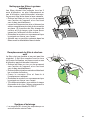
15

17
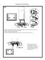
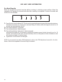
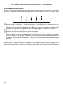
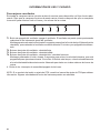
USE AND CARE INFORMATION
T1 T2 T3 T4 L
LT1 T2 T3 T4
For Best Results
Startthe rangehood severalminutes before cookingto developproperairow.Allowthe
rangehoodtooperateforseveralminutesaftercookingiscompletetoclearallsmokeand
odorsfromthekitchen.
T1.Fanoffbutton:turntheblowerOff.Thefancanbeoperatedbypressinganyofthefansettingbuttons.
Holddownthisbuttonfor2secondstoactivateDelayofffunctionwhichwillkeepthefanonfor15
minutes and automatically shut off.
T2. Fan settings buttons: Low speed.
T3. Fan settings buttons: Medium speed.
T4. Fan settings buttons: High speed / Intensive speed.
Hold down the button for 2 seconds to activate the intensive speed, which is timed to run for 10
minutes. At the end of this time it will automatically return to the speed set before.Suitable to deal
withmaximumlevelsofcookingfumes.
L. Light button: On/Off switch for the lights.
NOTE:IfyourproducthashadaCFMadjustment,refertotheCFMadjustmentmanualfortheinfor-
mation. Some motor speeds or functions may be reduced.

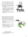
18
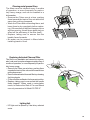
Cleaningmetalgreaselters
Theltersmustbecleanedevery2months
ofoperation,ormorefrequentlyforparticu-
larly heavy usage, and can be washed in a
dishwasher.
• RemovetheFiltersoneatatime,pushing
themtowardsthebackoftheunitandatthe
same time pulling downward.
• Wash the Filters without bending them, and
leave them to dry completely before replac-
ing.(Ifthesurfaceofthelterchangescolour
as time goes by, this will have absolutely no
effectontheefciencyofthelteritself.)
• Replace, taking care to ensure that the
handle faces forwards.
• No water canbe present in ltersbefore
installingbackinhood.
Replacing Activated Charcoal Filter
Thelterisnotwashableandcannotberegener-
ated, and must be replaced approximately every 4
monthsofoperation,ormorefrequentlyforparticu-
larly heavy usage.
• RemovetheFiltersoneatatime,pushingthem
towardsthebackoftheunitandatthesametime
pulling downward.
• Removethesaturatedcharcoallterbyreleasing
thexinghooks.
• Fitthenewlterandfastenitinitscorrectposition.
• Replace,takingcaretoensurethatthehandle
faces forwards. "When used in recirculation
mode,toReducetheRiskofFireandShock
useonlyconversionkitModelFILTER2".
Lighting Unit
• LED lights must be replaced by Faber factory authorized
service.

19
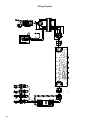
Wiring Diagram
991.0439.886 H90-305
D002531_01
991.0439.886 H90-305
D002531_01

20
January 4, 2016
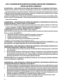
FABER CONSUMER WARRANTY & SERVICE
All Faber products are warranted against any defect in materials or workmanship for the original purchaser
for a period of 1 year from the date of original purchase (requires proof of purchase). This warranty covers
labor and replacement parts. Faber, at its option, may repair or replace the product or components
necessary to restore the product to good working condition. To obtain warranty service, contact the dealer
from whom you purchased the range hood, or the local Faber distributor. If you cannot identify a local Faber
distributor, contact us at (508) 358-5353 for the name of a distributor in your area.
The following is not covered by Faber's warranty:
1. Service calls to correct the installation of your range hood, to instruct you how to use your range hood, to
replace or repair house fuses or to correct house wiring or plumbing.
2. Service calls to repair or replace range hood light bulbs, fuses or filters. Those consumable parts are
excluded from warranty coverage.
3. Repairs when your range hood is used for other than normal, single-family household use.
4. Damage resulting from accident, alteration, misuse, abuse, fire, flood, acts of God, improper installation,
installation not in accordance with electrical or plumbing codes or Faber documentation, or use of products
not approved by Faber.
5. Replacement parts or repair labor costs for units operated outside the United States or Canada, including
any non-UL or C-UL approved Faber range hoods.
6. Repairs to the hood resulting from unauthorized modifications made to the range hood.
7. Expenses for travel and transportation for product service in remote locations and pickup and delivery
charges. Faber range hoods should be serviced in the home.
THIS WARRANTY DOES NOT ALLOW RECOVERY OF INCIDENTAL OR CONSEQUENTIAL DAMAGES, INCLUDING, WITHOUT
LIMITATION, DIRECT, INDIRECT, INCIDENTAL, SPECIAL OR CONSEQUENTIAL DAMAGES, PERSONAL INJURY/WRONGFUL
DEATH OR LOST PROFITS FABER WARRANTY IS LIMITED TO THE ABOVE CONDITIONS AND TO THE WARRANTY PERIOD
SPECIFIED HEREIN AND IS EXCLUSIVE. EXCEPT AS EXPRESSLY SPECIFIED IN THIS AGREEMENT, FABER DISCLAIMS ALL
EXPRESS OR IMPLIED CONDITIONS, REPRESENTATIONS, AND WARRANTIES INCLUDING, WITHOUT LIMITATION, ANY
IMPLIED WARRANTIES OF MERCHANTABILITY OR FITNESS FOR A PARTICULAR PURPOSE
.
This warranty gives you specific legal rights that may vary from state to state.
Model#: ______________________________ Serial #: _____________________________
La page est en cours de chargement...
La page est en cours de chargement...
La page est en cours de chargement...
La page est en cours de chargement...
La page est en cours de chargement...
La page est en cours de chargement...
La page est en cours de chargement...
La page est en cours de chargement...
La page est en cours de chargement...
La page est en cours de chargement...
La page est en cours de chargement...
La page est en cours de chargement...
La page est en cours de chargement...
La page est en cours de chargement...
La page est en cours de chargement...
La page est en cours de chargement...
La page est en cours de chargement...
La page est en cours de chargement...
La page est en cours de chargement...
La page est en cours de chargement...
La page est en cours de chargement...
La page est en cours de chargement...
La page est en cours de chargement...
La page est en cours de chargement...
La page est en cours de chargement...
La page est en cours de chargement...
La page est en cours de chargement...
La page est en cours de chargement...
La page est en cours de chargement...
La page est en cours de chargement...
La page est en cours de chargement...
La page est en cours de chargement...
La page est en cours de chargement...
La page est en cours de chargement...
La page est en cours de chargement...
La page est en cours de chargement...
La page est en cours de chargement...
La page est en cours de chargement...
La page est en cours de chargement...
La page est en cours de chargement...
-
 1
1
-
 2
2
-
 3
3
-
 4
4
-
 5
5
-
 6
6
-
 7
7
-
 8
8
-
 9
9
-
 10
10
-
 11
11
-
 12
12
-
 13
13
-
 14
14
-
 15
15
-
 16
16
-
 17
17
-
 18
18
-
 19
19
-
 20
20
-
 21
21
-
 22
22
-
 23
23
-
 24
24
-
 25
25
-
 26
26
-
 27
27
-
 28
28
-
 29
29
-
 30
30
-
 31
31
-
 32
32
-
 33
33
-
 34
34
-
 35
35
-
 36
36
-
 37
37
-
 38
38
-
 39
39
-
 40
40
-
 41
41
-
 42
42
-
 43
43
-
 44
44
-
 45
45
-
 46
46
-
 47
47
-
 48
48
-
 49
49
-
 50
50
-
 51
51
-
 52
52
-
 53
53
-
 54
54
-
 55
55
-
 56
56
-
 57
57
-
 58
58
-
 59
59
-
 60
60


Faber Tratto Isola 36 SSV with VAM Guide d'installation
- Catégorie
- Hottes
- Taper
- Guide d'installation
dans d''autres langues
Documents connexes
-
Faber TRATIS36SS600B Guide d'installation
-
-
-
-
-
-
-
-
Faber DIAM30SS Guide d'installation
