GE GTUP240GMWW Guide d'installation
- Catégorie
- Sèche-linge électriques
- Taper
- Guide d'installation
Ce manuel convient également à

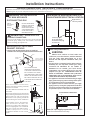
EXHAUST HOOD
FLEXIBLE GAS LINE CONNECTOR
SOAP SOLUTION
FOR LEAK DETECTION
PIPE
COMPOUND
DUCT TAPE
GLOVES
SAFETY GLASSES
4" DIAM METAL ELBOW
4" DUCT CLAMPS
OR
4" SPRING CLAMPS
(x2)
(x2)
4" DIA. FLEXIBLE METAL (SEMI-RIGID)
UL LISTED TRANSITION DUCT
(IF NEEDED)
KIT WX08X10077 (INCLUDES 2 ELBOWS)
4" DIA. METAL DUCT
(RECOMMENDED)
4" DIA. FLEXIBLE METAL (FOIL TYPE)
UL LISTED TRANSITION DUCT
(IF NEEDED.)
4" COVER PLATE (IF NEEDED)
(KIT WE1M454)
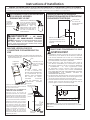
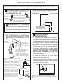
WARNING RISK OF FIRE
• To reduce the risk of severe injury or death, follow all installation instructions.
$SSOLDQFHLQVWDOODWLRQPXVWEHSHUIRUPHGE\DTXDOL¿HGLQVWDOOHU
• Install the clothes appliance according to these instructions and in accordance with local
codes. In the absence of local codes, installation must comply with National Fuel Gas
Code, ANSIZ223.1/NFPA 54 or the Canadian Natural Gas and Propane Installation Code,
CSA B149.1.
• California Safe Drinking Water and Toxic Enforcement Act.
This act requires the governor of California to publish a list of substances known to the
state to cause cancer, birth defects or other reproductive harm and requires businesses
to warn customers of potential exposure to such substances. Gas appliances can
cause minor exposure to four of these substances, namely benzene, carbon monoxide,
formaldehyde and soot, caused primarily by the incomplete combustion of natural gas
or LP fuels. Properly adjusted dryers will minimize incomplete combustion. Exposure to
these substances can be minimized further by properly venting the dryer to the outdoors.
• This appliance must be exhausted to the outdoors.
• Use only 4” rigid metal ducting for exhausting the appliance to the outdoors.
• DO NOTLQVWDOODFORWKHVGU\HUZLWKÀH[LEOHSODVWLFGXFWLQJPDWHULDOV,IÀH[LEOHPHWDO
(semi-rigid or foil-type) duct is installed, it must be UL listed and installed in accordance
with the instructions found in “Connecting The Dryer To House Vent” on page 8 of this
manual. Flexible venting materials are known to collapse, be easily crushed, and trap lint.
7KHVHFRQGLWLRQVZLOOREVWUXFWGU\HUDLUÀRZDQGLQFUHDVHWKHULVNRI¿UH
• Do not install or store this appliance in any location where it could be exposed to water
and or weather.
• Save these instructions. (Installers: Be sure to leave these instructions with the customer).
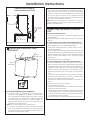
Installation
Instructions
Unitized Gas
Washer/Dryer
BEFORE YOU BEGIN
Read these instructions completely and
carefully.
•
IMPORTANT- Save these instructions for
local inspector’s use.
•
IMPORTANT- Observe all governing
codes and ordinances.
• Note to Installer - Be sure to leave these
instructions with the customer.
• Note to Customer - Keep these instructions
with your Use and Care Book for future
reference.
• Before the appliance is removed from service
or discarded, remove the washer and dryer
door.
• Inspect the dryer exhaust outlet and straighten
the outlet walls if they are bent.
• Service information and the wiring diagram
are located at the access panel.
• Do not allow children on or in the appliance.
Close supervision of children is necessary
when the appliance is used near children.
• Install the dryer where the temperature is
above 50°F (10°C) for satisfactory operation of
the dryer control system.
233D1835P001 31-16655-6 12-12 GE
D
E
S
I
G
N
C
E
R
T
I
F
I
E
D
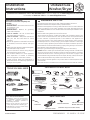
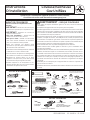
PARTS SUPPLIED
MATERIALS YOU WILL NEED
2 Rubber Washers
2 Stainer Screens/
Rubber Washers
(washers may be in water hoses)
2 Washer Hoses
1 Cable Tie
LEVEL
8" PIPE WRENCH
10" ADJUSTABLE WRENCHES
(x2)
SLIP JOINT PLIERS
FLAT BLADE SCREWDRIVER
TOOLS YOU WILL NEED
1/4” Nutdriver
Questions on Installation? Call: 1-800-GECARES (US) or Visit our Web site at: www.GEAppliances.com (US).
In Canada, call 800-561-3344 or visit www.GEAppliances.ca.
In the state of Massachusetts:
• Installation must be performed by
D TXDOL¿HGRU OLFHQVHG FRQWUDFWRU
SOXPEHU RU JDV¿WWHU TXDOL¿HG RU
licensed by the state.
•
:KHQ XVLQJ EDOOW\SH JDV VKXWRȺ
valves, they shall be T-handle type.
•
$ÀH[LEOHJDVFRQQHFWRUZKHQXVHG
must not exceed 3 feet.
Printed in Mexico

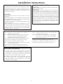
Installation Instructions
2
Step 1 Verify Your Gas Installation (see section 2).
Step 2 Prepare the Area and Exhaust for Installation of
appliance (see section 1).
Step 3 Check and Insure the Existing External Exhaust
is Clean (see section 1) and Meets Attached
,QVWDOODWLRQ6SHFL¿FDWLRQVVHHVHFWLRQ
Step 4 Remove the Foam Shipping Pads (see section 1).
Step 5 Move the appliance to the Desired Location.
6WHS/HYHO\RXUDSSOLDQFHVHHVHFWLRQ
Step 7 Connect the Gas Supply (see section 3) and check
for leaks (see section 4).
Step 8 Connect the External Exhaust (see section 7).
Step 9 Connect to plumbing facilities (see section 11).
Step 10 Connect the Power Supply (see section 5).
Step 11 Check the Operation of the Power Supply, Gas
Connections, and Venting.
Step 12 Place the Owners Manual and the Installation
Instructions in a Location Where They Will Be
Noticed By the Owner.
For Alcove or Closet Installation see section 13.
For Bathroom or Bedroom Installation see section 14.
For Mobile or Manufactured Home see section 12.
INSTALLATION REQUIREMENTS LOCATION
7KLVDSSOLDQFHPXVWEHLQVWDOOHGRQ¿UPÀRRULQJWRPLQLPL]H
YLEUDWLRQGXULQJVSLQF\FOH&RQFUHWHÀRRULQJLVEHVWEXW
ZRRGEDVHLVVXȻFLHQWSURYLGHGÀRRUVXSSRUWPHHWV)+$
standards. This appliance should not be installed on rugs
or exposed to weather.
PLUMBING
WATER PRESSURE - Must be 20 psi minimum to 120 psi
maximum.
WATER TEMPERATURE - Household water heater should be
VHWWRGHOLYHUZDWHUDWWR)WR&,17+(
WASHER when hot wash is selected.
6+872))9$/9(6%RWKKRWDQGFROGVKXWRȺYDOYHVIDXFHWV
should be supplied.
DRAIN - Water may be drained into standpipe or set tub.
Discharge height MUST NOT BE LESS THAN 30 INCHES,
DQGQRPRUHWKDQIHHWDERYHWKHEDVHRIWKHZDVKHU
Standpipe must be 1-1/2 inches minimum inside diameter
and must be open to atmosphere.
ELECTRICAL REQUIREMENTS
CAUTION: Before plugging in washer, read the following
electrical requirements.
CAUTION: For personal safety, do not use an extension
cord or adapter plug with this appliance. Do not, under any
circumstances, cut or remove the third grounding prong
from the power cord. Follow national electrical codes and
ordinances. This appliance must be supplied with the voltage
and frequency indicated on the rating plate (located at the
top of the dryer front panel), and connected to an individual,
properly grounded branch circuit, protected by a 15- or 20-
amp circuit breaker or time-delay fuse. If the electric supply
provided does not meet the above requirements, call a
licensed electrician.
• Gas clothes dryers input ratings are based on sea level
operation and need not be adjusted for operation at
or below 2000 ft. elevation. For operation at elevations
above 2000 ft., input ratings should be reduced at a rate
of 4 percent for each 1000 ft. above sea level.
• Installation must conform to local codes and ordinances
or, in their absence with the National Fuel Gas Code,
ANSI Z223.1/NFPA 54, or the Natural Gas and Propane
Installation Code, CSA B149.1.
ADJUSTING FOR ELEVATION

Installation Instructions
3
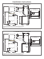
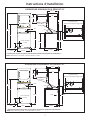
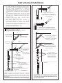
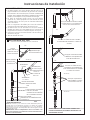
24” NOMINAL PRODUCT DIMENSIONS
74.5”
51”
Vent
Drain outlet
(rear)
4.2”
23.75”
37”
*23.75”
43”
51°
* Dimension represents door closed including handle and knobs.
NOTE: With feet set at mid position, feet can be adjusted ±.375”.
8.2”
17.9”
32.7”
33.25”
27.325”
19.1”
2”
2.75”
Gas Inlet
(Rear view of appliance)
Water Inlets
(rear)
27” NOMINAL PRODUCT DIMENSIONS
75.5”
52.9”
Vent
Drain outlet
(rear)
3.9”
µ
µ
µ
47”
51°
* Dimension represents door closed including handle and knobs.
NOTE: With feet set at mid position, feet can be adjusted ±.375”.
12.5”
µ
20.2”
30.85”
4.35”
3”
3”
Gas Inlet
(Rear view of appliance)
34.85”
Water Inlets
(rear)

Installation Instructions
4
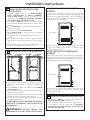
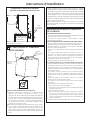
Minimum Clearance Other Than Alcove or Closet Installation
Minimum clearance to combustible surfaces and for air opening are: 0 in. clearance both sides and rear. Consideration
must be given to provide adequate clearance for installation and service.
INTERNAL DUCT
OPENING
CHECK THAT EXHAUST
HOOD DAMPER OPENS
AND CLOSES FREELY.
WALL
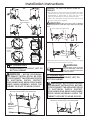
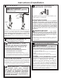
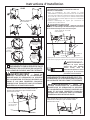
1
PREPARING FOR INSTALLATION
OF NEW APPLIANCE
DISCONNECTING GAS
REMOVING LINT FROM WALL
EXHAUST OPENING
• Remove and discard existing plastic or metal foil
transition duct and replace with UL listed transition duct.
DISCONNECT AND DISCARD OLD
FLEXIBLE GAS CONNECTOR AND
OLD TRANSITION DUCTING
MATERIAL. REPLACE WITH NEW
CSA(AGA) APPROVED FLEXIBLE
GAS LINE CONNECTOR AND UL
APPROVED TRANSITION DUCT.
TURN GAS
SHUT-OFF VALVE
TO THE OFF
POSITION.
WARNING - NEVER REUSE OLD
FLEXIBLE CONNECTORS.
7KHXVHRIROGÀH[LEOHFRQQHFWRUVFDQFDXVHOHDNVDQG
SHUVRQDOLQMXU\ $OZD\VXVHQHZ ÀH[LEOH FRQQHFWRUV
when installing gas appliances.
TILT THE APPLIANCE
SIDEWAYS AND REMOVE
THE FOAM SHIPPING PADS
BY PULLING AT THE SIDES
AND BREAKING THEM AWAY
FROM THE APPLIANCE LEGS.
BE SURE TO REMOVE ALL OF
THE FOAM PIECES AROUND
THE LEGS.
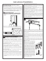
After the machine is in the home,
remove remaining packing material/
carton from washer.
DO NOT REMOVE SHIPPING ROD AT
THIS TIME.
Remove styrofoam block. Remove the
bag containing the
Washer hoses and
parts
parts from tub. Put styrofoam
block back in tub opening to hold tub
in place during the rest of installation.
0RYHZDVKHUFORVHWR¿QDOSRVLWLRQ
Make sure there is at least a 24”
clearance on right side of washer to
remove shipping bar. PULL SHIPPING
BAR OUT USING YELLOW PLASTIC
HANDLE. Keep bar so it can be
reinstalled if washer is ever moved
again.
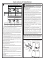
2
GAS REQUIREMENTS
WARNING
• Installation must conform to local codes and
ordinances, or in their absence, with the National
Fuel Gas Code, ANSI Z223.1/NFPA 54, or the
Natural Gas and Propane Installation Code, CSA
B149.1
• This gas dryer is equipped with a Valve & Burner
Assembly for use only with natural gas. Using
conversion kit WE25M73 for 24” Models or
WE25M74 for 27” Models, your local service
organization can convert this dryer for use with
propane (LP) gas. ALL CONVERSIONS MUST BE
MADE BY PROPERLY TRAINED AND QUALIFIED
PERSONNEL AND IN ACCORDANCE WITH LOCAL
CODES AND ORDINANCE REQUIREMENTS.
•
The appliance must be disconnected from the gas supply
piping system during any pressure testing of that system
at a test pressure in excess of 0.5 PSI (3.4 KPa).
• The appliance must be isolated from the gas supply
SLSLQJV\VWHPE\FORVLQJWKHHTXLSPHQWVKXWRȹYDOYH
during any pressure testing of the gas supply piping of
test pressure equal to or less than 0.5 PSI (3.4 KPa).
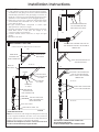
27” GAS SUPPLY CONNECTION
3”
3”
Note: 24” Gas supply connectionKDVDÀH[LEOH
hose thus dimensions will vary.
NEW HOME OR REMODELING FAUCETS/
DRAIN STANDPIPE/ELECTRICAL LOCATION
FLOOR
33”
42”
12”
Locate spigots,
drain standpipe
and electrical plug
in this area
Right side of
Laundry Center
Styrofoam Block
Shipping Bar
Yellow
Plastic
Handle
Washer Hoses
and Parts

Installation Instructions
5
GAS SUPPLY
• A 1/8-in.National Pipe Taper thread plugged tapping,
accessible for test gauge connection, must be installed
immediately upstream of the gas supply connection to
the dryer. Contact your local gas utility should you have
questions on the installation of the plugged tapping.
• Supply line is to be 1/2-in. rigid pipe and equipped with
DQDFFHVVLEOHVKXWRȺZLWKLQIWRIDQGLQWKHVDPH
room with the dryer.
8VH SLSH WKUHDG VHDOHU FRPSRXQG RU 7HÀRQ WDSH
appropriate for natural or LP gas.
<RXPXVWXVHZLWKWKLVGU\HUDÀH[LEOHPHWDO
connector
OLVWHG $16, = &6$ 7KH OHQJWK RI WKH
connector shall not exceed 3 ft.
&RQQHFW ÀH[LEOH PHWDO FRQQHFWRU WR GU\HU DQG JDV
supply.
2SHQVKXWRȺYDOYH
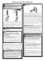
3
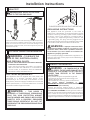
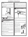
RECONNECTING GAS
Note:7KHFRQQHFWRUDQG¿WWLQJVDUHGHVLJQHGIRUXVHRQO\
on the original installation and are not to be reused for
DQRWKHUDSSOLDQFHRUDWDQRWKHUORFDWLRQ.HHSÀDUHHQGRI
adaptor free of grease, oil and thread sealant.
CAUTION: Use adapters as shown. Connector nuts must
not be connected directly to pipe threads.
/LVWHGFRQQHFWRU$16,=&6$
BACK OF
APPLIANCE
3/8” NPT INLET
FROM APPLIANCE
27” ONLY
45° ELBOW
27” ONLY
NPT
ADAPTOR
27” ONLY
NEW METAL
FLEXIBLE GAS
LINE CONNECTOR
ADAPTOR
1/8” NPT PIPE PLUG
FOR CHECKING GAS
INLET PRESSURE
SHUT-OFF VALVE
PIPE SIZE AT LEAST 1/2”
FLOOR
ITEMS NOT SUPPLIED
FLARE
TIGHTEN THE FLEXIBLE GAS LINE TO
THE ADAPTOR USING 2 ADJUSTABLE
WRENCHES.
APPLY PIPE COMPOUND
TO ALL MALE THREADS
TIGHTEN ALL CONNECTIONS USING TWO
ADJUSTABLE WRENCHES.
DO NOT OVERTORQUE GAS CONNECTIONS!
APPLY PIPE COMPOUND
TO THE ADAPTOR AND
APPLIANCE GAS INLET.
24”
INLET FROM
APPLIANCE
NEW METAL
FLEXIBLE GAS
LINE CONNECTOR
24” & 27”
27”
27”
TIGHTEN THE FLEXIBLE GAS
LINE TO THE APPLIANCE
INLET USING 2 ADJUSTABLE
WRENCHES.
24”
24”
APPLY PIPE COMPOUND TO
APPLIANCE INLET
24” & 27”
24” & 27”

Installation Instructions
4
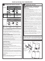
LEAK TEST
WARNING: NEVER USE AN OPEN
FLAME TO TEST FOR GAS LEAKS.
5
ELECTRICAL CONNECTION INFORMATION
ELECTRICAL REQUIREMENTS
7KLV DSSOLDQFH PXVW EH VXSSOLHG ZLWK 9 +] DQG
connected to a properly grounded branch circuit,
protected by a 15- or 20- amp circuit breaker or time-
delay fuse. If electrical supply provided does not meet the
DERYH VSHFL¿FDWLRQV LW LV UHFRPPHQGHGWKDW D OLFHQVHG
electrician install an approved outlet.
WARNING - TO REDUCE THE
RISK OF FIRE, ELECTRICAL SHOCK,
AND PERSONAL INJURY:
• DO NOT USE AN EXTENSION CORD OR AN ADAPTER
PLUG WITH THIS APPLIANCE.
Dryer must be electrically grounded in accordance
with local codes and ordinances, or in the absence
of local codes, in accordance with the NATIONAL
ELECTRICAL CODE, ANSI/NFPA NO. 70.
WARNING - THIS DRYER IS
EQUIPPED A THREE-PRONG (GROUNDING)
PLUG FOR YOUR PROTECTION AGAINST
SHOCK HAZARD AND SHOULD BE PLUGGED
DIRECTLY INTO A PROPERLY GROUNDED
THREE-PRONG RECEPTACLE. DO NOT CUT
OR REMOVE THE GROUNDING PRONG FROM
THIS PLUG.
ENSURE PROPER GROUND EXISTS BEFORE USE.
6
EXHAUST INFORMATION
WARNING - IN CANADA AND IN THE
UNITED STATES, THE REQUIRED EXHAUST DUCT
DIAMETER IS 4 IN (102mm). DO NOT USE DUCT
LONGER THAN SPECIFIED IN THE EXHAUST
LENGTH TABLE.
8VLQJH[KDXVWORQJHUWKDQVSHFL¿HGOHQJWKZLOO
• Increase the drying times and the energy cost.
• Reduce the dryer life.
$FFXPXODWHOLQWFUHDWLQJDSRWHQWLDO¿UHKD]DUG
The correct exhaust installation is YOUR
RESPONSIBILITY. Problems due to incorrect installation
are not covered by the warranty.
Remove and discard existing plastic or metal foil
transition duct and replace with UL listed transition duct.
The MAXIMUM ALLOWABLE duct length and number of
bends of the exhaust system depends upon the type of
duct, number of turns, the type of exhaust hood (wall
cap), and all conditions noted below. The maximum duct
length for rigid metal duct is shown in the table below.
GROUNDING INSTRUCTIONS
This appliance must be grounded. In the event of
malfunction or breakdown, grounding will reduce the risk
of electric shock by providing a path of least resistance
of electric current. This appliance is equipped with a
cord having an equipment-grounding conductor and
a grounding plug. The plug must be plugged into an
appropriate outlet that is properly installed and grounded
in accordance with all local codes and ordinances.
WARNING - Improper connection of the
equipment-grounding conductor can result in a risk
RIHOHFWULFVKRFN&KHFNZLWK DTXDOL¿HG HOHFWULFLDQ
or serviceman if you are in doubt as to whether the
appliance is properly grounded.
Do not modify the plug provided with the appliance. If it
ZLOOQRW¿WWKHRXWOHWKDYHDSURSHURXWOHWLQVWDOOHGE\D
TXDOL¿HGHOHFWULFLDQ
Check all connections for leaks with soapy solution or equivalent.
Apply soap solution. Bubbles indicate leaks. Leak test solution
must not contain ammonia which could cause damage to the
EUDVV¿WWLQJV,IOHDNDUHIRXQGFORVHYDOYHUHWLJKWHQWKHMRLQWDQG
repeat the soap test.

Installation Instructions
7
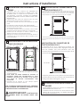
7
EXHAUST CONNECTION
THIS DRYER COMES READY FOR REAR
EXHAUSTING. IF SPACE IS LIMITED, USE
THE INSTRUCTIONS IN SECTION 9 TO
EXHAUST DIRECTLY FROM THE SIDES OR
BOTTOM OF THE CABINET.
WARNING - TO REDUCE THE
RISK OF FIRE OR PERSONAL INJURY:
• This apliancce must be exhausted to the outdoors.
• Use only 4” rigid metal ducting for the home exhaust
duct.
• 8VH RQO\ µ ULJLG PHWDO RU 8/OLVWHG ÀH[LEOH PHWDO
(semi-rigid or foil-type) duct to connect the dryer
to the home exhaust duct. It must be installed
in accordance with the instructions found in
“Connecting The Dryer To House Vent” on page 8 of
this manual.
• Do not terminate exhaust in a chimney, a wall, a ceiling,
JDVYHQWFUDZOVSDFHDWWLFXQGHUDQHQFORVHGÀRRU
or in any other concealed space of a building. The
accumulated lint could create a
potential¿UHKD]DUG
• Never terminate the exhaust into a common duct
with a kitchen exhaust system. A combination of
JUHDVHDQGOLQWFUHDWHVDSRWHQWLDO¿UHKD]DUG
• 'RQRWXVHGXFWORQJHUWKDQVSHFL¿HGLQWKHH[KDXVW
length table. Longer ducts can accumulate lint,
FUHDWLQJDSRWHQWLDO¿UHKD]DUG
• Never install a screen in or over the exhaust duct. This
ZLOOFDXVHOLQWWRDFFXPXODWHFUHDWLQJDSRWHQWLDO¿UH
hazard.
• Do not assemble ductwork with any fasteners that
extend into the duct. These fasteners can accumulate
OLQWFUHDWLQJDSRWHQWLDO¿UHKD]DUG
• Do not obstruct incoming or exhausted air.
• Provide an access for inspection and cleaning of
the exhaust system, especially at turns and joints.
Exhaust system shall be inspected and cleaned at
least once year.
DUCT TAPE OR
DUCT CLAMP
DUCT TAPE OR
DUCT CLAMP
4" METAL DUCT CUT
TO PROPER LENGTH
EXTERNAL DUCT
OPENING
For straight line installation, connect
the dryer exhaust to the external
exhaust hood using duct tape or
clamp.
GAS
INLET
PIPE
CSA (AGA) APPROVED
NEW FLEXIBLE GAS
LINE CONNECTOR
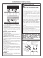
27” DRYER EXHAUST LENGTH
4" DIA.
4"
4" DIA.
4" DIA.
2-1/2"
RECOMMENDED MAXIMUM LENGTH
Exhaust Hood Types
Recommended
No. of 90º
Elbows
Rigid
Metal
Rigid
Metal
56 Feet
48 Feet
40 Feet
32 Feet
0
1
2
3
42 Feet
34 Feet
26 Feet
18 Feet
Use only
for short
run installations
24” DRYER EXHAUST LENGTH
4" DIA.
4"
4" DIA.
4" DIA.
2-1/2"
RECOMMENDED MAXIMUM LENGTH
Exhaust Hood Types
Recommended
No. of 90º
Elbows
Rigid
Metal
Rigid
Metal
43 Feet
33 Feet
24 Feet
0
1
2
36 Feet
26 Feet
16 Feet
Use only
for short
run installations
EXHAUST INFORMATION (CONT.)
EXHAUST SYSTEM CHECK LIST
HOOD OR WALL CAP
• Terminate in a manner to prevent back drafts or entry
of birds or other wildlife.
• Termination should present minimal resistance to
WKH H[KDXVW DLU ÀRZ DQG VKRXOG UHTXLUH OLWWOH RU QR
maintenance to prevent clogging.
• Never install a screen in or over the exhaust duct. This
could cause lint build up.
• Wall caps must be installed at least 12 in. above ground
level or any other obstruction with the opening pointed
down.
SEPARATION OF TURNS
For best performance, separate all turns by at least 4
ft. of straight duct, including distance between last turn
and exhaust hood.
TURNS OTHER THAN 90º
• One turn of 45º or less may be ignored.
• Two 45º turns should be treated as one 90º turn.
• Each turn over 45º should be treated as one 90º turn.
SEALING OF JOINTS
• All joints should be tight to avoid leaks. The male end of
each section of duct must point away from the dryer.
• Do not assemble the ductwork with fasteners that
extend into the duct. They will serve as a collection
point for lint.
• Duct joints can be made air and moisture-tight by
wrapping the overlapped joints with duct tape.
• Horizontal runs should slope down toward the outdoors
1/4 inch per foot
INSULATION
Duct work that runs through an unheated area or is
near air conditioning should be insulated to reduce
condensation and lint build-up.
• For every extra 90° elbow, reduce the allowable vent
system length by 10 ft.
• Two 45° elbows will be treated like one 90° elbow. For the
side exhaust installations, add one 90° elbow to the chart.
• The total vent system length includes all the straight
portions and elbows of the system (transition duct
included).

Installation Instructions
8
STANDARD REAR EXHAUST
9HQWHGDERYHÀRRUOHYHO
8
LEVELING AND STABILIZING YOUR
APPLIANCE
Level and stabilizing your appliance
&DUHIXOO\ PRYH WKH DSSOLDQFH WR LWV ¿QDO ORFDWLRQ
Gently rock the appliance into position. It is important
not to damage the rubber leveling legs when moving
\RXUDSSOLDQFHWRLWV¿QDOORFDWLRQ'DPDJHOHJVFDQ
increase appliance vibration. It may be helpful to
VSUD\ZLQGRZFOHDQHURQWKHÀRRUWRKHOSPRYH\RXU
DSSOLDQFHWRLWV¿QDOSRVLWLRQ
Note: do not use washer cover to lift the unit.
2. To ensure the appliance is level and solid on all four
OHJVWLOWWKHDSSOLDQFHIRUZDUGVRWKHUHDUOHJVDUHRȺ
the ground. Gently set the appliance back down to
allow the rear legs to self adjust.
LEVEL
SIDE-TO-SIDE.
2 LEVELING LEGS
LEVEL
FRONT-TO-BACK.
CONNECTING THE DRYER TO HOUSE
VENT
RIGID METAL TRANSITION DUCT
• For best drying performance, a rigid metal transition duct is
recommended.
• Rigid metal transitions ducts reduce the risk of crushing and
kinking.
UL-LISTED FLEXIBLE METAL (SEMI-RIGID) TRANSITION DUCT
,IULJLGPHWDOGXFWFDQQRWEHXVHGWKHQ8/OLVWHGÀH[LEOHPHWDO
(semi-rigid) ducting can be used (Kit WX08X10077).
1HYHU LQVWDOO ÀH[LEOH PHWDO GXFW LQ ZDOOV FHLOLQJV ÀRRUV RU
other enclosed spaces.
• For many applications, installing elbows at both the dryer and
the wall is highly recommended (see illustrations on page 9).
Elbows allow the dryer to sit close to the wall without kinking
and or crushing the transition duct, maximizing drying
performance.
• Avoid resting the duct on sharp objects.
UL-LISTED FLEXIBLE METAL (FOIL-TYPE) TRANSITION DUCT
• In special installations, it may be necessary to connect the
GU\HUWRWKHKRXVHYHQWXVLQJDÀH[LEOHPHWDOIRLOW\SHGXFW
$8/OLVWHGÀH[LEOHPHWDOIRLOW\SHGXFWPD\EHXVHG21/<LQ
LQVWDOODWLRQV ZKHUH ULJLG PHWDO RU ÀH[LEOH PHWDO VHPLULJLG
ducting cannot be used AND where a 4” diameter can be
maintained throughout the entire length of the transition
duct.
,Q&DQDGDDQGWKH8QLWHG6WDWHVRQO\WKHÀH[LEOHPHWDOIRLO
type) ducts that comply with the “Outline for Clothes Dryer
Transition Duct Subject 2158A” shall be used.
7RWDO OHQJWK RIÀH[LEOHPHWDOGXFW VKRXOG QRWH[FHHGIHHW
(2.4m).
• Avoid resting the duct on sharp objects.
• For best drying performance:
1. Slide one end of the duct over the clothes dryer outlet pipe.
2. Secure the duct with a clamp.
3. With the dryer in its permanent position, extend the duct to
its full length. Allow 2” of duct to overlap the exhaust pipe.
&XWRȺDQGUHPRYHH[FHVVGXFW.HHSWKHGXFWDVVWUDLJKW
DVSRVVLEOHIRUPD[LPXPDLUÀRZ
4. Secure the duct to the exhaust pipe with the other clamp.
ELBOW HIGHLY
RECOMMENDED
RECOMMENDED
CONFIGURATION
TO MINIMIZE
EXHAUST BLOCKAGE
NOTE: ELBOWS WILL PREVENT DUCT KINKING AND COLLAPSING
:LWKWKHDSSOLDQFHLQLWV¿QDOSRVLWLRQSODFHDOHYHORQ
top of back part of the washer lid and check it side to
side, then check front to back. Screw the front leveling
legs up or down to ensure the appliance is resting solid
on all four legs (no rocking or the appliance should
exist), turn the lock nuts on each leg up toward the base
of the unit and snug with a wrench.
Note: Keep the leg extension at minimum to prevent
excessive vibration. The farther out legs are extended, the
more the unit will vibrate.

Installation Instructions
9
EXHAUST TO LEFT OR RIGHT SIDE OF
CABINET
• For side ducting, remove the knockout (ONLY 1). Rotate
elbow sections so that the opening points to the side.
Preassemble 4” elbow with 4” duct. Use only 4” UL
approved rigid metal for ducting inside the dryer.
• Insert duct assembly through the side opening and
connect to the internal elbow.
WARNING
- Be sure not to pull or damage
the electrical wires inside the dryer when inserting the
duct.
DO
ELBOW HIGHLY
RECOMMENDED
DON’T
DO NOT USE
EXCESSIVE
EXHAUST
LENGTH
DO NOT SIT
APPLIANCE
ON FLEXIBLE
EXHAUST
DO NOT
CRUSH
FLEXIBLE
EXHAUST
AGAINST
WALL
9
24” MODELS ONLY:
DRYER EXHAUST TO RIGHT, LEFT OR
BOTTOM CABINET
WARNING - BEFORE PERFORMING
THIS EXHAUST
INSTALLATION, BE SURE
TO DISCONNECT THE APPLIANCE FROM
ITS ELECTRICAL SUPPLY. PROTECT
YOUR HANDS AND ARMS FROM SHARP
EDGES WHEN WORKING INSIDE THE
CABINET. BE SURE TO WEAR GLOVES.
27” MODELS ONLY:
DRYER EXHAUST TO RIGHT, LEFT OR
BOTTOM CABINET
WARNING -
BEFORE PERFORMING
THIS EXHAUST INSTALLATION, BE SURE
TO DISCONNECT THE APPLIANCE FROM
ITS ELECTRICAL SUPPLY. PROTECT
YOUR HANDS AND ARMS FROM SHARP
EDGES WHEN WORKING INSIDE THE
CABINET. BE SURE TO WEAR GLOVES.
4” UL approved rigid metal
• Apply duct tape as shown on the joint between the dryer
internal duct and the straight duct pipe.
WARNING-
Internal duct joints must be
secured with tape, otherwise
they may separate and cause
a safety hazard.
DUCT
TAPE
FLOOR
REMOVE
DESIRED
KNOCKOUT
(ONLY 1)
For downward venting, rotate elbow
sections so that elbow points downward
For downward venting, rotate elbow
sectionsm, so that elbow points downward.

Installation Instructions
10
PLUMBING INFORMATION WATER
SUPPLY REQUIREMENTS
• HOT AND COLD WATER FAUCETS – Must be within 42”
of the appliance water inlet hose connections. The
faucets must be 3/4” garden hose-type so inlet hoses
can be connected.
• WATER PRESSURE – Must be between 10 and 120
pounds per square inch with a maximum unbalance
SUHVVXUHKRWYVFROGÀRZLQJRISRXQGVSHUVTXDUH
inch.
• WATER TEMPERATURE – Water heater should be set to
GHOLYHUWR)WR&LQWKHZDVKHUZKHQ
HOT wash is selected.
6+872))9$/9(6²%RWKKRWDQGFROGZDWHUVKXWRȺ
valves (faucets) should be supplied.
• LOCATION – Do not install appliance in an area where
the temperature will fall below freezing. If appliance
is stored or transported in freezing temperatures, be
VXUHDOOZDWHUIURPWKH¿OODQGGUDLQV\VWHPVKDVEHHQ
removed.
DRAIN REQUIREMENTS
• DRAIN RATE – The drain or standpipe must be capable
RIDFFHSWLQJDGLVFKDUJHDWWKHUDWHRIJDOORQVSHU
minute.
• DRAIN HEIGHT – The drain height must be 33” minimum
DQGµPD[LPXP
10
CONNECTING TO PLUMBING
FACILITIES
If not installed, install rubber washer in one end of hot water
hose. Thread hot water hose onto connection labeled H at
top rear of washer. Hand tighten, plus an additional 1/8 turn
with pliers.
If not installed, install rubber washer in one end of cold water
hose. Thread cold water hose onto connection labeled C at
top rear of washer. Hand tighten, plus an additional 1/8 turn
with pliers.
0RYHDSSOLDQFHDVFORVHWR¿QDOORFDWLRQDVSRVVLEOHOHDYLQJ
room for you to make water, drain, electrical and vent
connections to your home.
11
C
H
HOT
HOT
HOT
HOT
COLD
COLD
COLD
COLD
NOTE: If longer drain hose
is required, order drain hose
extension kit, GE part number
WH49X301. Connect additional
drain hose (contained in kit) to
original hose with hose clamp
(contained in kit).
Insert free end of drain hose into
drain opening of your home up
to drain hose stopper (do not
remove hose stopper it prevents
siphoning). If water valves and
drain are built into wall, fasten
drain hose to one of water hoses
with cable tie provided (ribbed
side on inside). If your drains is
a standpipe, fasten drain hose
to standpipe with cable tie
provided.
EXHAUST TO LEFT OR RIGHT SIDE OF
CABINET
• Rotate elbow sections so that the opening points to the
side to which you want to vent. Preassemble 4” elbow
with 4” duct. Use only 4” UL approved rigid metal for
ducting inside the dryer.
• Connect duct assembly to the internal elbow.
WARNING
- Be sure not to pull or damage the
electrical wires inside the dryer when inserting the duct.
• Apply duct tape as shown on the joint between the
dryer internal duct and the straight duct pipe.
WARNING
-
Internal duct joints must be
secured with tape, otherwise
they may separate and cause
a safety hazard.
• STANDPIPE DIAMETER – The standpipe diameter must
be 1-1/2” minimum. There MUST be an air gap around
WKHGUDLQKRVHLQWKHVWDQGSLSH$VQXJ¿WFDQFDXVHD
siphoning action.
• SIPHON BREAK KIT – For a drain facility less than 33”
high, the hose, coupling and clamps provided in the
machine must be used and, in addition, a siphon break
MUST be installed on the back of the machine. Use
Siphon Break Kit WH49X228 and follow instructions in
the kit.

Installation Instructions
11
14
BATHROOM OR BEDROOM INSTALLATION
• The appliance MUST be vented to the outdoors. See
EXHAUST INFORMATIONVHFWLRQ
• The installation must conform with local codes or,
in the absence of local codes, with the NATIONAL
ELECTRICAL CODE, ANSI/NFPA NO. 70 and
NATIONAL
FUEL GAS CODE, ANSI Z223.
12
MOBILE OR MANUFACTURED HOME
INSTALLATION
• Installation MUST conform to the MANUFACTURED
HOME CONSTRUCTION & SAFETY STANDARD,
TITLE 24, PART 32-80 or, when such standard is not
applicable, with AMERICAN NATIONAL STANDARD
FOR MOBILE HOME, ANSI/NFPA NO. 501B.
• The appliance MUST be vented to the outdoors with
the termination securely fastened to the mobile home
structure.
• The vent MUST NOT be terminated beneath a mobile or
manufactured home.
• The vent duct material MUST BE METAL.
• KIT 14-D346-33 MUST be used to attach the appliance
securely to the structure.
• The vent MUST NOT be connected to any other duct, vent, or
chimney.
• Do not use sheet metal screws or other fastening
devices which extend into the interior of the exhaust
vent.
• Provide an opening with a free area of at least 25 sq. in. for
introduction of outside air into the dryer room.
13
ALCOVE OR CLOSET INSTALLATION
• If your appliance is approved for installation in an alcove
or closet, it will be stated on a label on the appliance
back.
• The dryer MUST be vented to the outdoors. See the EXHAUST
INFORMATION section.
• Do not install this appliance with less than the minimum
clearances shown above.
• The closet should be vented to the outdoors to prevent gas
pocketing in case of a gas leak in the supply line.
• No other fuel-burning appliance shall be installed in the same
closet with the appliance.
CONSIDERATION MUST BE GIVEN TO PROVIDE
ADEQUATE CLEARANCES FOR INSTALLATION
AND SERVICE.
WARNING: DO NOT INSTALL THIS
APPLIANCE IN A CLOSET WITH A SOLID DOOR.
1”
0”
0”
0”
1”
DOOR VENTILATION OPENING (27”
MODELS)
A minimum of 120 square inches of opening, equally
divided at top and bottom, is required. Air openings are
required to be unobstructed when a door is installed. A
louvered door with equivalent air openings for the full
length of the door is acceptable.
When louvers or registers are placed in door openings,
the free air openings of the louvers or registers must
equal 120 square inches.
DOOR VENTILATION OPENING (24”
MODELS)
A minimum of 72 square inches of opening is required. Air
openings are required to be unobstructed when a door is
installed. A louvered door with equivalent air openings for
the full length of the door is acceptable.
When louvers or registers are placed in door openings,
the free air openings of the louvers or registers must
equal 72 square inches.
6T,Q
6T,Q
27” Model
48 Sq. In.
24 Sq. In.
24” Model

Installation Instructions
12
15
SERVICING
WARNING- LABEL ALL WIRES PRIOR TO DISCONNECTION WHEN SERVICING
CONTROLS. WIRING ERRORS CAN CAUSE IMPROPER AND DANGEROUS OPERATION
AFTER SERVICING/INSTALLATION.
For replacement parts and other information, refer to Owner’s Manual for servicing phone numbers.
REGISTER YOUR NEW APPLIANCE TO RECEIVE ANY
IMPORTANT PRODUCT NOTIFICATIONS.
Please go to www.GEAppliances.com or mail in your
Product Registration Card.
)RUTXHVWLRQVRQLQVWDOODWLRQFDOO86RU
&DQDGD

233D1835P001 31-16655-6 12-12 GE
AVERTISSEMENT -
RIESQUE D’INCENDIE
• Pour réduire les risques de blessures graves ou de mort, suivez les instructions
d’installation.
/·LQVWDOODWLRQGHO·DSSDUHLOGRLWrWUHIDLWHSDUXQHSHUVRQQHTXDOL¿pH
• Installez l’appareil selon ces instructions et conformément aux normes locales. Dans
l’absence de normes locales, l’installation doit être conforme à la Norme Nationale
sur le Gaz et le Combustible, ANSIZ223.1/NFPA 54 ou la Norme Nationale Canadienne
sur le Gaz Naturel et le Propane, CSIB149.1.
•
Les appareils à gaz peuvent causés une exposition mineur à quatre deces substances,
benzène, monoxyde de carbone, formaldéhyde et suie, causée principalement par
la combustion incomplète du gaz naturel ou des fuels LP. Proprement ajustées, les
sécheuses minimiseront la combustion incomplète. L’exposition à ces substances peut
êtreminimisée en ventilant correctement la sécheuse vers l’extérieur.
• Cette sécheuse doit avoir un système d’échappement vers l’extérieur.
• Utilisez seulement des conduits rigides en métal de 4” pour la canalisation de la
sécheuse vers l’extérieur.
1(3$6LQVWDOOHUXQHVpFKHXVHDYHFGHVFRQGXLWVÀH[LEOHVHQSODVWLTXH6LOHVFRQGXLWV
ÀH[LEOHVGHPpWDOVHPLULJLGHRX HQ DOXPLQLXP VRQW LQVWDOOpV LOV GRLYHQWrWUH 8/
et installés conformément aux instructions trouvées dans « Branchez La Sécheuse
Aux Conduits de la Maison » de la page 8 de ce manuel. Les matériaux des conduits
ÀH[LEOHVVRQWFRQQXVSRXUVHIHQGUHV·pFUDVpVHWrWUHGHVSLqJHVjSHOXFKHV&HV
FRQGLWLRQVIHURQWREVWDFOHDXÀX[G·DLUGHODVpFKHXVHHWDXJPHQWHURQWOHVULVTXHV
d’incendie.
• N’installez pas et n’entreposez pas cet appareil dans un endroit où il pourrait être
exposé à l’eau ou au climat.
•
*DUGH]OHVLQVWUXFWLRQVO·LQVWDOODWHXUGRLWV·DVVXUHUGHODLVVHUFHVLQVWUXFWLRQVFKH]
OHFOLHQW
Instructions
D’Installation
Laveuse/Sécheuse
*D]8QL¿pHV
Question sur l’installation? Appelez au 800.561.3344 (Canada)
Ou visitez notre site web: www.electromenagersge.ca.
AVANT DE COMMENCER
Lisez les instructions complètement et avec
attention.
•
IMPORTANT- Gardez ces instructions pour
une utilisation possible par un réparateur local.
•IMPORTANT- Respecter les normes en
vigueur et ordonnances.
• Note pour l’installateur – $VVXUH]YRXV GH
laisser ces instructions avec le client.
• Note pour le client – Gardez ces instructions
avec votre manuel d’utilisation et d’entretien
pour une consultation future possible.
• Avant que l’appareil soit déplacé après
réparation ou pour être jeté, enlevez les portes
de la laveuse et de la sécheuse.
• Contrôlez les sorties d’échappement et redressez
l’installation sur le mur si elle est tordue.
• Les informations de réparation et le diagramme
des conduits sont situés sur le tableau d’accès.
• Empêchez les enfants d’être sur ou dans
l’appareil. Une supervision proche des enfants
est nécessaire lorsque l’appareil est utilisé.
,QVWDOOH] O·DSSDUHLO R OD WHPSpUDWXUH HVW HQ
GHVVRXVGH)&SRXUXQIRQFWLRQQHPHQW
satisfaisant du système de contrôle.
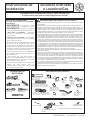
PIECES FOURNISES
2 RONDELLES EN
CAOUTCHOUC
RONDELLES
ENCAOUTCHOUC
(LES JOINTS PEUVENT ETRE
DANS LES TUYAUX A EAU)
2 TUYAUX DE LA LAVEUSE
1 COLLIER EN
PLASTIQUE
MATERIAL NECESSAIRE
2 PINCES DE
TUYAU 4”
OU 2 PINCES
TENDEUR 4”
78<$8)/(;,%/((10(7$/6(0,5,*,'(
8/'(',$0µ6,1(&(66$,5(.,7
:;;&28'(6,1&/86
TUYAU EN METAL DE
',$0µ5(&200(1'(
TUYAU FLEXIBLE EN METAL
6(0,5,*,'(8/'(',$0
µ6,1(&(66$,5(
COUDE DE
METAL DE
DIAM 4”
CAPUCHON
D’ECHAPPEMENT
BRANCHEMENT
FLEXIBLE A GAZ
SOLUTION DE SAVON POUR
LA DETECTION DES FUITES
COMPOSE
TUYAU
ROULEAU ADHESIF
POUR TUYAU
CACHE DE PROTECTION
6,1(&(66$,5('(Ý
.,7:(0
GANTS
LUNETTES DE
SECURITE
72851(9,6$'28,//(óµ
72851(9,63/$7PINCE
NIVEAU
CLE A MOLETTE 10”
CLE A PIPE 8”
OUTILS A UTILISER
[

Instructions d’Installation
2
(WDSH 9pUL¿H]YRWUH,QVWDOODWLRQGH*D]YRLUVHFWLRQ
Etape 2 Préparez la Zone et l’Echappement pour
O·,QVWDOODWLRQGHO·1RXYHOOH$SSDUHLOYRLUVHFWLRQ
(WDSH 9pUL¿H]HW$VVXUH]O·(FKDSSHPHQW([LVWDQW
([WHUQHTX·LOVRLW3URSUHYRLUVHFWLRQHWOHV
6SpFL¿FDWLRQVG·,QVWDOODWLRQ&LMRLQWHVYRLU
VHFWLRQ
Etape 4 Enlevez la Mousse de Rembourrage de Transport
YRLUVHFWLRQ
Etape 5 Déplacez l’appareil au Lieu Désiré.
(WDSH 1LYHOH]O·DSSDUHLOYRLUVHFWLRQ
(WDSH %UDQFKH]OHJD]YRLUVHFWLRQHWYpUL¿H]OHV
IXLWHVVHFWLRQ
(WDSH %UDQFKH]O·(FKDSSHPHQW([WHUQHYRLUVHFWLRQ
(WDSH5DFFRUGH]DXV\VWqPHGHSORPEHULHYRLUVHFWLRQ
(WDSH%UDQFKH]O·DSSDUHLODX&RXUDQW(OHFWULTXHYRLU
VHFWLRQ
(WDSH9pUL¿H]OH)RQFWLRQQHPHQWGX&RXUDQW(OHFWULTXH
du Branchement du Gaz et la Ventilation.
Etape 12 Placez le Manuel de l’Utilisateur et les Instructions
d’Installation dans un Lieu Où Ils Seront Trouvés
Par le Propriétaire
Pour le Renfoncement ou l’Installation dans un Meuble,
voir section 13.
Pour l’installation dans une salle de bain ou une
chambre, voir section 14.
Pour l’installation dans un mobile home, voir section 12.
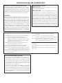
CONDITIONS D’INSTALLATION DE
L’EMPLACEMENT
Cet appareil doit être installé sur un sol solide pour minimiser
les vibrations durant le cycle d’essorage. Le sol en béton est
PHLOOHXUPDLVXQHEDVHHQERLVHVWVXȻVDQWH&HWDSSDUHLO
ne devrait pas être installé sur un tapis ou exposé au climat.
PLOMBERIE
PRESSION DE L’EAU – Elle doit être de 20 psi minimum et
120 psi maximum.
7(03(5$785('(/·($8²OHFKDXȺHHDXGHYRWUHPDLVRQ
GRLWrWUHFRQ¿JXUpSRXUGLVWULEXHUXQHHDXGHj)
j&'$16/$/$9(86(ORUVTXHO·HDXFKDXGHHVW
sélectionnée.
VALVES DE FERMETURE – La valve de fermeture d’eau
IURLGHHWFHOOHG·HDXFKDXGHURELQHWGRLYHQWrWUHIRXUQLHV
DRAINAGE – L’eau peut être drainée par le tuyau de rejet à
O·pJRXWRXSDUOHEDFFRQ¿JXUp/DKDXWHXUGHO·pFRXOHPHQW
NE DOIT PAS ETRE INFERIEURE A 30 POUCES, et pas plus de
6 pieds audessus de la base de la laveuse. Le tuyau de rejetà
O·pJRXWGRLWPHVXUHUSRXFHPLQLPXPjO·LQWpULHXUGX
diamètre et doit être ouverte vers l’extérieur.
CONDITIONS ELECTRIQUES
PRUDENCE: Avant de brancher la laveuse, lisez les
FRQGLWLRQVČOHFWULTXHVVXLYDQWHV.
PRUDENCE: Pour votre propre sécurité, n’utilisez
pas de rallonge ou d’adaptateur avec cet appareil.
Ne coupez pas ni enlevez la troisième dent de la prise
électrique correspondant à la masse. Suivez les normes
électriques nationales pour le voltage et la fréquence
LQGLTXpVVXUODSODTXHGHFRQYHUVLRQVLWXpHDXGHVVXVGH
ODVpFKHXVHVXUOHWDEOHDXDYDQWHWEUDQFKH]jXQHSULVH
individuelle,correctement connectée à la terre, protégée par
GLVMRQFWHXUGHRXDPSRXXQIXVLEOHjUHWDUGHPHQW
6LO·LQVWDOODWLRQpOHFWULTXHQHUpSRQGSDVDX[FRQGLWLRQVFL
GHVVXVDSSHOH]XQpOHFWULFLHQTXDOL¿p
/HV FODVVL¿FDWLRQV GX JD] G·HQWUpH G·XQH VpFKHXVH
à gaz sont basées sur le fonctionnement au niveau
de la mer et aucun ajustement n’est nécessaire pour
fonctionner à une altitude de 2000 pieds ou moins.
Pour un fonctionnement aux altitudes plus élevées que
SLHGV OHV FODVVL¿FDWLRQV G·HQWUpH GRLYHQW rWUH
UpGXLWHVGHSRXUFKDTXHSLHGVDXGHVVXVGX
niveau de la mer.
• L’installation doit être conforme aux normes ou
RUGRQQDQFHV ORFDX[ RX GDQV O·DEVHQFH GH FHX[
ci, conforme à la Norme Nationale sur le Gaz et le
Combustible, ANSIZ223.1/NFPA 54 ou la Norme
Nationale Canadienne sur le Gaz Naturel et le Propane,
CSIB149.1.
AJUSTEMENT POURL’ALTITUDE

Instructions d’Installation
3
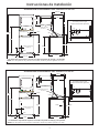
DIMENSIONS NOMINALES DU PRODUIT 24”
74.5”
51”
Ventilation
Arrivée d’eau
arrière
Sortie drainage
arrière
4.2”
23.75”
37”
*23.75”
43”
51°
* Dimensions lorsque les portes sont fermées incluant les poignées et les boutons.
NOTE: Dimensions en pieds, correspondant á ± 375”.
8.2”
17.9”
32.7”
27.325”
19.1”
DIMENSIONES NOMINALES DU PRODUIT 27”
75.5”
52.9”
3.9”
26.8”
36.5”
*26.7”
47”
51°
* Dimensions lorsque les portes sont fermées incluant les poignées et les boutons
NOTE: Dimensions en pieds, correspondant á ± 375”.
12.5”
18.6”
20.2”
30.85”
4.35”
Ventilation
Arrivée d’eau
arrière
Sortie drainage
arrière
2”
3”
2.75”
3”
Entrée du gaz
9XHGHO·DUULqUHGHO·DSSDUHLO
Entrée du gaz
9XHGHO·DUULqUHGHO·DSSDUHLO
33.25”
34.85”

Instructions d’Installation
4
1
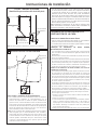
SE PREPARER POUR L’INSTALLATION
D’UN NOUVEL APPAREIL
DEBRANCHEZ LE GAZ
ENLEVER LES PELUCHES DE
L’OUVERTURE D’ECHAPPEMENT DU
MUR
(QOHYH]HWGpEDUUDVVH]YRXVGHVIHXLOOHVGHPpWDOHWGH
SODVWLTXHGXWX\DXGHWUDQVLWLRQHWUHPSODFH]OHDYHFXQ
tuyau de transition UL.
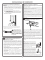
Après que la machine soit dans votre
maison, enlevez les matériaux restants
et cartons de la laveuse.
N’ENLEVEZ PAS LES BARRES DE
TRANSPORT POUR LE MOMENT.
Enlevez le bloc de mousse de
polystyrène.Enlevez le sac contenant les
Tuyaux de jonction et les pièces du bac.
Mettez le bloc de mousse de polystyrène
dans l’ouverture du bac pour tenir le bac
en place durant lereste de l’installation.
Déplacez la laveuse vers la position
¿QDOH$VVXUH]YRXVTX·LO\DLWDXPRLQV
24” d’espace à droite de la laveuse
pour enlever les barresde transport.
TIREZ LES BARRES DE TRANSPORT
VERS L’EXTERIEUR UTILISANT LA
POIGNEE JAUNE EN PLASTIQUE.
Gardez les barres au cas où vous
devriez la réinstallé ou si la laveuse est
déplacée plus tard.
Espace Minimum Autre Que le Renfoncement ou l’installation Dans un Meuble
L’espace minimum pour les surfaces combustibles et l’ouverture d’air sont: 0 in. d’espace de chaque coté et à l’arrière. Les
considérations doivent être données pour fournir un espace adéquat pour l’installation et la réparation.
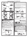
PENCHER L’UNITÉ VERS
LE CÔTÉ ET ENLEVER LES
PROTECTIONS DE TRANSPORT
DE STYROMOUSSE EN LES
BRISANT VERS L’EXTÉRIEUR
DES PATTES DE L’UNITÉ.
S’ASSURER D’ENLEVER
TOUS LES MORCEAUX DE
STYROMOUSSE AUTOURS
DES PATTES.
OUVERTURE
INTERNE DU
TUYAU
VERIFIEZ QUE LA CLE
D’ECHAPPEMENT
OUVRE ET FERME
LIBREMENT
MUR
NOUVELLE MAISON OU NOUVEAUX
ROBINETS/CANALISATION D’ÉVACUATION/
EMPLACEMENT ÉLECTRIQUE
Barre de
transport
Poignée jaune
en plastique
Tuyaux de
jonction et
pièces
Bloc de mousse
de polystyrène
FLOOR
33”
42”
12”
Placez la robinetterie, le
tuyau d’évacuation et la
connexion électriqu à cet
endroit.
Côté droite
du centre de
ODYDJHODYHXVH
VpFKHXVH
sol
AVERTISSEMENT
-
NE JAMAIS
REUTILISER DES BRANCHEMENTS FLEXIBLES
ANCIENS
/´XWLOLVDWLRQGHEUDQFKHPHQWV ¾H[LEOHVDQFLHQV
peut causer desfuites et des blessures personnelles.
7RXMRXUV XWLOLVHU GHVEUDQFKHPHQWV ¾H[LEOHV QHXIV ORUVTXH
vous installez desappareils à gaz.
'(%5$1&+(=(7'(%$55$66(=
VOUS DES ANCIENS TUYAUX A
GAZ FLEXIBLES ET LES ANCIENS
MATERIAUX DE TRANSISTION.
5(03/$&(=/(6 $9(& 81
BRANCHEMENT A GAZ FLEXIBLE
$335289( &6$ $*$ 1(8) (7
UN TUYAU DE TRANSITION UL
AUSSI APPROUVE.
TOURNEZ
LA VALVE DE
FERMETURE
A GAZ A LA
POSITION FERME
2
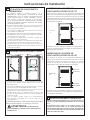
CONDITIONS CONCERNANT LE GAZ
AVERTISSEMENT
• L’installation doit être conforme aux normes locales et
ordonnances, ou en absence de ces derniers, conforme
à la Norme Nationale sur le Gaz et le Combustible,
ANSIZ223.1/NFPA 54 ou la Norme Nationale Canadienne
sur le Gaz Naturel et le Propane, CSIB149.1.
• Cette sécheuse à gaz est équipée d’une Valve et
d’un Bruleur Assemblés pour l’utilisation unique de
gaz naturel. Utilisant le kit de conversion WE25M73
µ:(0 µ YRWUH RUJDQLVDWLRQ ORFDOH
de réparation pourra convertir cette sécheuse à
O·XWLOLVDWLRQ GX SURSDQH /3 7287( &219(56,21
DOIT ETRE REALISEE PAR UNE PERSONNE QUALIFIEE
CONFORMEMENT AUX NORMES LOCALES ET
ORDONNANCES REQUISES.
• La sécheuse doit être débranchée du système d’arrivéede
gaz durant les tests de pression de ce même système pour
XQWHVWGHSUHVVLRQVXSpULHXUj36,.SD
• La sécheuse doit être isolée de l’arrivé de gaz en fermantles
robinets durant tout test de pression du gaz d’un test de
SUHVVLRQpJDOHRXLQIHULHXUj36,.SD
27” CONNEXION D’ALIMENTATION EN GAZ.
3”
3”
REMARQUE: 24” a une connexion d’alimentation en
JD]DYHFFRQGXLWÀH[LEOHGRQFOHVGLPHQVLRQVYRQWrWUH
GLȺHUHQWHV

Instructions d’Installation
5
ALIMENTATION DE GAZ
•
Un rouleau adhésif pour branchement à gaz de 1/8 in.,
accessible pour des tests de calibrage du branchement,
doit être installé immédiatement en amont du
branchement d’alimentation en gaz à la sécheuse.
Contactez l’entreprise de gaz la plus proche si vous avez
des questions sur l’installation du rouleau adhésif pour
prise.
• Le branchement d’alimentation doit être un tuyau
rigide de ½ in. et équipé avec une valve de fermeture
accessible à 6 ft. de distance, et dans la même pièce
que la sécheuse.
8WLOLVH] OH FRPSRVp SRXU WX\DX RX OH VFRWFK 7pÀRQ
approprié pour le gaz naturel et LP.
• Vous devez utiliser avec cette sécheuse un
EUDQFKHPHQW ÀH[LEOH HQ PpWDO OLVWp FRPPH
branchement ANSI Z21.24 / CSA6.10. La longueur de
ce branchement ne devrait pas excéder 3 ft.
&RQQHFWH] OH EUDQFKHPHQW ÀH[LEOH HQ PpWDO j OD
sécheuse et à l’alimentation en gaz.
• Ouvrez la valve de fermeture.
3
REBRANCHER LE GAZ
Note: Le connecteur et les raccords sont conçus pour être
utilisés uniquement sur l’installation d’origine et ne doivent
pas être réutilisés pour un autre appareil ou à un autre endroit.
*DUGH]IXVpH¿QGHO·DGDSWDWHXUVDQVJUDLVVHKXLOHHWXQSURGXLW
d’étanchéité.
ATTENTION: Utiliser des adaptateurs, comme illustré. Ecrous
FRQQHFWHXUGRLWQHSDVrWUHFRQQHFWpGLUHFWHPHQWj¿OHWDJHV
Branchement listé ANSI Z21.24 / CSA 6.10
RETOUR DE
L‘APPAREIL
3/8” NPT ENTREE
DE L‘APPAREIL 27”
SEULEMENT
45° COUDE
27” SEULEMENT
NPT
ADAPTATEUR
27” SEULEMENT
BRANCHEMENT NEUF
FLEXIBLE A GAZ EN
METAL
ADAPTATEUR
PRISE TAYEAU NPT
1/8” POUR VERIFIER
LA PRESSION DU GAZ A
ENTRANT
VALVE DE FERMETURE
TAILLE DU BRANCHEMENT D’AU
MOINS 1/2”
PLANCHER
N’EST PAS FOURNI
FLARE
SERRER LA LIGNE DE BRANCHEMENT A
GAZ FLEXIBLE A L’ENTREE A GAZDE LA
SECHEUSE EN UTILISANT 2 CLÉSÀ MOLETTE
APPLIQUEZ LE
COMPOSED’ ÉTANCHÉITÉ
DES TUYAUTERIES
SURTOUS LES FILETS
DESPARTIES MÂLE
SERRER TOUS LES CONNECTEURS EN UTILISANT
2 CLÉS À MOLETTE. NE PAS SUR-SERREZ PAS LES
CONNECTEURS DE GAZ.
APPLIQUEZ LE COMPOSE D’
ÉTANCHÉITÉ DES TUYAUTERIES À
L’ADAPTATEURET LE ENTRÉE DU GAZ
DE LA SECHEUSE
24”
L’ENTREE A GAZ
DE LA SECHEUSE
BRANCHEMENT
NEUF FLEXIBLE A
GAZ EN METAL
24” & 27”
27”
27”
SERRER LA LIGNE DE
BRANCHEMENT A GAZ
FLEXIBLE A L’ENTREE A GAZ DE
LA SECHEUSE EN UTILISANT 2
CLÉS À MOLETTE
24”
24”
APPLIQUEZ LE COMPOSE
D’ ÉTANCHÉITÉ DES
TUYAUTERIES À L’ ENTRÉE A
GAZ DE LA SECHEUSE
24” & 27”
24” & 27”

Instructions d’Installation
6
5
INFORMATION CONCERNANT LE
BRANCHEMENT ELECTRIQUE
4
TEST DE LA FUITE
5
INFORMATION CONCERNANT LE
BRANCHEMENT ELECTRIQUE
CONDITIONS ELECTRIQUES
Cet appareil doit être branché à une prise électrique 120V,
60Hz, et correctement connectée à la terre, protégée par
GLVMRQFWHXUGHRXDPSRXXQIXVLEOHjUHWDUGHPHQW
6LO·LQVWDOODWLRQpOHFWULTXHQHUpSRQGSDVDX[VSpFL¿FDWLRQV
FLGHVVXVDORUVDSSHOH]XQpOHFWULFLHQTXDOL¿p
AVERTISSEMENT - POUR
REDUIRE LES RISQUES D’INCENDIE,
DE DECHARGE ELECTRIQUE ET DE
BLESSURE PERSONNELLE :
• N’UTILISEZ PAS DE RALONGE ELECTRIQUE OU
D’ADAPTATEUR AVEC CET APPAREIL.
Cet appareil doit être branché á la terre
conformément aux normes locales et ordonnances,
ou dans l’absencede normes locales, conformément
AUX NORMES ELECTRIQUES NATIONALES, ANSI/NFPA
NO. 70.
AVERTISSEMENT
- LA SECHEUSE
EST EQUIPPEE D’UNE PRISE TRIPHASEE
(MASSE) POUR VOTRE PROTECTION CONTRE
LES RISQUES DE DECHARGES ELECTRIQUES
ET DEVRAIT ETRE BRANCHEE DIRECTEMENT
AU RECEPTAVLE TRIPHASE. NE COUPEZ PAS ET
N’ENLEVEZ PAS LA DENT CORRESPONDANT A
LA MASSE SUR LA PRISE.
$6685(=928648·,/(;,67(81(35,6($/$
TERRE AVANT UTILISATION
AVERTISSEMENT
: NE JAMAIS
UTILISER UNE FLAMME POUR TESTER S’IL Y A
DES FUITES DE GAZ.
9pUL¿H]V·LO\DGHVIXLWHVjWRXVOHVEUDQFKHPHQWVDYHF
du savon ou un produit équivalent. Appliquez la solution
de savon. Des bulles indiquent une fuite. Le test de la
fuite ne doit pas contenir d’ammoniac car ceci pourrait
causer des dégâts aux accessoires en cuivre. Si des
fuites sont rencontrées, resserrez les joints, et répétez le
test du savon.
OUVRIR
LA VALVE
A GAZ
6
INFORMATION D’ECHAPPEMENT
AVERTISSEMENT - AU CANADA ET AUX
USA, LE DIAMETRE DU TUYAU D’ECHAPPEMENT REQUIS EST 4”
(102mm). N’UTILISEZ PAS DE TUYAU PLUS GRAND QUE LA TAILLE
SPECIFIEE DANS LE TABLEAU DE LONGUEUR D’ECHAPPEMENT.
En utilisant un tuyau d’échappement plus grand que
ODORQJXHXUVSpFL¿pHFHOD
• Augmentera le temps de séchage et les dépenses en
énergie.
• Réduira la durée de vie de la sécheuse.
• Accumulera les peluches, créant un risque potentiel
d’incendie.
L’installation correcte d’échappement est VOTRE
RESPONSABILITE. Les problèmes dus à une installation
incorrecte ne sont pas couverts par la garantie.
(QOHYH] HW GpEDUUDVVH]YRXV GHV SODVWLTXHV
existants ou du tuyau detransition en feuilles de
PpWDO HW UHPSODFH]OH SDU XQ WX\DX GH WUDQVLWLRQ
UL. La longueur de tuyau MAXIMUM AUTORISEE et
le nombre de coudes du système d’échappement
dépend du type de tuyau, du nombre decourbes, du
W\SHGXFDSXFKRQG·pFKDSSHPHQWERXFKRQGXPXU
HWGHVFRQGLWLRQVSUpVHQWpHVFLGHVVRXV/DORQJXHXU
maximum du tuyau pour les tuyaux rigide en métal
est montrée dans le tableau cidessous.
INSTRUCTIONS DE MASSE
Cet appareil doit être mis à la terre. En cas de défaillance
ou de panne, la terre réduira le risque de choc électrique en
fournissant un chemin de moindre résistance du courant
électrique. Cet appareil est équipé d’un cordon comportant
XQFRQGXFWHXUGHWHUUHHWXQH¿FKHGHWHUUH/D¿FKHGRLWrWUH
branchée dans une prise appropriée, correctement installée
et mise en conformité avec tous les codes locaux une des
ordonnances.
AVERTISSEMENT
Une mauvaise
connexion du conducteur de terre peut entraîner un risque
de choc électrique. Consultez un électricien ou un réparateur
TXDOL¿pVLYRXVrWHVGDQVOHGRXWHTXDQWjVDYRLUVLO·DSSDUHLO
est correctement mise à la terre.
1HSDVPRGL¿HUOD¿FKHIRXUQLHDYHFO·DSSDUHLOVLHOOHQ·HQWUH
pas dans la prise, faites installer une prise adéquate par un
pOHFWULFLHQTXDOL¿p

Instructions d’Installation
7
6
INFORMATION D’ECHAPPEMENT (CONT.)
LISTE DE CONTROLE DU SYSTEME D’ECHAPPEMENT
CAPUCHON OU GRILLE DU MUR
• Protégez la sortie de votre canalisation dans le but d’éviter les
appels d’air ou l’entrée d’un oiseau et autres animaux sauvages.
&HWWHSURWHFWLRQGHYUDLWSUpVHQWHUXQHUpVLVWDQFHPLQLPXPDXÀX[
d’air échappement et devrait exiger peu ou pas de maintenance
pour éviter l’encrassement.
• Ne Jamais installez d’écran dans ou sur le tuyau d’échappement.
Ceci pourrait conduire à la création de peluches. Les grilles du mur
GRLYHQWrWUHLQVWDOOpHVDXPRLQVjLQ$XGHVVXVGXQLYHDXGX
VRORX jFHWWH GLVWDQFHDXGHVVXV GHQ·LPSRUWHTXHODXWUHREMHW
pouvant faire obstruction à cette sortie.
SEPARATION DES COUDES
Pour une meilleure performance, séparez tous les coudes d’au moins
4 ft. De tuyauterie droite, incluant la distance entre le dernier coude et
le capuchon du système d’échappement.
COUDES AUTRES QUE 90º
• Un coude de 45º ou moins peut être ignoré
• Deux coudes de 45º devraient être traités comme un coude de 90º.
• Chaque coude de plus de 45º devrait être traité comme un coude
de 90º.
SCELLAGE DES JOINTS
• Tous les joints devraient être serrés pour éviter les fuites. L’extrémité
male de chaque section de tuyau doit être dirigée vers l’extérieur
de la sécheuse.
• N’assemblez pas la canalisation avec des agrafes qui entrent dans
le tuyau. Elles serviront à la création de peluches.
• Les joints de tuyaux peuvent être faits d’air et de moisissures en
emballant le chevauchement de joints avec le rouleau adhésif de
tuyau.
• Les trajets horizontaux devraient descendre vers l’extérieur de ½
pouce par pied.
ISOLATION
/D FDQDOLVDWLRQ TXL FRXUW j WUDYHUV XQH ]RQH QRQ FKDXȺpH RX
qui est près de l’air conditionné devrait être isolée pour réduire la
condensation et la création de peluches.
7
BRANCHEMENT DE L’ECHAPPEMENT
L’ECHAPPEMENT ARRIERE FAIT PARTIE DE CETTE SECHEUSE.
SI VOTRE ESPACE EST LIMITE, UTILISEZ LES INSTRUCTIONS
DE LA SECTION 9 POUR AVOIR UN SYSTEME D’ECHAPPEMENT
LATERAL OU PAR LE BAS DU COFFRAGE DE LA MACHINE.
AVERTISSEMENT
- POUR REDUIRE
LES RISQUES D’INCENDIE OU DE BLESSURES
PERSONNELLES :
•
Cet appareil doit avoir un système d’échappement
versl’extérieur.
• Utilisez seulement de la tuyauterie rigide en métal de
4” pour le tuyau d’échappement de la maison.
• Utilisez seulement un tuyau rigide en métal ou un tuyau
ÀH[LEOH8/VHPLULJLGHRXHQDOXPLQLXPSRXUEUDQFKHU
la sécheuse au tuyau d’échappement de la maison. Il
doit être installé conformément aux instructions trouvé
en page 7 de ce manuel sous “Brancher La Sécheuse
au Conduit d’Aération de la Maison”.
•
1HPHWWH]SDV¿QjO·pFKDSSHPHQWSDUXQHFKHPLQpH
un mur, un toit, un conduit de gaz, un petit espace, un
grenier, sous un plancher non fermé, ou dans n’importe
quel autre espace dissimulé de votre bâtiment. La charpie
accumulée pourrait créer un risque potentiel d’incendie.
1HMDPDLVPHWWUH¿QjO·pFKDSSHPHQWSDUXQWX\DX
commun avec le système d’échappement de la
cuisine. Une combinaison de graisses et de peluches
créer un risque potentiel d’incendie.
• N’utilisez pas de tuyau plus grand que ce qui est
VSpFL¿pGDQVOHWDEOHDXGHJUDQGHXUG·pFKDSSHPHQW
Des tuyaux plus grands peuvent permettre
l’accumulation de peluches et créer unrisque
d’incendie potentiel.
• Ne jamais installer un écran dans ou sur le tuyau
d’échappement. Ceci causera l’accumulation de
peluches,créant un risque potentiel d’incendie.
N’assemblez pas la canalisation avec des agrafes
qui entrent dans le tuyau. Ces agrafes peuvent créés
l’accumulation depeluches, créant un risque d’incendie.
N’obstruez pas l’air entrant et sortant.
Mettez à disposition un accès pour inspecter et nettoyer
le système d’échappement, spécialement aux coudes
et aux joints. Le système d’échappement devrait être
inspecté et nettoyé aumoins une fois par an.
SCOTCH DE TUYAU
OU PINCE
OUVERTURE
EXTERNE DU
CONDUIT
TUYAU EN METAL
4” COUPE A LA
LONGUEUR
APPROPRIEE
SCOTCH
DETUYAU OU
PINCE
BRANCHEMENT NEUF
FLEXIBLE A GAZ EN METAL
$335289(&6$$*$
TUYAU D’ENTREE
A GAZ
Pour une installation en ligne droite,
branchez le système d’échappement de la
sécheuse au conduit externed’échappement
en utilisant du scotch ouune pince.
• Pour chaque coude additionnel de 90°, réduire de 10 pieds la
longueur totale permise du système de ventilation.
• Deux coudes de 45° devront être considérés comme un coude de
90°.
• Pour la ventilation latérale, ajouter un coude de 90° au tableau.
• La longueur totale du système de ventilation inclut toutes les portions
GURLWHVHWWRXVOHVFRXGHVGXV\VWqPHOHWX\DXGHWUDQVLWLRQLQFOXV
0
1
2
3
27” LONGUEUR D’ECHAPPEMENT
LONGUEUR MAXIMUM RECOMMANDEE
RECOMMANDEE
Utilise seulement pour les
Installations de petites distances
4”
µ
Métal rigide
Nº de coudes
à 90º
Métal rigide
56 Feet
48 Feet
40 Feet
32 Feet
42 Feet
34Feet
26 Feet
18 Feet
4” DIA.
4” DIA.
4” DIA.
0
1
2
24” LONGUEUR D’ECHAPPEMENT
LONGUEUR MAXIMUM RECOMMANDEE
RECOMMANDEE
Utilise seulement pour les
Installations de petites distances
4” µ
Métal rigide
Nº de coudes
à 90º
Métal rigide
43 Feet
33 Feet
24 Feet
36 Feet
26 Feet
16 Feet
4” DIA.
4” DIA.
4” DIA.

Instructions d’Installation
8
ECHAPPEMENT ARRIERE STANDARD
(Ventilé au-dessous du niveau du sol)
8
METTRE A NIVEAU ET STABILISER
VOTRE APPAREIL
Mettre à niveau et stabiliser votre appareil
'pSODFH] SUXGHPPHQW O·DSSDUHLO YHUV VD SRVLWLRQ ¿QDOH
Balancez avec douceur l’appareil en position. Il est
important de ne pas endommager les pieds de nivèlement
en caoutchouc lorsque vous déplacez votre appareil vers sa
SRVLWLRQ¿QDOH/HVSLHGVHQGRPPDJpVSHXYHQWDXJPHQWHU
les vibrations de l’appareil. Il peut être utile de pulvériser
un nettoyeur de vitre sur le sol pour aider à déplacer votre
DSSDUHLOYHUVVDSRVLWLRQ¿QDOH
Note : 1·XWLOLVH]SDVODSURWHFWLRQGHODODYHXVHSRXUSRUWHUO·XQLWp
2. Pour assurer que l’appareil est à niveau et stable sur ses
quatre pieds, inclinez l’appareil vers l’avant pour que les
pieds arrière soient hors du sol. Redescendez en douceur
l’appareil pour permettre aux pieds arrières de s’ajusteront
seuls.
BRANCHER LA SECHEUSE A L’AERATION
DE LA MAISON
TUYAU RIGIDE DE TRANSITION EN METAL
• Pour les meilleures performances de séchage possibles, le tuyau de
transition rigide en métal est recommandé.
• Les tuyaux de transition rigides en métal réduisent le risque
d’écrasement et de noeuds.
TUYAU DE TRANSITION UL FLEXIBLE EN METAL (SEMI-RIGIDE)
• Si le tuyau rigide en métal ne peut pas être utilisé, alors le tuyau UL
ÀH[LEOHHQPpWDOVHPLULJLGHSHXWrWUHXWLOLVp.LW:;;
1HMDPDLVLQVWDOOHUGHWX\DXÀH[LEOHHQPpWDODXPXUVDXSODIRQG
aux sols ou autres espaces fermés.
/DORQJXHXUGXWX\DXÀH[LEOHHQPpWDOQHGHYUDLWSDVH[FpGpSLHGV
P
• Pour plusieurs applications, installer des coudes à la fois à la
VpFKHXVH HW DX PXU HVW IRUWHPHQW UHFRPPDQGp YRLU LOOXVWUDWLRQ
FLGHVVRXV /HV FRXGHV SHUPHWWHQW j O·DSSDUHLO G·rWUH SODFp SUqV
du mur sans faire de noeuds et/ou écraser le tuyau de transition,
maximisant les performances de séchage.
• Evitez de pauser le tuyau dur des objets coupants.
LE TUYAU DE TRANSITION UL FLEXIBLE EN METAL (ALUMINIUM)
• Pour des installations spéciales, il peut être nécessaire de brancher
ODVpFKHXVHjO·DpUDWLRQGHODPDLVRQXWLOLVDQWXQWX\DXÀH[LEOHHQ
PpWDO DOXPLQLXP 8Q WX\DX 8/ ÀH[LEOH HQ PpWDO VHPLULJLGH QH
peut pas être utilisé ET ceci où un diamètre de 4” peut être maintenu
tout au long du tuyau.
$X &DQDGD HW DX[ 86$ VHXOHPHQW OHV WX\DX[ ÀH[LEOHV HQ PpWDO
DOXPLQLXP TXL VH SOLHQW j ´'HVFULSWLRQ *pQpUDOH GX 7X\DX GH
Transition de la Laveuse de Vêtements du Sujet 2158A” devrait être
utilisé.
1H MDPDLV LQVWDOOHU GH WX\DX ÀH[LEOH HQ PpWDO VXU OHV PXUVOHV
plafonds, les sols ou autres espaces fermés.
/D ORQJXHXU GX WX\DX ÀH[LEOH HQ PpWDO QH GHYUDLW SDV H[FpGpH
SLHGVP
• Evitez de pauser le tuyau dur des objets coupants.
• Pour les meilleures performances possibles :
1. Faites glisser une extrémité du tuyau sur le conduit extérieur de la
sécheuse de vêtements
2. Fixez le tuyau avec une pince.
3. Ayant la sécheuse dans sa position permanente, prolongez
le tuyau vers sa longueur maximum. Laissez 2” de tuyau se
chevaucher avec le conduit d’échappement. Coupez et enlevez
l’excès de tuyau. Gardez le tuyau aussi droit que possible pour
PD[LPLVHUOHÀX[G·DLU
4. Fixez le tuyau au conduit d’échappement avec l’autre pince.
COUDE
HAUTEMENT
RECOMMANDE
CONFIGURATION
RECOMMANDEE POUR
MINIMISER LES BLOCAGE
DE CANALISATION
NOTE : LES COUDES EMPECHERONT LES NOEUDS ET LES
())21'5(0(176'8&21'8,7
$\DQW O·DSSDUHLOj VD SRVLWLRQ ¿QDOHSODFH] XQ QLYHDX
DXGHVVXVDXIRQGGXFRXYHUFOHGHODODYHXVHHWYpUL¿H]
GHFKDTXHFRWpSXLVYpUL¿H]O·DYDQWHWO·DUULqUH9LVVH]OHV
pieds de nivèlement avant pour assurer que l’appareil
UHVWH VWDEOH VXU VHV TXDWUH SLHGV QH EDODQFH] SDV
O·DSSDUHLOSRXUYpUL¿HUVDVWDELOLWpUHOHYH]OHVpFURXVGH
verrou sur chaque pied vers la base de l’unité et assurez
DYHFXQWRXUQHjJDXFKH
Note: *DUGH] O·H[WHQVLRQ GH SLHG DX PLQLPXP SRXU pYLWHUOHV
YLEUDWLRQVH[FHVVLYHV3OXVOHVSLHGVVRQWDJUDQGLVSOXV·XQLWpDGH
FKDQFHGHYLEUHU
NIVEAU DE
L’AVANT A
L’ARRIERE
NIVEAU
D’UN COTEA
L’AUTRE
PIEDS DE NIVÈLEMENT
La page charge ...
La page charge ...
La page charge ...
La page charge ...
La page charge ...
La page charge ...
La page charge ...
La page charge ...
La page charge ...
La page charge ...
La page charge ...
La page charge ...
La page charge ...
La page charge ...
La page charge ...
La page charge ...
-
 1
1
-
 2
2
-
 3
3
-
 4
4
-
 5
5
-
 6
6
-
 7
7
-
 8
8
-
 9
9
-
 10
10
-
 11
11
-
 12
12
-
 13
13
-
 14
14
-
 15
15
-
 16
16
-
 17
17
-
 18
18
-
 19
19
-
 20
20
-
 21
21
-
 22
22
-
 23
23
-
 24
24
-
 25
25
-
 26
26
-
 27
27
-
 28
28
-
 29
29
-
 30
30
-
 31
31
-
 32
32
-
 33
33
-
 34
34
-
 35
35
-
 36
36


GE GTUP240GMWW Guide d'installation
- Catégorie
- Sèche-linge électriques
- Taper
- Guide d'installation
- Ce manuel convient également à
dans d''autres langues
- English: GE GTUP240GMWW Installation guide
Documents connexes
-
GE GUD24ESSJWW Guide d'installation
-
GE DMCD330GJWC Guide d'installation
-
GE GTDX185GDCC Guide d'installation
-
GE GTUN275EMWW Guide d'installation
-
Kenmore GTUN275GM0WW Guide d'installation
-
-
-
GE DNCD450EGWC Guide d'installation
-
-