Weber 310 Manuel utilisateur
- Catégorie
- Cuisinières
- Taper
- Manuel utilisateur
Ce manuel convient également à

1
2
2
3
4
5
6
7
9
11
12
13
14
15
16
11
12
13
14
21
19
17
20
22
18
8
10
310, 320
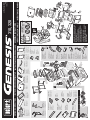
ASSEMBLY INSTRUCTIONS •
Cookbox Assembly - 1
63734 US 02/27/08
LP
US ENGLISH
UNPACKING INSTRUCTIONS •
Front Panel - 1 Drip Tray - 1 Shroud - 1 Right Side Table - 1 Left Side Table - 1 Door Handle - 2 Left Door Panel - 1 Right Door Panel - 1
Left Frame - 1 Right Frame - 1
Locking Caster - 2
Caster - 2
Rear Frame Support - 1
Bottom Tray - 1
Rear Panel - 1
Cooking Grate - 2
Knob - 3
Catch-Pan - 1
Disposable
Drip Pan - 2
Flavorizer
®
Bar - 5
HARDWARE •
Catch-Pan Holder - 1
Left Trim Assembly - 1
Side Burner - 1
Right Front Trim
Assembly - 1
Left Front Trim
Assembly - 1
Right Trim Assembly - 1
Warming Rack - 1
IMPORTANT: TO PROPERLY ALIGN FRAME
AND DOORS, ASSEMBLE GRILL ON A FLAT
AND LEVEL SURFACE.
TOOLS NEEDED:
Front Frame Support - 1
Ensemble du boîtier
de cuisson - 1
Panneau avant - 1
Plateau de recueil
des gouttes - 1
Structure - 1
Tablette latérale droite - 1
Tablette latérale
gauche - 1
Poignée de porte - 2
Panneau de porte
gauche - 1
Panneau de porte
droit - 1
Coffrage gauche - 1
Coffrage droit - 1
Ecrou de
verrouillage - 2
Ecrou - 2
Support du
châssis arrière - 1
Plateau inférieur - 1
Panneau arrière - 1
Grille de cuisson - 2
Bouton - 3
Egouttoir - 1
Egouttoir jetable - 2
Barre Flavorizer
®
- 5
MATÉRIEL
Support de l’égouttoir - 1
Ensemble de
garniture gauche - 1
Brûleur latéral - 1
Garniture avant
droite ensemble - 1
Garniture avant
gauche ensemble - 1
Ensemble de
garniture droit - 1
Grille de maintien
au chaud - 1
OUTILS NECESSAIRES:
IMPORTANT: POUR ALIGNER
CORRECTEMENT LE CHASSIS ET LES PORTES,
ASSEMBLEZ LE GRILL SUR UNE SURFACE
PLANE ET A NIVEAU.
INSTRUCTIONS POUR LE DEBALLAGE
INSTRUCTIONS DE MONTAGE
Support du
châssis avant - 1
samble de la caja de
cocción - 1
Panel delantero - 1 Bandeja de goteo - 1 Defensa - 1 Mesa lateral derecha - 1 Mesa lateral
izquierda - 1
Asa de la puerta - 2 Panel de la puerta
izquierda - 1
Panel de la puerta
derecha - 1
Bastidor izquierdo - 1 Bastidor derecho - 1
Rueda loca
con traba - 2
Rueda loca - 2
Soporte posterior
del bastidor -1
Bandeja del fondo - 1
Panel trasero - 1
Parrilla de cocción - 2
Perilla - 3
Plato recolector - 1
Bandeja de goteo
desechable - 2
Barra Flavorizer
®
- 5
HERRAJES •
Sostenedor del
plato recolector - 1
Ensamble de la
moldura izquierda - 1
Quemador lateral - 1
Moldura derecha
delantera ensamble - 1
Moldura izquierda
delantera ensamble - 1
Ensamble de la
moldura derecha - 1
Rejilla para
calentar - 1
HerramientaERRAMIENTAS REQUERIDAS:
IMPORTANTE: PARA ALINEAR
CORRECTAMENTE EL BASTIDOR Y LAS
PUERTAS, ARME LA BARBACOA SOBRE UNA
SUPERFICIE PLANA Y HORIZONTAL.
Soporte delantero
del bastidor -1
INSTRUCCIONES DESEMPAQUETAR •
INSTRUCCIONES DE MONTAJE
•
En-

d
320
2
5B
3A
5A
3B
n
k
f
e
4 -
1
3 -
6 -
2 -
6
2 -
2 -
13
11
4 -
a
d
10
2.
1.
a
a. b.
a.
b.
1
320
n
1 -
2 - 6 -
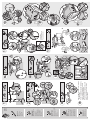
• Flip over frame assembly so the casters are
on a flat surface.
a
b
c
d
a
Hardware
11 mm (7/16 in.)
Wrench - 1
1/2 Inch Stainless
Steel Hex Bolts
(1/4 x 20 x 1/2 In.) - 10
1 Inch Zinc Screw
(1/4 x 20 x 1 In.) - 4
1/2 Inch Black Zinc
Hex Bolts
(1/4 x 20 x 1/2 In.) - 10
Nylon Washer - 10
• To adjust door:
Ob
• Retournez l’ensemble du châssis de sorte
que les roues reposent sur une surface
plane et à niveau.
Matériel
Clé de 11 mm
(7/16 po.) - 1
Ecrous hexagonaux
en acier inoxydable
de 1/2 pouce
(1/4 x 20 x 1/2 po.) - 10
Vis en zinc
de 1 pouce
(1/4 x 20 x 1 po) - 4
Ecrous hexagonaux en
zinc noir de 1/2 pouce
(1/4 x 20 x 1/2 po.) - 10
Rondelle en nylon - 10
• Pour ajuster la porte:
• Voltee el ensamble del bastidor de manera
que las ruedas locas queden sobre una
superficie plana y horizontal.
Herrajes
Llave de 11 mm
(7/16 pulg.) - 1
Acero inoxidable
1/2 pulgada
Pernos hexagonales
(1/4 x 20 x 1/2 pulg.) - 10
Tornillo de cinc de 1 pulgada
(1/4 x 20 x 1 pulg.) - 4
Cinc negro 1/2 pulgada
Pernos hexagonales
(1/4 x 20 x 1/2 pulg.) - 10
Arandela de nilón - 10
• Para ajustar la puerta:

1.
3.
2.
a
d
c
2 -4 -
4 -
4
4 -
3C
a
a
b
b
e
e
7
2 -
1
g
f
g
h
12
14
9
a)
b)
15
2 -
k
j
e
1 -
h
i
8
4 -
2 -
i
E/S-310/320
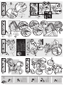
Hardware
Plastic Plug - 2
1 Inch Black Zinc
Hex Bolts
(1/4 x 20 x 1 In.) - 2
Black Zinc Hex Nut - 1
Door Handle
Hardware - 4
Before installing component,
remove protective film from the
stainless steel part.
#8 - 32 Machine
Screw - 4
Matériel
Bouchon en plastique - 2
Ecrous hexagonaux en
zinc noir de 1 pouce
(1/4 x 20 x 1 po.) - 2
Ecrou à tête hexagonale
en zinc noir - 1
Poignée De Porte - 4
Avant d’installer le composant,
retirez la pellicule protectrice de la
pièce en acier inoxydable.
Vis de mécanique de
#8 - 32 - 4
Herrajes
Tapón plástico - 2
Cinc negro 1 pulgada
Pernos hexagonales
(1/4 x 20 x 1 pulg.) - 2
Tuerca hexagonal
negra de cinc - 1
Componentes De La
Empuñadura De La Puerta - 4
Antes de instalar el componente,
retire la película protectora de la
pieza de acero inoxidable.
Tornillo de máquina
#8 - 32 - 4

19
20
2 -
21
4 -
320
17
3 -
22
m
j
l
k
l
m
n
16
18
S-310/320
1.
C
A
U
T
ION:
T
U
RN
T
HE G
AS OFF
A
T
TH
E
G
AS
S
U
PPLY
,
B
EFO
RE
ST
AR
TIN
G
.
1.
Loosen
Scr
ew
s.
1.
2.
4.
5.
3.
b.
1
O
F
F
A
R
R
E
T
E
/
A
P
A
G
A
D
O
1
O
F
F
A
R
R
E
T
E
/
A
P
A
G
A
D
O
6.
a.
50451 12/01/06
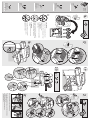
CAUTION: TURN THE GAS OFF AT THE
GAS SUPPLY, BEFORE STARTING.
KNOB BEZEL
ADJUSTMENT INSTRUCTIONS
TOOLS
NEEDED:
1. Loosen Screws.
2. Make sure bezel moves freely
in all directions.
3. Match end of alignment tool with valve stem by looking down barrel of tool (a).
Push alignment tool onto valve stem (b).
While holding control knob bezel, gently push alignment tool down.
Tool must freely return to up position.
4. Once aligned, continue to
hold control knob bezel
and tighten screws. Push
tool again to check for
free movement.
5. Remove alignment tool.
6. Install knob onto valve stem
and test for free movement.
Readjust if necessary.
AlignmentTool Phillips Screwdriver
Knob Bezel
C
A
U
T
IO
G
AS
S
U
PP
Hardware
Screw - 5
Clevis Pin - 2
Cotter Pin - 2
J-Clip - 7
IMPORTANT:
Knob bezels must be adjusted at this point.
See sheet in control knob packaging for bezel
adjustment instructions.
• Refer to Owner’s Manual for clip installation warning.
Aluminium Washer - 6
O
IMPORTANT:
La collerette du bouton doit être ajustée
à ce stade.
Voir la fiche fournie avec le bouton de
commande pour les instructions de
réglage de la collerette.
• Veuillez consulter le Manuel du Propriétaire pour
l’installation de la pince.
Matériel
Vis - 5
Axe - 2
Goupille fendue - 2
Pince en J - 7
Rondelle en aluminium - 6
• Refiérase al Manual del Propietario para la advertencia referente a la
instalación de la presilla.
IMPORTANTE:
Las molduras decorativas de la perilla deben
ajustarse ahora.
Refiérase a la hoja dentro del empaque de la
perilla de control para las instrucciones sobre
como ajustar las molduras decorativas.
Herrajes
Tornillo - 5
Pasador de horquilla - 2
Clavija hendida - 2
Grapa J - 7
Arandela de aluminio - 6
-
 1
1
-
 2
2
-
 3
3
-
 4
4


Weber 310 Manuel utilisateur
- Catégorie
- Cuisinières
- Taper
- Manuel utilisateur
- Ce manuel convient également à
dans d''autres langues
- English: Weber 310 User manual
- español: Weber 310 Manual de usuario
Documents connexes
-
Weber 89468 Manuel utilisateur
-
-
-
-
-
Weber GENESIS 320 Manuel utilisateur
-
-
-
-