
PO Box 100 • Hildebran, NC 28637 USA • 828-397-4200 Voice • 828-397-4415 Fax
https://www.elkproducts.com • email: info@elkproducts.com
APPLICATION:
The ELK-130 is an exceptionally loud, industrial grade siren driver
utilizes an intense sweeping yelp sound. With its wide operating
voltage range, loudness, and the capability of powering from one
source while being triggered from another, the ELK-130 is like
no other loud siren. This unique driver is ideal for security, early
warning, crowd protection, and many other applications.
High Powered Siren Driver
FEATURES:
• Extremely Powerful - Over 500 Watt Output
• Intensely Loud, Attention Getting Sound
• 2 Sounds - Yelp or Steady
• Heavy duty terminals for power input and speaker output to
accomodate larger wire gauges
• Includes fused, dual connection battery wires (ELK-W120) to allow
connection of back-up battery to control and driver power terminals
• Lifetime Limited Warranty
SPECIFICATIONS:
• Output: 130 db @ 1 meter, 24VDC
• Trigger Voltage: 9-24 VDC
• Operating Voltage: 12-24 Volts DC
• Speaker Load: Rated down to 1 Ohm
• Size: 5.13” x 4” x 1.06”
• RoHS Compliant
ELK-130
Features or Specications subject to change without notice.
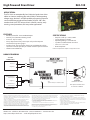
SwitchedPositive(+)
AlarmOutput1
SwitchedPositive(+)
AlarmOutput2
Negative(‐)
CONTROLPANEL
+YELP
+STEADY
‐NEG
Positive(+)
Negative(‐)
12‐24VDC
POWERSUPPLY
+PWR
‐PWR
SPEAKER
SPEAKER(S)
RatedDownto1Ohm
Eachspeakershouldberated
atminimumof20Watts
StatusLED
HOOKUP DIAGRAM
This device complies with part 15 of the FCC Rules. Operation is subject to the
following two conditions: (1) This device may not cause harmful interference, and
(2) this device must accept any interference received, including interference that
may cause undesired operation.
Changes or modifications not expressly approved by the party responsible for
compliance could void the user's authority to operate the equipment.
This equipment has been tested and found to comply with the limits for a Class
B digital device, pursuant to Part 15 of the FCC Rules. These limits are designed
to provide reasonable protection against harmful interference in a residential
installation. This equipment generates uses and can radiate radio frequency
energy and, if not installed and used in accordance with the instructions, may
cause harmful interference to radio communications. However, there is no guar-
antee that interference will not occur in a particular installation. If this equipment
does cause harmful interference to radio or television reception, which can be
determined by turning the equipment o and on, the user is encouraged to try to
correct the interference by one of the following measures:
• Reorient or relocate the receiving antenna.
• Increase the separation between the equipment and receiver.
• Connect the equipment into an outlet on a circuit dierent from that to which
the receiver is connected.
• Consult the dealer or an experienced radio/TV technician for help.
This device contains licence-exempt transmitter(s)/receiver(s) that comply
with Innovation, Science and Economic Development Canada’s licence-exempt
RSS(s). Operation is subject to the following two conditions:
• This device may not cause interference.
• This device must accept any interference, including interference that may
cause undesired operation of the device
L’émetteur/récepteur exempt de licence contenu dans le présent appareil est
conforme aux CNR d’Innovation, Sciences et Développement économique Cana-
da applicables aux appareils radio exempts de licence. L’exploitation est autorisée
aux deux conditions suivantes :
• L’appareil ne doit pas produire de brouillage;
• L’appareil doit accepter tout brouillage radioélectrique subi, même si le brouil-
lage est susceptible d’en compromettre le fonctionnement.
CAN ICES-3 (B)/NMB-3(B)
FCC AND IC COMPLIANCE STATEMENT:

1. BEFORE MAKING ANY CONNECTIONS ensure the control panel and power supply are powered down.
2. Connect the SPEAKER terminals to 1 or more alarm type speakers (see diagrams for multiple speaker hookup examples). Speaker
output is rated down ot 1 Ohm. The current draw of the driver varies based on the speaker load and operating voltage. DO NOT
EXCEED the output ratings of the control or power source. The chart below shows the estimated current draw based on speaker
load and operating voltage.
3. Connect the Yelp and/or Steady inputs to positive (+) switched alarm outputs on the control. Then connect the NEG input to the
negative of the control or power source. OBSERVE POLARITY!
NOTE: Should both inputs become triggered at the same time the Steady willl take priority and override the Yelp.
4. Connect the positive (+) of a 12-24 VDC power source to the PWR+ terminal. Connect the negative (-) of the power source to the PWR-
terminal. OBSERVE POLARITY!
INSTALLATION INSTRUCTIONS
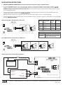
Voltage Total Speaker
Load
Current
Draw
Wattage
12 VDC 8 Ohms 1.5 Amps 18
12 VDC 4 Ohms 3.0 Amps 36
12VDC 2 Ohms 6.0 Amps 72
12VDC 1 Ohm 12 Amps 144
SwitchedPositive(+)
AlarmOutput1
SwitchedPositive(+)
AlarmOutput2
Negative(‐)
CONTROLPANEL
+YELP
+STEADY
‐NEG
BackupBattery
Positive(+)
BackupBattery
Negative(‐)
BACK‐UPBATTERY
‐
+
‐PWR
+PWR
30AmpFuse
ELK‐W120FusedDual
ConnectionBatteryWires
8 OHM
SPEAKER
8 OHM
SPEAKER
Each speaker should be rated at minimum of 20 Watts
Two 8 Ohm Speakers - Parallel wired = 4 Ohm load.
PO Box 100 • Hildebran, NC 28637 USA • 828-397-4200 Voice • 828-397-4415 Fax • https://www.elkproducts.com • email: [email protected]
Powering ELK-130 from Control Back-up Battery
8 OHM
SPEAKER
8 OHM
SPEAKER
8 OHM
SPEAKER
8 OHM
SPEAKER
Each speaker should be rated at minimum of 20 Watts
Four 8 Ohm Speakers - Parallel wired = 2 Ohm load.
L708 3/7/23
Status LED
Slow Blink Normal operation
Rapid Blink Power trouble (over current, over
voltage, or under voltage)
-
 1
1
-
 2
2


dans d''autres langues
- English: ELK ELK-130 Operating instructions
Autres documents
-
 Code 3 Emergency Systems 2021 Mode d'emploi
-
Uniden UM525BK Le manuel du propriétaire
-
Harris XL-185M Guide d'installation
-
Crown CTs 600 Manuel utilisateur
-
 Rockford Fosgate Punch Power 500.2 Manuel utilisateur
-
 Rockford Fosgate 250X2 Installation & Operation Manual
-
 Rockford Fosgate 75.2 Manuel utilisateur
-
 Rockford Fosgate Punch 100.2 Operations & Installation Manual
-
QSC GX Series Manuel utilisateur
-
Bosch Appliances 4000 Manuel utilisateur


