
INSTALLATION INSTRUCTIONS SHEET 1 OF 2
SAVE THESE INSTRUCTIONS
93130899 Rev. E
WARNING!
Fixtures must be grounded and installed in accordance with the National Electrical Code and all local codes. Failure to do so may increase
the
RISK OF PERSONAL INJURY, PROPERTY DAMAGE, FIRE AND DEATH.
Install and use so fixture failures do not cause a hazard and use only in
environments for which the product is specifically marked.
WARNING!
This product contains chemicals known to the State of California to cause cancer, birth defects, and/or other reproductive harm. Thoroughly
wash hands after installing, handling, cleaning, or otherwise touching this product.
WARNING!
Dangerous voltage exist within the unit and all precautions usually observed in handling high voltage equipment should be observed when
replacing light engine or otherwise servicing luminares. Disregarding this warning could result in electrical shock and possible injury to the individual
installing or servicing this equipment. Installation and servicing should be done by qualified personnel.
CAUTION!
Follow ALL luminaire recommendations, product markings, instructions, restrictions and warnings regarding luminaire operation and burning
position. Luminaire label shows electrical and environmental requirements and restrictions.
NOTE!
This luminare is designed for outdoor lighting applications with ambient temperatures not exceeding 40°C (104°F).
All electrical work must be done by a qualified electrician.
Turn off electric power to all affected circuits and allow to cool before installation or servicing.
A regularly scheduled maintenance program should be established to retain optimum light output and reduce heat retention. Dusting with a soft, clean,
dry cloth is normally sufficient for the optical system. Any accumulation of dust or dirt should be removed regularly.
Carefully read these instructions before installing product. If you do not understand these instructions, before starting any work, contact yourdistributor or
lightingtechsupport@currentlighting.com or (864) 678-1000
Give instructions to facility owner/manager for future reference.
READ THOROUGHLY BEFORE INSTALLATION
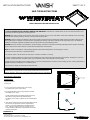
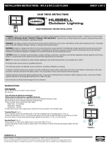
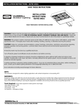
FIGURE 1
Direct Mount to Canopy Panel:
Tools Required:
Power Drill/Driver
5/16" Hex Drive Bit
2" Hole Saw
1. Cut a 2" hole for the luminaire boss in the canopy.
An existing hole up to 4" may be used.
2. Secure the luminaire to the canopy using the provided
self-drilling screws. (Fig 1)
Or drill mounting holes in the pattern shown and secure
the luminaire using customer-provided fasteners.
The fixture can be used as a pattern for the mounting holes.
(Fig. 2)
3. Insert electrical leads from the luminaire through the silicone
seal and into an appropriate customer-supplied" NPT
conduit. Screw the conduit into the threaded luminaire
boss. Seal the conduit connections as required. The
conduit should be attached to an appropriate junction box
for wiring connections.
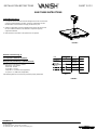
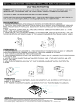
FIGURE 2
14.13 in
14.13 in
O
2in to 4in
HOLE
Current Lighting.
701 Millennium Blvd., Greenville, SC 29607
Tel: 864-678-1000 Website: www.currentlighting.com
MOUNTING SCREW
LOCATIONS
NOTE!
If this fixture is being installed in a 2-step process (the first being installation of
the fixture into the canopy and the second being the electrification of the fixture by an
electrical contractor), apply a layer of silicone 0.25 inches thick to the neck of the fixture.

SAVE THESE INSTRUCTIONS
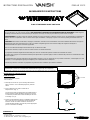
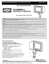
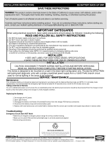
FIGURE 3
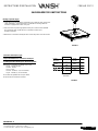
FIGURE 4
Electrical Connections (Fig. 4):
Turn off power to electrical connections.
Wiring must be performed by a qualified electrician.
Make the wiring connections as follows:
Black Wire - Line Voltage
White Wire - Neutral
Green Wire - Ground
Purple Wire - (V+) DIM Lead (if applicable)
Grey Wire - (V-) DIM Lead (if applicable)
If the dimming leads are not used, they should be properly terminated.
Pendant Mounting (Fig. 3):
1. Feed electrical leads from the luminaire through the silicone seal and into a
customer-supplied 3/4" NPT conduit. Screw the conduit firmly into the
threaded boss on the luminaire and apply sealant to the joint.
2. Attach an appropriate customer-supplied junction box to the other end of
the 3/4" conduit and attach to the structure as required to properly
support the luminaire.
3. Make electrical connections in the junction box as required.
BLACK
WHITE
GREEN
PURPLE
GREY
LINE
NEUTRAL
GROUND
DIM (+)
DIM (-)
LUMINAIRE
JUNCTION
BOX
93130899 Rev. E
Current Lighting.
701 Millennium Blvd., Greenville, SC 29607
Tel: 864-678-1000 Website: www.currentlighting.com
INSTALLATION INSTRUCTIONS SHEET 2 OF 2

AVERTISSEMENT!
Les appareils d'éclairages doivent être mis à la terre et installés selon le Code canadien de l'électricité et tous les codes locaux. Ne
pas se conformer à ces codes pourrait conduire à
DES SECOUSSES ÉLECTRIQUES ET UN DANGER DE MORT OU D'INCENDIE
. Installez l'appareil
d'éclairage seulement dans les environnements pour lesquels il est marqué, et de façon qu'un défaut ne puisse devenir un danger.
AVERTISSEMENT!
Ce produit contient des produits chimiques reconnus par l'état de la Californie causer le cancer, des malformations congénitales et
d'autres sévices à la reproduction. Bien se laver les mains après l'installation, le nettoyage ou après avoir touché le produit (particulièrement s'il est
brisé).
ATTENTION!
Suivre toutes les indications, marquages, instructions, restrictions et recommandations concernant l'utilisation du luminaire ainsi que les
dégagements requis et les précautions pour ne pas vous brûler. L'étiquette apposée sur le luminaire indique les exigences électriques et
environnementales ainsi que les restrictions applicables.
Tous les raccordements électriques doivent être faits par un électricien certifié.
Avant de faire l'entretien, coupez la source de courant et laissez se refroidir le luminaire.
Un programme d'entretien régulier devrait être établi pour conserver la luminosité optimale et réduire l'accumulation de chaleur.
Un chiffon doux et propre est normalement suffisant pour dépoussiérer le système optique. Toute accumulation de poussière ou saleté doit être retirée
de façon régulière.
Lire attentivement les présentes instructions avant d'installer le produit. Si vous ne comprenez pas les présentes instructions, communiquez avec votre
distributeur, ou avec lightingtechsupp[email protected] ou (864) 678-1000 au téléphone
Remettre les présentes instructions au propriétaire ou gestionnaire des installations pour référence ultérieure.
À LIRE ATTENTIVEMENT AVANT D'INSTALLER
SAUVEGARDEZ CES INSTRUCTIONS
93130899 Rev. E
FIGURE 1
Montage direct sur le panneau d'auvent:
Outils nécessaires:
Perceuse électrique
Embout hexagonal de 5/16in.
Scie cloche 2in.
1. Découpez un trou de 2in. pour le bossage du luminaire
dans la verrière. Un trou existant jusqu'à 4in. peut être
utilisé.
2. Fixez le luminaire à la verrière à l'aide du vis
autoperceuses. (Fig. 1.)
Ou percez des trous de montage dans le modèle illustré et
fixez le luminaire à l'aide de fixations fournies par le client.
Le luminaire peut être utilisé comme modèle pour les trous
le montage. (Fig. 2)
3. Insérez les fils électriques dans les conduit NPT 3/4in. fourni
par le client et visser le conduit dans le bossage fileté du
luminaire. Sceller le conduit connexions au besoin. Le
conduit doit être attaché à une boîte de jonction appropriée
pour les connexions de câblage.
FIGURE 2
14.13 in
14.13 in
O
2in to 4in
HOLE
MOUNTING SCREW
LOCATIONS
Current Lighting.
701 Millennium Blvd., Greenville, SC 29607
Tel: 864-678-1000 Website: www.currentlighting.com
INSTRUCTIONS D'INSTALLATION FEUILLE 1 OF 2
Si ce luminaire est installé dans un processus en 2 étapes (la première étant l'installation de
l'appareil dans la verrière et la seconde étant l'électrification de l'appareil par un entrepreneur
en électricité), appliquez une couche de silicone de 0,25 pouce d'épaisseur sur le col du luminaire.

INSTRUCTIONS D'INSTALLATION FEUILLE 2 OF 2
SAUVEGARDEZ CES INSTRUCTIONS
Montage suspendu (Fig.3):
1. Faites passer les fils électriques du luminaire par un câble de 3/4in. fourni par le
client conduit NPT. Vissez fermement le conduit dans le bossage fileté du
luminaire et appliquez du mastic sur le joint.
2. Fixez une boîte de jonction appropriée fournie par le client à l'autre extrémité
du le conduit de 3/4in. et attachez-le à la structure au besoin pour
soutenir le luminaire.
3. Effectuez les connexions électriques dans la boîte de jonction selon les besoins.
Connexions électriques (Fig.4):
Coupez l'alimentation des connexions électriques.
Le câblage doit être effectué par un électricien qualifié.
Effectuez les connexions de câblage comme suit:
Fil noir - Tension de ligne
Fil blanc - Neutre
Fil vert - Terre
Fil violet - Fil DIM (V +) (le cas échéant)
Fil gris - Fil DIM (V-) (le cas échéant)
Si les câbles de gradation ne sont pas utilisés,
ils doivent être correctement raccordés.
Boîte de
Dérivation
FIGURE 3
FIGURE 4
NOIR
BLANC
VERT
VIOLET
GRIS
LIGNE
NEUTRE
TERRE
DIM (+)
DIM (-)
Luminaire
93130899 Rev. E
Current Lighting.
701 Millennium Blvd., Greenville, SC 29607
Tel: 864-678-1000 Website: www.currentlighting.com
-
 1
1
-
 2
2
-
 3
3
-
 4
4


dans d''autres langues
- English: Whiteway VANISH Installation guide
Autres documents
-
Hubbell RWL1 Ratio Wall LED Light Guide d'installation
-
 Security Lighting Sling SG1 and SG2 Guide d'installation
-
 Security Lighting RFL4/RFL5 Guide d'installation
-
 Security Lighting RFL2/RFL3 Guide d'installation
-
 Security Lighting LNC2 Stock 12L and 18L Guide d'installation
-
 Security Lighting Ratio Area/Site Guide d'installation
-
 Security Lighting SG Sling Guide d'installation
-
Progress Lighting P250068-31M-WB Mode d'emploi
-
Progress Lighting 93133616 C Mode d'emploi
-
 Security Lighting Sling Battery Backup Guide d'installation


