GoldenEar ForceField 30 Le manuel du propriétaire
- Taper
- Le manuel du propriétaire

Owner’s Manual
Powered Subwoofers
ForceField
ForceFieldManual_ENG_FRENCH_01_14_22.indd 1ForceFieldManual_ENG_FRENCH_01_14_22.indd 1 1/19/22 10:23 AM1/19/22 10:23 AM

Congratulations!
Congratulations and thank you for purchasing GoldenEar’s™ ForceField Subwoofer! You are about
to hear the spectacular difference these technically advanced low frequency reproducers will
make in your music and/or home theater system!
Our engineering team’s years of audio products design experience in developing leading-edge
speaker systems has led to these extraordinary products. In order to ensure that you experience
maximum performance, please take a moment to fully read this owner’s manual and familiarize
yourself with the unique installation and set-up procedures for your new ForceField Subwoofer.
Please visit our website at www.GoldenEar.com for more information on the technology behind
your new speaker system. If you have additional questions, contact your Authorized GoldenEar™
Dealer or visit the Q&A page in the Tech Support section of our website.
Safety Precautions
READ THIS SECTION CAREFULLY BEFORE PROCEEDING!
WARNING: TO REDUCE THE RISK OF ELECTRIC SHOCK, DO NOT REMOVE COVER (OR BACK). NO USER-SERVICEABLE
PARTS INSIDE. REFER SERVICING TO QUALIFIED SERVICE PERSONNEL.
WARNING: TO REDUCE THE RISK OF FIRE OR ELECTRIC SHOCK, DO NOT EXPOSE THIS APPARATUS TO RAIN OR MOISTURE,
AND OBJECTS FILLED WITH LIQUIDS, SUCH AS VASES, SHOULD NOT BE PLACED ON THIS APPARATUS.
CAUTION: TO PREVENT ELECTRIC SHOCK, MATCH WIDE BLADE OF PLUG TO WIDE SLOT, FULLY INSERT.
CAUTION: FOR CONTINUED PROTECTION AGAINST RISK OF FIRE, REPLACE THE FUSE ONLY WITH THE SAME AMPERAGE
AND VOLTAGE TYPE. REFER REPLACEMENT TO QUALIFIED SERVICE PERSONNEL
WARNING: UNIT MAY BECOME HOT. ALWAYS PROVIDE ADEQUATE VENTILATION TO ALLOW FOR COOLING. DO NOT
PLACE NEAR A HEAT SOURCE, OR IN SPACES THAT CAN RESTRICT VENTILATION.
RECYCLING AND REUSE GUIDELINES FOR EUROPE
In accordance with the European Union WEEE (Waste Electrical and Electronic Equipment) directive effective
August 13, 2005, we would like to notify you that this product may contain regulated materials which, upon disposal,
according to the WEEE directive, require special reuse and recycling processing. For this reason GoldenEar
(manufacturers of GoldenEar speakers) has arranged with our distributors in European Union member nations to
collect and recycle this product at no cost to you. To fi nd your local distributor please contact the dealer from
whom you purchased this product or go to our website at www.goldenear.com.
Please note that the product only falls under the WEEE directive. When disposing of packaging and other shipping material we
encourage you to recycle through the normal channels.
2
ForceField Owner’s Manual
GoldenEar ForceField Manual
ForceFieldManual_ENG_FRENCH_01_14_22.indd 2ForceFieldManual_ENG_FRENCH_01_14_22.indd 2 1/19/22 10:23 AM1/19/22 10:23 AM

Important Safety Instructions
1. Read Instructions – All the safety and operating instructions should be read before the product is operated.
2. Retain Instructions – The safety and operating instructions should be retained for future reference.
3. Heed Warnings – All warnings on the product and in the operating instructions should be adhered to.
4. Follow Instructions – All operating and use instructions should be followed.
5. Cleaning – Unplug this product from the wall outlet before cleaning. Do not use liquid cleaners or aerosol cleaners. Use a damp,
soft cloth for cleaning base.
6. Water and Moisture – Do not use this product near water—for example, near a bath tub, wash bowl, kitchen sink, or laundry tub;
in a wet basement; or near a swimming pool; and the like.
7. Accessories – Do not place this product on an unstable cart, stand, tripod, bracket or table. The product may fall, causing serious
injury to a child or adult and serious damage to the product. Use only with a cart, stand, tripod, bracket or table recommended
by the manufaturer, or sold with the product. Any mounting of the product should follow manufacturer’s instructions and should
use a mounting accessory recommended by the manufacturer.
8. Ventilation – Slots and openings in the cabinet are provided for ventilation and to ensure reliable operation of the product and
to protect it from overheating, and these openings must not be blocked or covered. The openings should never be blocked by
placing the product on a bed, sofa, rug, or other similar surface. This product should not be placed in a built-in installation such
as a bookcase or rack unless proper ventilation is provided or the manufacturer’s instructions have been adhered to.
9. Power Sources – This product should be operated only from the type of power source indicated on the marking label. If you are
not sure of the type of power supply to your home, consult your product dealer or local power company. For products intended
to operate from battery power, or other sources, refer to the operating instructions.
10. Grounding and Polarization – This product may be equipped with a polarized alternating-current line plug (a plug having one
bladewiderthantheother).Thisplugwilltintothepoweroutletonlyoneway.Thisisasafetyfeature.Ifyouareunabletoinsert
theplugfullyintotheoutlet,tryreversingtheplug.Iftheplugshouldstillfailtot,contactyourelectriciantoreplaceyourobsolete
outlet. Do not defeat the safety purpose of the polarized plug.
11. Power-Cord Protection – Power supply cords should be routed so that they are not likely to be walked on or pinched by items
placed upon or against them, paying particular attention to cords at plugs, convenience receptacles, and the point where they
exit from the product.
12. Lightning – For added protection for this product during a lightning storm, or when it is left unattended and unused for long
periods of time, unplug it from the wall outlet. This will prevent damage to the product due to lightning and powerline surges.
13. Overloading –Donotoverloadwalloutlets,extensioncords,orintegralconveniencereceptaclesasthiscanresultinariskofre
or electric shock.
14. Object and Liquid Entry – Never push objects of any kind into this product through openings as they may touch dangerous
voltagepointsorshort-outpartsthatcouldresultinareorelectricshock.Donotexposethisapparatustodrippingorsplashing,
andensurethatnoobjectslledwithwater,suchasvases,areplacedontheapparatus.
15. Servicing – Do not attempt to service this product yourself as opening or removing covers may expose you to dangerous voltage
orotherhazards.Referallservicingtoqualiedservicepersonnel.
16. Damage Requiring Service – Unplugthisproductfromwalloutletandreferservicingtoqualiedpersonnelunderthe
following conditions:
a. When power supply cord or plug is damaged;
b. If liquid has been spilled, or objects have fallen into product;
c. If the product has been exposed to rain or water;
d. If the product does not operate normally by following the operating instructions.
Adjust only those controls that are covered by the operating instructions as an improper
adjustment of other controls may result in damage and will require extensive work
byaqualiedtechniciantorestoretheproducttoitsnormaloperation;
e. If the product has been dropped or damaged in any way;
f. If the product exhibits a distinct change in performance.
17. Replacement Parts –Whenreplacementpartsarerequired,besurethetechnicianhasusedreplacementpartsspeciedbythe
manufacturerorhavethesamecharacteristicsastheoriginalpart.Unauthorizedsubstitutionsmayresultinre,electricshock,or
other hazards
18. Safety Check – Upon completion of any service or repairs to this product, ask the service technician to perform safety checks to
determine that the product is in proper operating condition.
19. Wall or Ceiling Mounting – The product should be mounted to a wall or ceiling only as recommended by the manufacturer.
20. Heat – The product should be situated away from heat sources such as radiators, heat registers, stoves, or other products
(includingampliers)thatproduceheat.
3
GoldenEar ForceField Manual
ForceFieldManual_ENG_FRENCH_01_14_22.indd 3ForceFieldManual_ENG_FRENCH_01_14_22.indd 3 1/19/22 10:23 AM1/19/22 10:23 AM

SAFETY PRECAUTIONS SPECIFIC TO FORCEFIELD SUBWOOFER
The cautionary marking label is located on back of subwoofer.
POWER SUPPLY
1. The fuse and power disconnect device are located on the back of the subwoofer.
2. The disconnect device is the power cord, detachable at either the speaker or the wall.
3. The power cord must be disconnected from the subwoofer before servicing.
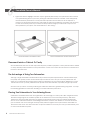
Unpacking Your ForceField Subwoofer
Please Inspect for Shipping Damage
Each Subwoofer leaves our plant in perfect condition. Any visible or concealed damage most likely occurred
in handling after it left our plant and should be reported at once to your GoldenEar Dealer and/or the delivery
company that delivered your Subwoofer. Please unpack your system carefully.
Save all cartons and packing materials in case you move or need to ship your system. Record the serial number
found on the back of the ForceField Subwoofer here:
_________________________________________________________________________
(Serial Number)
Please go to http://www.goldenear.com/support/registrationandwarranty and use the serial number(s) above to
complete your warranty registration.
4
ForceField Owner’s Manual
GoldenEar ForceField Manual
ForceFieldManual_ENG_FRENCH_01_14_22.indd 4ForceFieldManual_ENG_FRENCH_01_14_22.indd 4 1/19/22 10:23 AM1/19/22 10:23 AM

Subwoofer Installation
Your new ForceField subwoofer contains a built-in amplier and electronic crossover. Of the several ways to
install your subwoofer, none is considered “better” than another; rather, each is best depending on what type
of entertainment system you own and how you plan to integrate your subwoofer. Read these installation
suggestions below to determine which options best suit your needs. Please take care to perform all wiring
procedures with your system completely off.
Power Requirements
The ‘Watts’ (W) rating indicated on the rear panel of your GoldenEar ForceField subwoofer is the maximum a/c
power the subwoofer will draw when producing its maximum power output. However, the actual wattage draw
will vary with the bass content of the program material and is typically MUCH less (below 100 watts in normal
audio playback use).
Subwoofer Placement
Bass is less and less directional as it goes down in frequency, so your subwoofer can be located almost anywhere
in your listening room. (Your GoldenEar subwoofer has been designed to operate at frequencies generally below
150 Hz.) For best sonic integration, locating your subwoofer between your front speakers or beside one of them
and close to the front wall will usually provide the best bass performance. If this location is not possible your
subwoofer may be placed anywhere in the room without affecting the image and soundstage of your stereo
or multichannel speaker system. (See additional notes below about installing your subwoofer in a cabinet.)
Here are some principles to keep in mind when deciding on your subwoofer’s placement:
1. For maximum output, the subwoofer should be placed close to a wall. Corner placement will increase
the subwoofer’s output, but may exaggerate room nodes (peaks in frequency) causing
muddy, ill-dened bass performance in the room.
2. While one GoldenEar subwoofer will always sound great, the use of two subwoofers will denitely
enhance your system’s performance by providing a smoother and more consistent room response.
With two subs, it is recommended that you locate the subwoofers out of the corners on the same side
of the room as the main speaker of the same channel -or- one in the front of the room and one in the
rear of the listening room.
3. Always remember that frequency response and output level are greatly inuenced by the subwoofer’s
placement. A movement of even a foot or two can dramatically change your room’s bass response
characteristics. We recommend you experiment with placement in your particular listening room in order
to achieve the highest performance from your ForceField subwoofer.
5
GoldenEar ForceField Manual
ForceFieldManual_ENG_FRENCH_01_14_22.indd 5ForceFieldManual_ENG_FRENCH_01_14_22.indd 5 1/19/22 10:23 AM1/19/22 10:23 AM

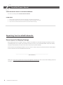
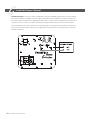
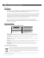
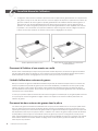
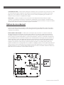
4. Figures A & B below highlight how bass output is generally affected by room placement. When seated
in a typical listening area of your room, placing the subwoofer inside the “shaded” areas will typically
result in best bass performance. Corner placement provides the most bass, but at the expense of
accuracy. A subwoofer placed near a wall usually provides a good balance of quantity and accuracy.
Controls on the back panel of your subwoofer are provided to align your subwoofer’s output to the
other speakers in your system, see section below on “Fine Tuning.”
Placement Inside a Cabinet Or Cavity
The ForceField subs, because of their unique low-frequency radiation properties, can be placed inside a cabinet
or cavity and still provide excellent in-room performance. Just be sure to leave at least 2 inches of clearance on
the front of the subwoofer.
The Advantage of Using Two Subwoofers
Although a single GoldenEar ForceField subwoofer provides exceptional performance and substantial output,
the quality and quantity of bass can be further improved with the use of two (or even four) subwoofers. This
allows you to randomize the standing waves within your listening room so that bass will be distributed in a more
uniform manner. Two (or more) subwoofers also provide even lower distortion, especially at high output levels.
The extra care you take in correctly positioning the subwoofer will result in greater listening enjoyment. So, keep
the following guidelines in mind when deciding on the best subwoofer placement:
Placing Two Subwoofers in Your Listening Room
GoldenEar’s ForceField subwoofers are engineered to be used singly or in stereo pairs. With a single subwoofer,
both left and right signals are combined (either at the subwoofer or at the receiver/processor). With stereo
subwoofers, the left and right low frequency signals can be reproduced by their own individual subwoofers.
The use of one subwoofer achieves outstanding performance; however, the addition of a second subwoofer
(one for the left and one for the right channel) clearly offers the highest level of performance achievable for
both movies and music. Two subwoofers also couple much better to the air in your room (four times better) and
of course offer double the power.
6
Corner Placement Should Be Avoided Place in Shaded Areas for Best Performance
AB
ForceField Owner’s Manual
GoldenEar ForceField Manual
ForceFieldManual_ENG_FRENCH_01_14_22.indd 6ForceFieldManual_ENG_FRENCH_01_14_22.indd 6 1/19/22 10:23 AM1/19/22 10:23 AM

In addition to the above mentioned setup for stereo subwoofers, some state-of-the-art home theater installations
have begun to use a separate subwoofer placed in the rear of the room and we recommend this for the
absolute ultimate in movie bass performance. When using two subwoofers, placing one in the front of the room
and the other in the rear of the room usually provides the best bass performance and sonic integration. If those
locations are not possible or if you want to experiment with placement options using two subwoofers, the
following procedure will be a helpful guide to achieving better bass performance. “Refer to Subwoofer
Connection” section below, then proceed as follows:
1. Temporarilyturnallspeakersoff(eitherbyturningyouramplieroffordisconnectingthem).
2. Connect and place one subwoofer in the central area of your listening room (follow directions for
connection,asoutlinedinthefollowingsection).
3. At a moderately loud level, play music or a video soundtrack with extended bass that is repetitive
or continuous.
4. Walk around your room and note where the bass sounds louder and where it sounds quieter.
5. Placetherstsubwooferwithinalouderbassareaofyourroom;thenplacethesecondsubwooferwithin
a quieter bass area of your room.
6. Connectbothsubwoofersandswitchallspeakersbackon;andswitchtheamplieron,orreconnectit.
7. Now follow “Fine Tuning” instructions after the Subwoofer Connection section to optimize your system’s
overall bass performance.
NOTE: Theprecedingisonlyaguideline.YoumaywanttouseabasstestdiscandSPL(SoundPressureLevel)
meter to more accurately determine the bass characteristics of your listening room (see dealer for more
information).Rememberthatroomacousticsvary,soitmaytakesomeexperimentingwithplacementto
achieve best performance.
7
Powering Up the Subwoofer
Your ForceField subwoofer contains a built-in, active powered subwoofer section as well as an electronic
crossover. Each ForceField subwoofer must be plugged into an electrical socket (use an unswitched outlet if
possible)oftheappropriatevoltage(asindicatedonthebackofyourunit)usingtheplugontheendofthe
black cord attached to the electronics module on the back of the subwoofer. The ForceField subwoofer has
a special circuit which automatically turns the powered subwoofer section on when a signal is fed to the loud-
speakeranddoesnotrequireanon/offswitch.(WhentheSubwooferisrstpluggedin,theLEDwillashfor
30 seconds while the sub conducts a self-test, initializing the software and hardware. After 30 sec, if there is no
audiosignal,theLEDwillturnoffandthesubwooferwillgointostandbymodedrawingalowamountofpower
whilewaitingforanaudiosignal.)
TheLEDonthebackpanelwilllightupwhenasignalissensedandtheamplierwillturnon.Afteryoustop
listening,itmaytakeuptoanhourfortheampliertoactuallyturnoff.(Please note: In some instances, because
of RF presence in your area, the LEDs may not turn off. However, this is nothing to be concerned about as the
ampliers draw almost no power when they are idling.) Please note: It is normal to hear a slight pop from the
subwoofer when the amp powers up.
NOTE: To prevent accidental damage to your subwoofer from overdriving the system, the subwoofer features an
internal overload protection circuit, which will turn the subwoofer off or down when overdriven or overheated
and will then resume normal operation after a few minutes.
GoldenEar ForceField Manual
ForceFieldManual_ENG_FRENCH_01_14_22.indd 7ForceFieldManual_ENG_FRENCH_01_14_22.indd 7 1/19/22 10:23 AM1/19/22 10:23 AM

Subwoofer Connection
We recommend the use of high-quality cables and connectors when hooking up your subwoofer
(see your dealer).
INPUT CONFIGURATIONS
Left/LFE Input (Line-Level RCA) – Allows connection from the Sub/LFE Output of an A/V receiver, processor or
other suitable low-passed, low-level source.
Left and Right Inputs (Line-Level RCA) – Allows connection from the Left/Right preamp outputs of your receiver
or processor, or integrated amplier, for use in a stereo (rather than home theater) system.
CONTROLS
Your GoldenEar ForceField Series Subwoofer is equipped with operating controls on the back panel to ensure
excellent exibility and maximum performance in any installation. Most of them are the “set and forget” type,
although you may occasionally nd certain controls require minor adjustments.
Subwoofer Level – This is a volume control, use it to balance the subwoofer output level to best blend with your
other speakers. For suggestions on setting the Subwoofer Controls once your subwoofer has been connected
refer to the section on “Fine Tuning” on page 12.
Lowpass Crossover – Controls the subwoofer’s upper-frequency cut-off. This control (low-pass lter) is continuously
variable between 40 and 150 Hz. This low pass lter control is used to obtain the optimum transition between the
subwoofer and your main speakers when the subwoofer is connected using the Left/Right Inputs and the input
switch is selected for Left/Right input use (see diagram below).
NOTE: The ForceField’s Lowpass Crossover (low-pass lter) is bypassed altogether when the Left/LFE Input is used and
the Input Switch is set to the down position (LFE in). The Sub Out/LFE Out of A/V receivers, processors or subwoofer
control units have their own low-pass lter built into the circuit as part of their bass management setup.
We receive many questions from subwoofer owners asking us where to set the Lowpass Crossover in a variety of
different setups. Although many people think that there is a specic frequency at which to set the controls in their
system, this can only be determined by you. Experimentation is recommended (due to system placement and sub-
jective variables) to obtain the best sound for you. See the “Fine Tuning” section on page 12 for some suggestions.
8
ForceField Owner’s Manual
GoldenEar ForceField Manual
ForceFieldManual_ENG_FRENCH_01_14_22.indd 8ForceFieldManual_ENG_FRENCH_01_14_22.indd 8 1/19/22 10:23 AM1/19/22 10:23 AM

Input Switch – Down position (LFE IN) for use with an A/V receiver, processor or subwoofer control unit
that has a Sub-Out/LFE-Out jack, or up position (Left/Right In) when used in a stereo conguration with
the Left/Right preamp outputs of an A/V receiver, processor or integrated amplier.
Auto On/Off – Your subwoofer will turn on when it receives an input signal — eliminating the need for a
power switch. If no signal is sensed for a period of time, the subwoofer will automatically switch off. See
“Powering Up the Subwoofer” section below for more details.
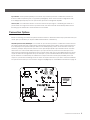
Connection Options
Before connecting your subwoofer, please read this section to determine which setup option best suits your
needs. (See your dealer if you require additional information or assistance.)
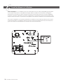
Left/LFE Input From Sub/LFE Output – For use with an A/V receiver, processor or subwoofer control unit that
has a Sub-Out/LFE-Out jack. Using an RCA-to-RCA analog interconnect cable, connect the subwoofer to
the Left/LFE Input and position the Input Switch in the LFE IN (Down) position, as shown below. Most A/V
receivers, preamps and processors feature a mono (line-level) Sub/LFE output intended to be used with
subwoofers. You can feed this Sub/LFE output of your A/V receiver or processor to the LFE input on the
subwoofer and achieve full performance. These outputs have their own low-pass lter built into the circuit
as part of their bass management setup. The LFE input on your ForceField subwoofer are direct coupled
inputs which are not affected by the subwoofer’s Lowpass Crossover control (low-pass lter). If the sub
output on your receiver is full range, does not have a low-pass crossover, or you wish to use the ForceField’s
low-pass crossover then you must connect using the Left/Right Inputs, as described in the section on page 10.
9
GoldenEar ForceField Manual
ForceFieldManual_ENG_FRENCH_01_14_22.indd 9ForceFieldManual_ENG_FRENCH_01_14_22.indd 9 1/19/22 10:23 AM1/19/22 10:23 AM

10
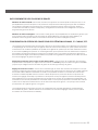
Left and Right Inputs – For use in a stereo conguration using the Left/Right preamp outputs of your receiver,
processor or integrated amplier. Use RCA-to-RCA analog interconnect cables to connect the subwoofer
and position the Input Switch in the LEFT/RIGHT IN (Up) position, as shown. In this conguration the subwoofer’s
Lowpass Crossover control is now active, allowing a setting that matches the roll of your main speakers.
In this conguration your main speakers will run full range with no low frequency roll-off. The ForceField Low-
pass Crossover control will then allow you to augment the bass extension of your system beyond the main
speakers’ limitations.
ForceField Owner’s Manual
GoldenEar ForceField Manual
ForceFieldManual_ENG_FRENCH_01_14_22.indd 10ForceFieldManual_ENG_FRENCH_01_14_22.indd 10 1/19/22 10:23 AM1/19/22 10:23 AM

11
DUAL SUBWOOFER CONNECTIONS
Connection using Left/LFE Inputs – From your A/V receiver or preamp, attach a RCA-type “Y” connector to the
Sub/LFE out (unless your receiver or processor has two Sub outs) and then run an RCA-type analog interconnect
cable to each subwoofer’s LEFT/LFE Input. Select the LFE In (DOWN) position on the Input Select switch. For further
setup instructions, refer to Bass Management System Setup section below.
Connection using Left/Right Inputs – Connect the Left preamp output to the Left RCA input of the rst sub and the
Right preamp output to the Right RCA input on the second sub. Select the Left/Right In (UP) position of the Input
Switch.
BASS MANAGEMENT SETUP FOR MULTI-CHANNEL, 5.1-CHANNEL, ETC., SYSTEMS
Multi-channel surround sound systems have a critical speaker setup and channel balancing procedure for
setting the level for all speakers and how bass is directed which must be followed if the system is to perform
properly. Many problems relating to the overall sound of the system can be clearly traced back to improper
system balance. Also note that multi-channel surround sound systems have bass management systems which
vary from unit to unit. This bass management system must be properly adjusted. Many problems relating to the
overall sound of the system can be traced back to improper bass management settings.
Bass Management Settings when using LFE Input: On your A/V receiver or processor’s Speaker Setup Menu, set all
speakers to “Small*” and set Subwoofer to “Yes” to direct all bass and LFE information to the Sub(s).
Setting Channel Levels: Using your receiver or A/V processor’s Speaker Level Calibration Menu, set each speaker
(channel) in the system to the same volume level. While you can get reasonable results doing this by ear, it is best
to use an inexpensive Sound Pressure (SPL) meter to get better channel to channel balance. Some new receivers
and processors have Auto Set Up functions that use a supplied microphone to set levels automatically. Also note
that bass level should be set to individual taste, not just to a given reading on the SPL meter. Also note that most
inexpensive SPL meters suffer signicant roll-off when measuring bass frequencies, making it even more important
to “adjust bass to taste.”
(*Small and Large settings on speaker setup menus determine the routing of bass information, see your dealer for
more assistance on the correct settings for your specic speaker system and environment.)
GoldenEar ForceField Manual
ForceFieldManual_ENG_FRENCH_01_14_22.indd 11ForceFieldManual_ENG_FRENCH_01_14_22.indd 11 1/19/22 10:23 AM1/19/22 10:23 AM

12
FINE TUNING
Once you have the rest of your speakers positioned in the room (and have set speaker distances and calibrated
speaker levels with your Processor or A/V Receiver, if applicable) it’s time for a little ne tuning.
(NOTE: Set tone or equalizer controls on your receiver or preamplier to at (or 0°) and switch any loudness
controls off.)
When setting up your subwoofer use music and video soundtracks that you know well. They should contain
selections with extended bass that is continuous and repetitive. When you are adjusting your subwoofer,
remember that bass should not be overbearing — the subwoofer should not draw attention to itself — but
the overall system sound shouldn’t be “thin” or difcult to hear.
The following procedure is only for setups utilizing the Left/Right Inputs on the ForceField subwoofer, and are sim-
ply a suggested method to achieve the best results. (If using the Left/LFE input with an A/V receiver or processor
that is controlling the crossover and level settings, ignore this section).
1. Turn the Subwoofer Level control completely counter-clockwise to its minimum;
2. Turn the Subwoofer Cut-Off Frequency control to its highest frequency (i.e. 150 Hz);
3. While you listen to a music or movie selection in your primary listening area, have an assistant turn up the
Subwoofer Level control until the subwoofer can be clearly heard;
4. Turn the Subwoofer Level control completely counter-clockwise to its minimum;
5. Turn the Subwoofer Cut-Off Frequency control completely counterclockwise(i.e. 40 Hz);
6. Slowly rotate the Subwoofer Level control until you match the subwoofer output level with the level
of your front speakers. Bass should be clearly audible, but not intrusive;
7. Slowly rotate the Subwoofer Cut-Off Frequency control until you hear the best subwoofer/main speaker
blend. If the sound is too “thin,” you have not set the frequency high enough; if the sound becomes
“boomy” you have set the frequency too high. Adjust until you nd the most natural balance.
Complete Home Theater Systems
We strongly suggest that you use a matching GoldenEar Left, Right, Center channel and Rear/Surround speakers
to complete your GoldenEar home theater system.
ForceField Owner’s Manual
GoldenEar ForceField Manual
ForceFieldManual_ENG_FRENCH_01_14_22.indd 12ForceFieldManual_ENG_FRENCH_01_14_22.indd 12 1/19/22 10:23 AM1/19/22 10:23 AM

13
Troubleshooting
If you experience any difculties with your ForceField subwoofers, try the suggestions described below. If you are
still having problems, please consult your GoldenEar Authorized Dealer for assistance.
1. Make sure all your system interconnects and power cords are solidly in place.
2. Should you experience any level of ground hum or noise, try plugging the power cord into the same
circuit as your amplier.
3. The system is provided with sophisticated internal protection circuitry. If for some reason the protection
circuitry is tripped, please turn down your system’s volume and wait ve minutes before trying the system
again. If the amplier should overheat, the system will turn off until the amplier cools down and resets.
4. Check to be sure that your power cord has not been damaged.
5. Check that no foreign objects or liquid has entered the subwoofer.
6. Check the fuse on the back panel (replace only with the exact matching value fuse)
7. If you cannot get the subwoofer to turn on or if no sound comes out and you are sure the system is set
up properly, please bring the Subwoofer to your GoldenEar Authorized Dealer for assistance.
But make sure you call rst.
Service
Service and warranty work on your GoldenEar Subwoofers will normally be performed by your local GoldenEar
dealer. If, however, you wish to return the speaker to us, please contact us rst, describing the problem and
requesting authorization as well as the location of the nearest factory service center. Please note that the address
given in this booklet is the address of our ofce. Under no circumstances should Subwoofers be shipped to our
ofces or returned without contacting us rst and obtaining return authorization.
The Quest Group dba
GoldenEar™
2621 White Road
Irvine, CA 92614 USA
Phone: 949-800-1800
Technical assistance
It is our pleasure to offer assistance if you have any questions regarding your ForceField subwoofer or its set-up.
Please contact your nearest GoldenEar dealer or contact us directly at 949-800-1800.
GoldenEar ForceField Manual
ForceFieldManual_ENG_FRENCH_01_14_22.indd 13ForceFieldManual_ENG_FRENCH_01_14_22.indd 13 1/19/22 10:23 AM1/19/22 10:23 AM

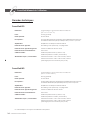
Specications
ForceField30
Dimensions: 1211⁄16" (32.2 cm) H (w/feet) x 113⁄8" (28.9 cm) W x 1531⁄32" (40.6 cm) D
Weight: 31.50 lbs. (14.29 kg)
FrequencyResponse: 18 Hz – 250 Hz
DriverComplement: One 8" long-throw high-output bass driver
One 9" x 11" quadratic planar infrasonic radiator
Amplier: 1000WattForceFielddigitalamplier
LFELine-LevelInput: Unltered(nolowpass),direct-coupled
Right/LeftLine-LevelInput: Variable Low-Pass from 40 Hz - 150 Hz
NorthAmericanVoltageInput: 120V 60 Hz
FuseSize: 5-amp 250-volt slow blow fuse (110-volt version)
3.15-amp 250-volt slow blow fuse (240-volt version)
PowerRequirements/Consumption: Low Voltage Version - 120 V at 50 or 60 Hz / 1400 Watts
High Voltage Version - 240 V at 50 or 60 Hz / 1400 Watts
(Approved for NA (TUV) and the CE market.)
ForceField40
Dimensions: 1411⁄16" (37.3 cm) H (w/feet) x 139⁄32" (33.7 cm) W x 185⁄16" (46.5 cm) D
Weight: 40.50 lbs. (18.37 kg)
FrequencyResponse: 14 Hz – 250 Hz
DriverComplement: One 10" long-throw high-output bass driver
One 11" x 13" quadratic planar infrasonic radiator
Amplier: 1200WattForceFielddigitalamplier
LFELine-LevelInput: Unltered(nolowpass),direct-coupled
Right/LeftLine-LevelInput: Variable Low-Pass from 40 Hz - 150 Hz
NorthAmericanVoltageInput: 120V 60 Hz
FuseSize: 5-amp 250-volt slow blow fuse (110-volt version)
3.15-amp 250-volt slow blow fuse (240-volt version)
PowerRequirements/Consumption: Low Voltage Version - 120 V at 50 or 60 Hz / 1400 Watts
High Voltage Version - 240 V at 50 or 60 Hz / 1400 Watts
(Approved for NA (TUV) and the CE market.)
Specicationsaresubjecttochangewithoutnotice.
14
ForceFieldOwner’sManual
GoldenEar ForceField Manual
ForceFieldManual_ENG_FRENCH_01_14_22.indd 14ForceFieldManual_ENG_FRENCH_01_14_22.indd 14 1/19/22 10:23 AM1/19/22 10:23 AM

15
GoldenEar ForceField Manual
ForceFieldManual_ENG_FRENCH_01_14_22.indd 15ForceFieldManual_ENG_FRENCH_01_14_22.indd 15 1/19/22 10:23 AM1/19/22 10:23 AM

Limited Warranty
5-YEARS FOR DRIVERS AND CABINETS,
3-YEARS FOR ELECTRONIC COMPONENTS
GoldenEar™ warrants to the original retail purchaser only that this GoldenEar Loudspeaker Product (the “Product”) will be free
from defects in materials and workmanship for a period of ve (5) years covering the drivers and cabinets, and three (3) years for
the electronic components from the date of the original purchase from a GoldenEar Authorized Dealer. However, this warranty will
automatically terminate prior to the expiration of ve (5) years for the drivers and cabinets and three (3) years for the electronic
components if the original retail purchaser sells or otherwise transfers the Product to any other party. The original retail purchaser
shall hereinafter be referred to as “you.” Defective Products must be shipped, together with proof of date of purchase, prepaid
insured to the Authorized Dealer from whom you purchased the Product, or to the nearest factory service center. Product(s) must
be shipped in the original shipping container or its equivalent; in any case the risk of loss or damage in transit is to be borne by
you. If, upon examination at the Factory or a GoldenEar Authorized Dealer, it is determined that the unit was defective in materials
or workmanship at any time during this Warranty period, GoldenEar or the GoldenEar Authorized Dealer will, at its option, repair or
replace this Product at no additional charge, except as set forth below. All replaced parts and Product(s) become the property
of GoldenEar. Product(s) replaced or repaired under this Warranty will be returned to you, within a reasonable time, freight collect.
This Warranty does not include service or parts to repair damage caused by accident, misuse, abuse, negligence, inadequate
packing or shipping procedures, commercial use, voltage in excess of the rated maximum of the unit, cosmetic appearance
of cabinetry not directly attributable to defects in materials or workmanship, or service, or repair or modication of the Product
which has not been authorized by GoldenEar. GoldenEar makes no Warranty with respect to its Products purchased from dealers
or outlets other than GoldenEar Authorized Dealers. This Warranty is in lieu of all other expressed Warranties. If this Product is
defective in material or workmanship as warranted above, your sole remedy shall be repair or replacement as provided above.
In no event will GoldenEar be liable to you for any incidental or consequential damages arising out of the use or inability to use
the Product, even if GoldenEar or a GoldenEar Authorized Dealer has been advised of the possibility of such damages, or for any
claim by any other party. Some states do not allow the exclusion or limitation of consequential damages, so the above limitation
may not apply to you.
All implied warranties on the Product are limited to the duration of this expressed Warranty. Some states do not allow limitation
on how long an implied Warranty lasts, so the above limitations may not apply to you. This Warranty gives you specic legal rights,
and you also may have other rights which vary from state to state.
Visit us at www.goldenear.com
Copyright © 2022 GoldenEar. All rights reserved.
Reproduction in whole or in part without our express permission is prohibited.
This product complies with the essential requirements of the EMC directive 89/336/EEC
GoldenEar ForceField Manual PART #: 3268AG00 01142022
ForceFieldManual_ENG_FRENCH_01_14_22.indd 16ForceFieldManual_ENG_FRENCH_01_14_22.indd 16 1/19/22 10:23 AM1/19/22 10:23 AM

This product complies with the essential requirements of the EMC directive 89/336/EEC
GoldenEar ForceField Manual PART #: 3268AG00 01142022
Manuel de l’utilisateur
Caissons de graves ampliés
ForceField
ForceFieldManual_ENG_FRENCH_01_14_22.indd 17ForceFieldManual_ENG_FRENCH_01_14_22.indd 17 1/19/22 10:23 AM1/19/22 10:23 AM

Félicitations !
Félicitations et merci d’avoir acheté un caisson de graves ForceField de GoldenEar™ ! Vous êtes
sur le point de constater une différence spectaculaire sur votre système hi-fi ou home cinéma
avec cette enceinte basse fréquence techniquement évoluées !
Ces produits extraordinaires sont le fruit des années d’expérience dans la conception de produits
audio acquises par nos ingénieurs lors du développement de systèmes d’enceintes acoustiques
de pointe. Pour assurer des performances maximales, veuillez prendre un moment pour lire
complètement le manuel de l’utilisateur et vous familiariser avec les instructions d’installation et
de confi guration de votre nouveau caisson de graves ForceField.
Pour plus d’informations sur la technologie sur laquelle repose votre nouveau système
d’enceintes, visitez notre site web à www.GoldenEar.com. Pour toute autre question,
adressez-vous à votre revendeur GoldenEar™ autorisé ou visitez la page FAQ dans la section
Support de notre site web.
Mesures de précaution
LIRE CETTE SECTION AVEC ATTENTION AVANT DE POURSUIVRE !
AVERTISSEMENT : POUR RÉDUIRE LE RISQUE DE CHOC ÉLECTRIQUE, NE PAS RETIRER LE CAPOT (OU PANNEAU ARRIÈRE). NE
CONTIENT AUCUNE PIÈCE RÉPARABLE PAR L’UTILISATEUR. CONFIER LES RÉPARATIONS À DU PERSONNEL D’ENTRETIEN QUALIFIÉ.
AVERTISSEMENT : POUR RÉDUIRE LE RISQUE D’INCENDIE OU DE CHOC ÉLECTRIQUE, NE PAS EXPOSER CET APPAREIL À LA PLUIE
OU À L’HUMIDITÉ ET NE PAS PLACER D’OBJETS REMPLIS DE LIQUIDE, TELS QUE DES VASES, SUR L’APPAREIL.
ATTENTION : POUR ÉVITER TOUT CHOC ÉLECTRIQUE, BRANCHER LA FICHE SUIVANT LA BONNE POLARITÉ, LE CAS ÉCHÉANT, ET
L’ENFONCER COMPLÈTEMENT.
ATTENTION : POUR PRÉSERVER LA PROTECTION CONTRE LES RISQUES D’INCENDIE, REMPLACER LE FUSIBLE UNIQUEMENT PAR UN
MODÈLE DE MÊME TENSION ET INTENSITÉ. CONFIER LE REMPLACEMENT À DU PERSONNEL D’ENTRETIEN QUALIFIÉ.
AVERTISSEMENT : L’APPAREIL PEUT DEVENIR CHAUD. TOUJOURS PRÉVOIR UNE AÉRATION SUFFISANTE POUR PERMETTRE LE
REFROIDISSEMENT. NE PAS PLACER À PROXIMITÉ D’UNE SOURCE DE CHALEUR OU DANS DES ESPACES SUSCEPTIBLES DE
RESTREINDRE L’AÉRATION.
RECYCLAGE ET RÉUTILISATION EN EUROPE
En conformité avec la directive européenne DEEE (Déchets d’équipements électriques et électroniques) en vigueur
depuis le 13 août 2005, nous tenons à vous informer que ce produit peut contenir des matières réglementées dont
l’élimination, en vertu de la directive DEEE, suppose un traitement spécial favorisant leur recyclage et leur revalo-
risation. À cette fi n, GoldenEar (le fabricant des enceintes GoldenEar) prend en charge par l’intermédiaire de ses
distributeurs dans les pays membres de l’Union européenne la collecte et le recyclage de ce produit sans aucun frais
pour vous. Pour connaître le distributeur local, adressez-vous au revendeur chez qui vous avez acheté ce produit ou
visitez notre site web à www.goldenear.com.
Veuillez noter que seul ce produit est couvert par la directive DEEE. Nous vous encourageons à recycler l’emballage et autres matériaux
d’expédition par les moyens habituels.
2GoldenEar Manuel ForceField
ForceField Manuel de l’utilisateur
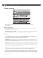
AVERTISSEMENT
RISQUE DE CHOC ÉLECTRIQUE
NE PAS OUVRIR
AVERTISSEMENT : POUR RÉDUIRE LE RISQUE DE CHOC
ÉLECTRIQUE, NE PAS RETIRER LE CAPOT (OU PANNEAU
ARRIÈRE). NE CONTIENT AUCUNE PIÈCE RÉPARABLE
PAR L’UTILISATEUR. CONFIER LES RÉPARATIONS À DU
PERSONNEL D’ENTRETIEN QUALIFIÉ.
L’éclair à pointe de fl èche dans un triangle
équilatéral met en garde contre la présence d’un
« tension dangereuse » non isolée dans l’enceinte
du produit qui peut être d’une ampleur suffi sante
pour présenter un risque de choc électrique.
Le point d’exclamation dans un triangle
équilatéral informe les utilisateurs de l’existence
d’importantes instructions d’utilisation et
d’entretien (dépannage) dans la documentation
qui accompagne l’appareil.
ForceFieldManual_ENG_FRENCH_01_14_22.indd 18ForceFieldManual_ENG_FRENCH_01_14_22.indd 18 1/19/22 10:23 AM1/19/22 10:23 AM

Consignes de sécurité importantes
1. Lire les instructions – Toutes les instructions de sécurité et d’utilisation doivent être lues avant d’utiliser le produit.
2. Conserver les instructions – Les instructions de sécurité et d’utilisation doivent être conservés pour toute référence ultérieure.
3. Respecter les mises en garde – Toutes les mises en garde apposées sur le produit et dans les instructions d’utilisation doivent
être respectées.
4. Suivre les instructions – Toutes les instructions d’exploitation et d’utilisation doivent être suivies.
5. Nettoyage – Débrancher le produit de la prise murale avant de le nettoyer. Ne pas utiliser de produits nettoyants liquides ou en
aérosol. Utiliser un chiffon doux humide pour nettoyer la base.
6. Eau et humidité – Ne pas utiliser ce produit en présence d’eau, par exemple près d’une baignoire, d’un lavabo ou d’une évier,
dans un sous-sol humide ou à proximité d’une piscine, etc.
7. Accessoires – Ne pas placer ce produit sur un chariot, socle, trépied, console ou tablette qui n’est pas stable. Le produit peut
chuter, ce qui peut provoquer des blessures graves à un enfant ou un adulte et des dommages graves au produit. Utiliser
uniquement un chariot, socle, trépied, console ou tablette recommandé par le fabricant ou vendu avec le produit. Tout
montageduproduitdoitêtreconformeauxinstructionsdufabricantetdoitfaireappelàdesaccessoiresdexation
recommandés par le fabricant.
8. Aération – Lesfentesetouverturesdanslecaissonsontprévuesàdesnsd’aérationetpourassurerunfonctionnementable
du produit et l’empêcher de surchauffer. Ces ouvertures ne doivent pas être obstruées ni couvertes. Ces ouvertures ne doivent
jamais être obstruées par le placement du produit sur un lit, canapé, tapis ou autre surface semblable. Ce produit ne doit pas
êtreintégrédansunestructuretellequ’unebibliothèqueouuneétagèresaufsiuneaérationsufsanteestprévueouqueles
instructions du fabricant sont respectées.
9. Alimentation électrique – Ce produit doit être branché exclusivement sur le type d’alimentation électrique indiqué sur l’étiquette.
En cas de doute sur le type d’alimentation électrique du domicile, consulter le revendeur du produit ou la compagnie
d’électricité locale. Pour les produits conçus pour fonctionner sur batterie ou autres sources d’alimentation, se reporte aux
instructions d’utilisation.
10. Mise à la terre et polarisation – Cetappareilpeutêtreéquipéd’unechesecteurpolarisée(dontl’unedeslamesestpluslarge
quel’autre).Cettechenepeutsebrancherdanslaprisequedansunseulsens.C’estunmécanismedesécurité.Silechene
peutpasêtreinséréecomplètementdanslaprise,essayerdelatournerdansl’autresens.Silachenerentretoujourspas,
s’adresser à un électricien pour faire changer la prise obsolète. Ne pas tenter d’aller à l’encontre de l’objectif de protection
delachepolarisée.
11. Protection du cordon électrique – Le cordon d’alimentation électrique doit être acheminé de façon à éviter qu’on puisse
marcherdessusouqu’ilsoitécrasépardesobjetsplacésdessusoucontrelui,enaccordantuneattentionparticulièreàlache,
à la prise de courant et au point où le cordon sort de l’appareil.
12. Foudre – Pour assurer la protection de ce produit durant un orage ou s’il doit être laissé sans surveillance et inutilisé pendant une
durée prolongée, il est conseillé de le débrancher de la prise de courant. Cela évitera les dommages au produit en cas de
foudre et de surtension du courant secteur.
13. Surcharge – Ne pas surcharger les prises de courant, cordons de rallonge ou prises « confort » intégrées car cela peut présenter
un risque d’incendie ou de choc électrique.
14. Intrusion d’objets ou de liquide – Ne jamais introduire de quelconques objets à travers les ouvertures de l’appareil car ils
pourraient venir au contact de tensions dangereuses ou produire un court-circuit susceptible de provoquer un incendie ou
un choc électrique. Ne pas exposer cet appareil à des égouttements ou éclaboussures et ne jamais place un objet rempli d’eau,
tel qu’un vase, sur l’appareil.
15. Réparation – Ne jamais tenter de réparer ce produit soi-même car l’ouverture ou le démontage des capots peut exposer les
personnesàdestensionsdangereusesouautresdangers.Conertouteslesréparationsàdupersonneld’entretienqualié.
16. Dommages nécessitant réparation – Débranchezleproduitdelaprisedecourantetconersaréparationàdupersonnelqualié
dans les situations suivantes :
a.Silecordonoulached’alimentationélectriquesontendommagés;
b.Siduliquideaétérenverséoudesobjetssonttombésdansl’appareil;
c.Sil’appareilasubiunechuteoutoutautredommage;
d.Sil’appareilnefonctionnepasnormalementlorsqu’onsuitlesinstructionsd’utilisation.
Ajusteruniquementlesréglagesquisontdécritsdanslesinstructionsd’utilisationcarlamodicationinappropriée
d’autresréglagespeutendommagerl’appareiletnécessitersondépannageparuntechnicienqualiépourle
remettreenétatdemarche;
e.Sil’appareilasubiunechuteoutoutautredommage;
f.Sileproduitprésenteunealtérationnotabledesonfonctionnement.
17. Pièces de rechange – Sidespiècesderechangesontnécessaires,veilleràcequeleréparateurutilisedespiècesrecommandéespar
le fabricant ou présentant les mêmes caractéristiques que les pièces d’origine. Les pièces de rechange non autorisées peuvent
présenter un risque d’incendie, de choc électrique ou d’autres dangers.
18. Contrôles de sécurité – Suiteàtouteopérationd’entretienouderéparationsurceproduit,demanderauréparateurd’effectuerdes
contrôlesdesécuritépourvérierqueleproduitenbonétatdemarche.
19. Pose murale ou au plafond – La pose murale ou au plafond du produit devra impérativement respecter les recommandations du fabricant.
20. Chaleur – Le produit doit être placé à l’écart de sources de chaleur telles que des radiateurs, registres de chauffage, poêles ou
autresproduits(ycomprisdesamplicateurs)quidégagentdelachaleur.
3
GoldenEar Manuel ForceField
ForceFieldManual_ENG_FRENCH_01_14_22.indd 19ForceFieldManual_ENG_FRENCH_01_14_22.indd 19 1/19/22 10:23 AM1/19/22 10:23 AM

MESURES DE PRECAUTION PROPRES AU CAISSON DE GRAVES FORCEFIELD
L’ETIQUETTE DE MISE EN GARDE EST APPOSEE AU DOS DU CAISSON DE GRAVES.
ALIMENTATION ELECTRIQUE
1. Le fusible et le moyen de sectionnement électrique sont placés à l’arrière du caisson de graves.
2. Le moyen de sectionnement est le cordon d’alimentation, qui peut être débranché au niveau du caisson ou de la prise murale.
3. Le cordon d’alimentation doit être débranché du caisson de graves avant toute intervention.
Déballage du caisson de graves ForceField
Veiller à contrôler le produit à la réception
Chaque caisson de graves est expédié de notre usine en parfait état. Tout dommage visible ou dissimulé
éventuel se sera probablement produit lors de la manutention après le départ de l’usine et devra être signalé
sans délai au revendeur GoldenEar ou à la société de transport qui a livré le caisson de graves. Déballer le s
ystème avec précaution.
Conserver tous les cartons et matériaux d’emballage en cas de besoin futur pour un déménagement ou le ren-
voi du produit. Consigner le numéro de série gurant au dos du caisson de graves ForceField ici :
_________________________________________________________________________
(Numéro de série)
Aller à http://www.goldenear.com/support/registrationandwarranty et utiliser le(s) numéro(s) de série ci-dessus
pour l’enregistrement de la garantie.
4
GoldenEar Manuel ForceField
ForceField Manuel de l’utilisateur
ForceFieldManual_ENG_FRENCH_01_14_22.indd 20ForceFieldManual_ENG_FRENCH_01_14_22.indd 20 1/19/22 10:23 AM1/19/22 10:23 AM
La page est en cours de chargement...
La page est en cours de chargement...
La page est en cours de chargement...
La page est en cours de chargement...
La page est en cours de chargement...
La page est en cours de chargement...
La page est en cours de chargement...
La page est en cours de chargement...
La page est en cours de chargement...
La page est en cours de chargement...
La page est en cours de chargement...
La page est en cours de chargement...
-
 1
1
-
 2
2
-
 3
3
-
 4
4
-
 5
5
-
 6
6
-
 7
7
-
 8
8
-
 9
9
-
 10
10
-
 11
11
-
 12
12
-
 13
13
-
 14
14
-
 15
15
-
 16
16
-
 17
17
-
 18
18
-
 19
19
-
 20
20
-
 21
21
-
 22
22
-
 23
23
-
 24
24
-
 25
25
-
 26
26
-
 27
27
-
 28
28
-
 29
29
-
 30
30
-
 31
31
-
 32
32


GoldenEar ForceField 30 Le manuel du propriétaire
- Taper
- Le manuel du propriétaire
dans d''autres langues
Autres documents
-
JBL SUB80P Wireless Subwoofer Le manuel du propriétaire
-
Klipsch RW-8 Le manuel du propriétaire
-
 MartinLogan 210 Manuel utilisateur
-
Klipsch Reference series Manuel utilisateur
-
Boston Acoustics BT1100 Le manuel du propriétaire
-
Paradigm Defiance V12 Manuel utilisateur
-
Klipsch SW-350 Le manuel du propriétaire
-
Jamo C 912 SUB Subwoofer Manuel utilisateur
-
Klipsch R-12SW - Scratch & Dent Manuel utilisateur
-
Jamo C 912 SUB Manuel utilisateur
