Chief TILSC2HUU Guide d'installation
- Catégorie
- Supports de projecteur
- Taper
- Guide d'installation
Ce manuel convient également à

INSTALLATION INSTRUCTIONS
TILSC2HUU
TILSC3HUU
Unilumins U-Panel-S LED
Mount Side Covers Accessory
Spanish Product Description
German Product Description
Portuguese Product Description
Italian Product Description
Dutch Product Description
French Product Description
TILSC2HUU / TILSC3HUU

TILSC2HUU / TILSC3HUU Installation Instructions
2
DISCLAIMER
Legrand | AV and its affiliated corporations and subsidiaries
(collectively “Legrand | AV”), intend to make this manual
accurate and complete. However, Legrand | AV makes no claim
that the information contained herein covers all details,
conditions or variations, nor does it provide for every possible
contingency in connection with the installation or use of this
product. The information contained in this document is subject
to change without notice or obligation of any kind. Legrand | AV
makes no representation of warranty, expressed or implied,
regarding the information contained herein. Legrand | AV
assumes no responsibility for accuracy, completeness or
sufficiency of the information contained in this document.
Chief® is a registered trademark of Legrand AV Inc.
DEFINITIONS
MOUNTING SYSTEM: A MOUNTING SYSTEM is the
primary Chief product to which an accessory and/or component
is attached.
ACCESSORY: AN ACCESSORY is the secondary Chief
product which is attached to a primary Chief product, and may
have a component attached or setting on it.
COMPONENT: A COMPONENT is an audiovisual item
designed to be attached or resting on an accessory or mounting
system such as a video camera, CPU, screen, display,
projector, etc.
WARNING: A WARNING alerts you to the possibility of
serious injury or death if you do not follow the instructions.
CAUTION: A CAUTION alerts you to the possibility of
damage or destruction of equipment if you do not follow the
corresponding instructions.
IMPORTANT SAFETY INSTRUCTIONS
WARNING: Failure to read, thoroughly understand, and
follow all instructions can result in serious personal injury,
damage to equipment, or voiding of factory warranty! It is the
installer’s responsibility to make sure all accessories are
properly assembled and installed using the instructions
provided.
WARNING: Use this accessory only for its intended use as
described in these instructions. Do not use attachments not
recommended by the manufacturer.
WARNING: Never operate this accessory if it is damaged.
Return the accessory to a service center for examination and
repair.
WARNING: Do not use this accessory outdoors.
IMPORTANT ! :
The TILSC2HUU and TILSC3HUU
accessories
are designed to be mounted to the UU Series LED
Wall Mount.
--SAVE THESE INSTRUCTIONS--

Installation Instructions TILSC2HUU / TILSC3HUU
3
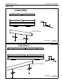
DIMENSIONS
27.00
685.8
3.00
76.2
0.75
19.1
SLOTS IN BRACKETS ALLOW
FOR SLIGHT DEPTH ADJUSTMENT
END USER ASSEMBLY
DIMENSIONS: INCHES
[MILLIMETERS]
TILSC2HUU
40.50
1028.7
3.00
76.2 0.75
19.1
SLOTS IN BRACKETS ALLOW
FOR SLIGHT DEPTH ADJUSTMENT
END USER ASSEMBLY
DIMENSIONS: INCHES
[MILLIMETERS]
TILSC3HUU

TILSC2HUU / TILSC3HUU Installation Instructions
4
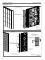
DIMENSIONS....cont’d
A
TILSC3HUU BRACKET
(2 INCLUDED WITH EACH KIT)
TILSC2HUU BRACKET
(2 INCLUDED WITH EACH KIT)
BRACKETS ATTACH TO MOUNT
WITH INCLUDED 1/4- 20 PHILLIPS
HEAD SCREWS
TIL1X2UU MOUNT
(SOLD SEPARATELY)
TIL1X3UU MOUNT
(SOLD SEPARATELY)
DETAIL A
SCALE 1 : 2
CONNECTOR BRACKET
TO KEEP COVER BRACKET ALIGNED
(2 INCLUDED IN EACH COVER KIT)
DIMENSIONS: INCHES
[MILLIMETERS]
DIMENSIONS: INCHES
[MILLIMETERS]
TIL1X2UU MOUNT
(SOLD SEPARATELY)
TILSC2HUU BRACKET
(2 INCLUDED IN EACH KIT)
BRACKET ATTACHES TO SIDE OF MOUNT
WITH 1/4-20 PHILLIPS HEAD SCREWS

Installation Instructions TILSC2HUU / TILSC3HUU
5
LEGEND
Tighten Fastener
Apretar elemento de fijación
Befestigungsteil festziehen
Apertar fixador
Serrare il fissaggio
Bevestiging vastdraaien
Serrez les fixations
Loosen Fastener
Aflojar elemento de fijación
Befestigungsteil lösen
Desapertar fixador
Allentare il fissaggio
Bevestiging losdraaien
Desserrez les fixations
Phillips Screwdriver
Destornillador Phillips
Kreuzschlitzschraubendreher
Chave de fendas Phillips
Cacciavite a stella
Kruiskopschroevendraaier
Tournevis à pointe cruciforme
Open-Ended Wrench
Llave de boca
Gabelschlüssel
Chave de bocas
Chiave a punte aperte
Steeksleutel
Clé à fourche
By Hand
A mano
Von Hand
Com a mão
A mano
Met de hand
À la main
Hex-Head Wrench
Llave de cabeza hexagonal
Sechskantschlüssel
Chave de cabeça sextavada
Chiave esagonale
Zeskantsleutel
Clé à tête hexagonale
Pencil Mark
Marcar con lápiz
Stiftmarkierung
Marcar com lápis
Segno a matita
Potloodmerkteken
Marquage au crayon
Drill Hole
Perforar
Bohrloch
Fazer furo
Praticare un foro
Gat boren
Percez un trou
Adjust
Ajustar
Einstellen
Ajustar
Regolare
Afstellen
Ajuster
Remove
Quitar
Entfernen
Remover
Rimuovere
Verwijderen
Retirez
Optional
Opcional
Optional
Opcional
Opzionale
Optie
En option
Security Wrench
Llave de seguridad
Sicherheitsschlüssel
Chave de segurança
Chiave di sicurezza
Veiligheidssleutel
Clé de sécurité

TILSC2HUU / TILSC3HUU Installation Instructions
6
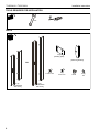
TOOLS REQUIRED FOR INSTALLATION
PARTS
#1, #2
7/16"
OR
A (2)
[TILSC2HUU
side cover]
A (2)
[TILSC3HUU
side cover]
B (2)
[Backing plate]
C (2)
[Mounting bracket]
D (4)
1/4-20 x 1/2" E (8)
4-40 x 1/4" F (4)
1/4-20 G (4)
1/4"

Installation Instructions TILSC2HUU / TILSC3HUU
7
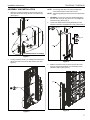
ASSEMBLY AND INSTALLATION
1. Attach two mounting brackets (C) to each side cover (A)
using two 1/4-20" hex nuts (F) and two 1/4" washers (G).
(See Figure 1)
Figure 1
2. Loosely install the 1/4-20 x 1/2" Phillips pan head screws
(D) for each side cover into the side of the mount. (See
Figure 2)
Figure 2
NOTE: The backing plate (B) is only used if multiple side
covers will be used on each side of mount.
NOTE: The backing plate (B) is NOT used on the topmost side
cover.
3. OPTIONAL: Connect one end of the backing plate (B) to
the lower side cover (A) using two 4-40 x 1/4" Phillips flat
head screws (E). (See Figure 3)
4. Loosen and adjust all the mounting brackets (C) to the
maximum extension, and tighten hex nut (F). (See Figure 3)
Figure 3
5. Slide the lower side cover (A) down onto the side of the
mount by hanging the brackets onto the Phillips screws
installed in Step 2. (See Figure 4)
Figure 4
1
(F) x 2
(G x 2)
(C x 2)
(A)
[TILSC2HUU shown as example]
2
(D) x 2
(B)
3
(E) x 2
(A)
4
(F) x 2
4
5
(A)

TILSC2HUU / TILSC3HUU Installation Instructions
8
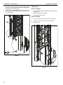
6. Slide the top side cover (A) down into place onto the lower
side cover, by hanging the brackets onto the Phillips screws
installed in Step 2. (See Figure 5)
7. Install two 4-40 x 1/4" Phillips flat head screws (E) into the
top of the backing plate (B) installed in the lower side cover
(A). (See Figure 5)
Figure 5
Adjustments
Side Cover Height
1. Loosen Phillips head screws (installed in Step 2) on mount.
(See Figure 6)
2. Move side cover to proper height.
3. Tighten Phillips head screws.
Side Cover Depth
4. Loosen hex nuts on the cover brackets. (See Figure 6)
5. Adjust side covers into the edge of the LED panels.
6. Tighten hex nuts.
Figure 6
7
(E) x 2
6
(A)
1
4

Installation Instructions TILSC2HUU / TILSC3HUU
9

TILSC2HUU / TILSC3HUU Installation Instructions
10

Installation Instructions TILSC2HUU / TILSC3HUU
11

TILSC2HUU / TILSC3HUU Installation Instructions
USA/International A 6436 City West Parkway, Eden Prairie, MN 55344
P800.582.6480 / 952.225.6000
F877.894.6918 / 952.894.6918
Europe A Franklinstraat 14, 6003 DK Weert, Netherlands
P+31 (0) 495 580 852
F+31 (0) 495 580 845
Asia Pacific A Office No. 918 on 9/F, Shatin Galleria
18-24 Shan Mei Street
Fotan, Shatin, Hong Kong
P852 2145 4099
F852 2145 4477
8800-003178 Rev00
2019 Legrand | AV
www.legrandav.com
10/19
-
 1
1
-
 2
2
-
 3
3
-
 4
4
-
 5
5
-
 6
6
-
 7
7
-
 8
8
-
 9
9
-
 10
10
-
 11
11
-
 12
12


Chief TILSC2HUU Guide d'installation
- Catégorie
- Supports de projecteur
- Taper
- Guide d'installation
- Ce manuel convient également à
dans d''autres langues
- English: Chief TILSC2HUU Installation guide
Documents connexes
-
Chief VCT Manuel utilisateur
-
Chief PACFCB Guide d'installation
-
-
-
-
-
-
-
Chief FCA515 Guide d'installation
-
Chief FCA4U Guide d'installation