Fisher & Paykel HP24ILTX2 Mode d'emploi
- Catégorie
- Hottes
- Taper
- Mode d'emploi
Ce manuel convient également à

INTEGRATED INSERT
VENTILATION HOOD
HP24ILTX2 and HP36ILTX2 models
HOTTE DE VENTILATION
ENCASTRABLE
Modéls HP24ILTX2 et HP36ILTX2
INSTALLATION GUIDE / USER GUIDE
GUIDE D’INSTALLATION / GUIDE D’UTILISATION
US CA

English Page 1 – 21
Français
Page 23 – 43

1
CONTENTS
Introduction 3
Safety and warnings 4
Installation instructions 7
Operating instructions 15
Cleaning and maintenance 16
Parts and accessories 18
Limited Warranty 19
Registration
To register your product visit our website: fisherpaykel.com/register
EN


3
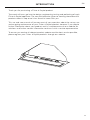
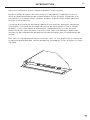
INTRODUCTION
Thank you for purchasing a Fisher & Paykel product.
Thousands of hours go into the design, engineering, testing and perfecting of each
Fisher & Paykel appliance. The care and attention given to creating these beautiful
products doesn’t stop once it has found its home with you.
This use and care manual will answer most of your questions about the set-up, use
and on-going maintenance of your Fisher & Paykel product; however if you require
further information about your product and its use please consult our website for
solutions and further contact information to discuss with a service representative.
To ensure you receive all relevant product updates and the best service possible,
please register your Fisher & Paykel products through our website.
EN

4
SAFETY AND WARNINGS
!WARNING!
Weight Hazard
The ventilation hood is heavy. Please ensure adequate care is taken
wheninstalling the ventilation hood to prevent personal injury.
The ventilation hood must be installed onto a solid wall, stud, beam
ortruss.
Product weight: 16lbs (7.1kg) HP24 / 20lbs (9.1kg) HP36.
!WARNING!
Electric Shock Hazard
Always disconnect the appliance from the mains power supply before
carrying out any maintenance or repairs.
Installation work and electrical wiring must be done by qualified
person(s) in accordance with all applicable codes and standards,
including fire-rated construction.
Failure to do so can result in death, electric shock, fire or injury to
persons.

5
SAFETY AND WARNINGS
IMPORTANT SAFETY INSTRUCTIONS
READ THE ENTIRE SET OF INSTRUCTIONS BEFORE INSTALLING OR USING
THIS APPLIANCE. Manuals can also be found on our website www.fisherpaykel.com.
CAUTION: For general ventilating use only. Do not use to exhaust hazardous
or explosive materials and vapors.
WARNING! To reduce the risk of fire, electric shock, or injury to persons, observe
thefollowing:
– Use this unit only in the manner intended by the manufacturer. If you have
questions, contact the manufacturer. For residential use only.
– Before servicing or cleaning unit, switch power off at service panel and lock
the service disconnecting means to prevent power from being switched on
accidentally. When the service disconnecting means cannot be locked, securely
fasten a prominent warning device, such as a tag, to the service panel.
– Installation work and electrical wiring must be done by qualified person(s)
in accordance with all applicable codes and standards, including fire-rated
construction.
– Sufficient air is needed for proper combustion and exhausting of gases through
the flue (chimney) of fuel burning equipment to prevent back drafting. Follow
the heating equipment manufacturer’s guideline and safety standards such as
those published by the National Fire Protection Association (NFPA), and the
American Society for Heating, Refrigeration and Air Conditioning Engineers
(ASHRAE), and the local code authorities.
– When cutting or drilling into wall or ceiling, do not damage electrical wiring
and other hidden utilities.
– Ducted fans must always be vented to the outdoors.
– This unit must be grounded.
CAUTION: To reduce risk of fire and to properly exhaust air, be sure to duct air
outside – Do not vent exhaust air into spaces within walls or ceilings or into attics,
crawl spaces, or garages.
WARNING: To reduce the risk of fire, use only metal ductwork.
WARNING: To reduce the risk of fire or electric shock, do not use this fan with
any solid-state speed control device.
WARNING: To reduce the risk of a range top grease fire:
– Never leave surface units unattended at high settings. Boilovers cause smoking
and greasy spillovers that may ignite. Heat oils slowly on low or medium
settings.
– Always turn hood ON when cooking at high heat or when flambéing food (ie
Crepes Suzette, Cherries Jubilee, Peppercorn Beef Flambé)
– Clean ventilating fans frequently. Grease should not be allowed to accumulate
on fan or filter.
– Use proper pan size. Always use cookware appropriate for the size of the
surface element.
EN

6
SAFETY AND WARNINGS
WARNING: To reduce the risk of injury to persons in the event of a range top
grease fire, observe the following*:
– SMOTHER FLAMES with a close-fitting lid, cookie sheet, or metal tray, then
turn off the burner. BE CAREFUL TO PREVENT BURNS. If the flames do not go
out immediately, EVACUATE AND CALL THE FIRE DEPARTMENT.
– NEVER PICK UP A FLAMING PAN – You may be burned.
– DO NOT USE WATER, including wet dishcloths or towels – a violent steam
explosion will result.
– Use an extinguisher ONLY if:
– You know you have a Class ABC extinguisher, and you already know
how to operate it.
– The fire is small and contained in the area where it started.
– The fire department is being called.
– You can fight the fire with your back to an exit.
WARNING: Unplug or disconnect the appliance from the power supply before
servicing or cleaning.
READ AND SAVE THESE INSTRUCTIONS
*Based on “Kitchen Firesafety Tips” published by NFPA.

7
IINSTRUCTIONS D’INSTALLATION
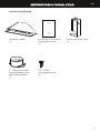
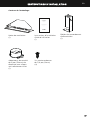
Contents of packaging
Installation instructions
User guide manual
(1)
Ventilation hood
(1)
3/8” (10mm)
Self tapping screw
(4)
Power connection box
(1)
6” (152mm) diameter
Ducting adapter with
back draft damper
(1)
US CA
INSTALLATION INSTRUCTIONS
USER GUIDE
INSTRUCTIONS D’INSTALLATION
GUIDE D’UTILISATION
HP24ILTX1 and HP36ILTX1 models
Modèles HP24ILTX1 et HP36ILTX1
Integrated Perimeter Insert Ventilation Hood
Hotte de Ventilation Périmétrique Encastrable
EN

8
INSTALLATION INSTRUCTIONS
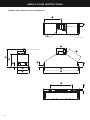
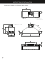
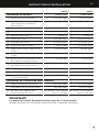
Product and cabinetry cutout dimensions
K
L
ØM
A
E
B
G
D
P
F
C
I
J
H
O
N
UL power
connection box
Ducting adapter

9
INSTALLATION INSTRUCTIONS
EN
HP24 HP36
PRODUCT DIMENSIONS inches (mm) inches (mm)
AOverall height of product 133/4” (350) 13 3/4” (350)
BOverall height of product (with
power connection box)
181/4” (463) 181/4” (463)
COverall width of product 207/8” (530) 3211/16” (830)
DOverall depth of product 11” (280) 11” (280)
EThickness of flange 1/16” (2) 1/16” (2)
FWidth of chassis 193/8” (492) 313/16” (792)
GDepth of chassis 101/16” (255) 101/16” (255)
HHeight of side of chassis 711/16” (195) 711/16” (195)
IWidth of top surface of chassis 113/4” (298) 113/4” (298)
JLength of angled surface of chassis 67/8” (175) 11” (280)
KDistance from center of ducting
outlet to back of chassis
31/8“ (80) 31/8” (80)
LDistance from center of ducting
outlet to side of chassis
95/8” (245) 159/16” (395)
MDiameter of ducting outlet 6” (152) 6” (152)
NDistance between center of lights 143/4” (375) 269/16” (675)
ODistance from center of light to
front of product
19/16” (40) 1 9/16” (40)
CABINETRY CUTOUT DIMENSIONS
Overall width of cutout 1911/16” (500) 311/2” (800)
Overall depth of cutout 101/4” (260) 101/4” (260)
PBase of brackets/clips to bottom of
chassis
min. 9/16” – max. 19/16”
(min. 15 – max. 40)
min. 9/16” – max. 19/16”
(min. 15 – max. 40)
IMPORTANT!
Actual product dimensions may vary by ± 1/16”(2mm).
Please read the entire instructions before installing the ventilation hood.

10
INSTALLATION INSTRUCTIONS
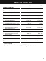
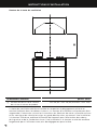
Height of ventilation hood
MINIMUM CLEARANCES inches (mm)
QHeight top of cooktop to base
of product
min. 26” – max. 30” (min 660 – max. 762)
This ventilation hood must be installed no lower than the minimum height indicated
in the table above. Minimum installation height may be greater if required by the
cooktop manufacturer or safety and warning section of this user guide. Installation
at the minimum height will improve the efficiency of capturing cooking odors, grease
and smoke. Installation at the maximum height improves user ergonomics by offering
increased head room.
Q

11
INSTALLATION INSTRUCTIONS
WARNING!
To reduce the risk of fire, use only metal ductwork. Do not use flexible plastic ducting
CAUTION!
To reduce risk of fire and to properly exhaust air, be sure to duct air outside – do not
vent exhaust air into spaces within walls or ceilings or into attics, crawl spaces, or
garages.
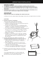
Venting options
Attention should be given to ensure that any applicable regulations concerning the
discharge of exhaust air are fulfilled.
The ventilation hood can be installed to operate with the exhaust air ducted
externally from the kitchen.
Ducted
For ducted installation it is recommended that 6” (152mm) diameter, rigid or semi-rigid
ducting is used. This will require a 65/16” (160mm) (min) round hole in the ceiling or
wall. Care should be taken to position the hole correctly.
For optimal efficiency use the shortest and straightest duct route possible and use rigid
or semi-rigid ducting for reduced noise and increased airflow. Flexible metal ducting
should only be used as a last resort (ie in difficult installations) and if used ensure that it
is straight and smooth and extended as much as possible.
EN

12
INSTALLATION INSTRUCTIONS
WARNING!
This appliance is heavy and requires two persons for unpacking and installation
Installation work and electrical wiring must be done by qualified person(s) in
accordance with all applicable codes and standards.
Failure to install the screws or fixing device in accordance with these instructions
mayresult in electrical hazards
IMPORTANT!
Wear gloves to protect against sharp edges.
The manufacturer is not liable for any damage caused by not following these instructions.
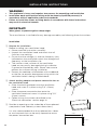
Installation
1 Prepare for installation.
Before installing your ventilation hood:
Please read the instructions carefully.
Unpack the ventilation hood and check that all
functions are working.
Ensure that the voltage (V) and the frequency (Hz)
indicated on the serial plate match the voltage and
frequency at the installation site.
The stainless steel surfaces of the ventilation
hood are very easily damaged during installation
if grazed or knocked by tools. Please take care to
protect the surfaces during installation.
Protect the cooktop surface below with cardboard,
or the like, to prevent damage occurring whilst the
ventilation hood is being installed above.
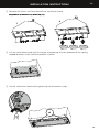
2 Attach ducting adapter and power connection box to
the ventilation hood
Place the ducting adapter onto the ventilation
hood and screw it in place using 3/8” (10mm)
screws.
Place the power connection box onto the
ventilation hood and screw it in place using 3/8”
(10mm) screws.
Follow wiring instructions described in the
‘Electrical connection’ section page14.
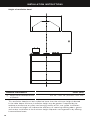
3 Provide an opening on the underside of the cupboard
(see product and cabinetry cutout dimensions).
It is also recommended that the cupboard has a door
or service panel that can be easily opened to access
the power connection box
width
depth

13
INSTALLATION INSTRUCTIONS
EN
1
2
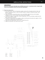
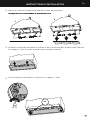
4 Remove the filters and face plate of the ventilation hood.
5 Lift the ventilation hood and fit through the opening of the cupboard till the spring
loaded brackets / clips hold the product in place.
x4
6 Secure ventilation hood while tightening the 4 brackets / clips.
Images are for representation only, models may vary.

14
INSTALLATION INSTRUCTIONS
WARNING!
Electrical wiring must be done by qualified person(s) in accordance with all applicable
codes and standards and the unit must be grounded.
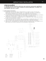
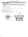
7 Electrical connection
Run three wires, two for the power supply and one for the ground wire, from the
power connection box on the ventilation hood to a power connection point near
the installation.
Open the power connection box on the ventilation hood and secure the power
conductor with a cULus listed strain relief (not included).
Connect the power conductors to the conductors for the ventilation hood, black to
black and white to white.
Connect the grounding wire (green or bare) to the ground conductor (green) of the
ventilation hood power connection box.
Secure all the connections with cULus listed wire nuts.
Replace the power connection box cover.
EN
Gray 4 speed
Black 3 speed
Red 2 speed
Blue 1 speed
Brown (neutral)

15
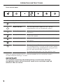
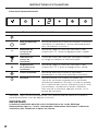
OPERATING INSTRUCTIONS
Touch control panel
CONTROL PANEL FEATURES
Light Turn the lights on or off.
Power ON/OFF Turn the ventilation hood on or off. The fan
automatically turns on to operate at level 1.
Reduce fan speed Adjust the fan speed levels from 1 – 3 with 1 being
the lowest.
Fan speed indicator The fan speed level icon illuminates red with the
current fan speed.
Increase fan speed Adjust the fan speed levels from 1 – 3 with 3 being
the highest.
Max Turn the fan on directly onto maximum fan speed.
Timer Turn the timer on. The fan speed light blinks and the
fan will operate for 5 minutes at the current speed
and each decreasing speed before turning off (the
fan will stop and the light will go out).
To cancel the timer press the timer button once.
Note: for optimal performance it is recommended that the ventilation hood is
turned on before cooking is started.
IMPORTANT!
The ventilation hood may stop working during an electrostatic discharge
(eg lightning). Switch off the electricity supply to the ventilation hood and
reconnect after one minute.

16
CLEANING AND MAINTENANCE EN
WARNING!
Unplug or disconnect the appliance from the power supply before servicing
orcleaning.
When replacing the bulb, let the bulb cool, and assure that power to the ventilation
hood has been turned off. Use new bulbs according to that indicated on the
ventilation hood nameplate.
IMPORTANT!
Never use abrasive or oil based cleaners
Wear gloves to protect against sharp edges
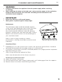
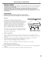
Maintenance
The ventilation hood should be cleaned regularly
using a mild, liquid detergent and a clean soft cloth
to avoid a build-up of grease occurring. Avoid
the use of corrosive chemicals, abrasive cleaning
products, hard brushes and steel wool pads. Grease
deposits are corrosive which can cause damage to
your ventilation hood.
Note: in areas of high humidity or coastal
environments, cleaning should be carried out more
frequently.
Aluminium filters
Depending on use, and at least once a month, the aluminium grease filters should be
removed and cleaned with hot soapy water or in a dishwasher.
If washed in a dishwasher, the filters should be placed in an upright position to prevent
food from falling on them.
After rinsing and drying, replace the filters.
Note: some discoloration of the frames may occur.
Removing the aluminium filters:
1 Open the stainless steel panel.
2 Pull the relative filter catch, tilting it downwards until it disengages from the supports.
3 Reverse these instructions when refitting the filters.

17
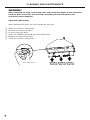
WARNING!
When replacing the bulb, let the bulb cool, and assure that power to the ventilation
hood has been turned off. Use new bulbs according to that indicated on the
ventilation hood nameplate.
Light bulb replacement
Note: replacement bulbs are not covered by warranty.
1 Open the stainless steel panel.
2 Remove the aluminum filters.
3 Unscrew the light bulb.
4 Insert the replacement bulb into the lamp socket.
5 Replace the aluminium filters.
6 Close the stainless steel panel.
CLEANING AND MAINTENANCE
Bulb replacement

18
PARTS AND ACCESSORIES
ITEM REFERENCE NUMBER
LED bulb 792966
Aluminum filter 792429
EN
La page est en cours de chargement...
La page est en cours de chargement...
La page est en cours de chargement...
La page est en cours de chargement...
La page est en cours de chargement...
La page est en cours de chargement...
La page est en cours de chargement...
La page est en cours de chargement...
La page est en cours de chargement...
La page est en cours de chargement...
La page est en cours de chargement...
La page est en cours de chargement...
La page est en cours de chargement...
La page est en cours de chargement...
La page est en cours de chargement...
La page est en cours de chargement...
La page est en cours de chargement...
La page est en cours de chargement...
La page est en cours de chargement...
La page est en cours de chargement...
La page est en cours de chargement...
La page est en cours de chargement...
La page est en cours de chargement...
La page est en cours de chargement...
La page est en cours de chargement...
La page est en cours de chargement...
La page est en cours de chargement...
La page est en cours de chargement...
-
 1
1
-
 2
2
-
 3
3
-
 4
4
-
 5
5
-
 6
6
-
 7
7
-
 8
8
-
 9
9
-
 10
10
-
 11
11
-
 12
12
-
 13
13
-
 14
14
-
 15
15
-
 16
16
-
 17
17
-
 18
18
-
 19
19
-
 20
20
-
 21
21
-
 22
22
-
 23
23
-
 24
24
-
 25
25
-
 26
26
-
 27
27
-
 28
28
-
 29
29
-
 30
30
-
 31
31
-
 32
32
-
 33
33
-
 34
34
-
 35
35
-
 36
36
-
 37
37
-
 38
38
-
 39
39
-
 40
40
-
 41
41
-
 42
42
-
 43
43
-
 44
44
-
 45
45
-
 46
46
-
 47
47
-
 48
48


Fisher & Paykel HP24ILTX2 Mode d'emploi
- Catégorie
- Hottes
- Taper
- Mode d'emploi
- Ce manuel convient également à
dans d''autres langues
- English: Fisher & Paykel HP24ILTX2 User guide