
KERN & Sohn GmbH
Tel: +49-[0]7433- 9933-0
Fax: +49-[0]7433-9933-149
Internet: www.kern-sohn.com
Installationsanleitung
Assembly instructions
Istructions d’installation
KERN KUM-01
TYKUM-01-A
Version 1.1
2023-06
TYKUM-01-A-IA-def-2311


TYKUM-01-A-IA-def-2311 1
Deutsch
D
RS-232-Modul
Version 1.1 2023-06
Installationsanleitung
Inhaltsverzeichnis
1 Lieferumfang .................................................................................................. 2
2 Allgemeine Hinweise und Sicherheitshinweise .......................................... 2
3 Installation ...................................................................................................... 3
3.1 Öffnen des Terminals ............................................................................................................... 3
3.2 Übersicht über die Platine ....................................................................................................... 4
3.3 Installation des Moduls ............................................................................................................ 5
3.4 Schließen des Terminals ......................................................................................................... 9
3.5 Einrichtung der Schnittstelle ................................................................................................ 10

2 TYKUM-01-A-IA-def-2311
Deutsch
1 Lieferumfang
• RS-232-Modul
• Schnittstellenkabel
• Ferritkern
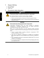
2 Allgemeine Hinweise und Sicherheitshinweise
⚠ GEFAHR
Elektrischer Schlag durch Berühren spannungsführender Bauele-
mente
Elektrischer Schlag führt zu schweren Verletzungen oder Tod
Trennen Sie das Gerät vor dem Öffnen von der Netzspannung.
Führen Sie Installationsarbeiten nur an von der Netzspannung ge-
trennten Geräten durch.
HINWEIS
Elektrostatisch gefährdete Bauelemente
Elektrostatische Entladung (ESD) kann zu Schäden an elektronischen
Bauelementen führen. Beschädigte Bauelemente führen nicht immer so-
fort zu Fehlfunktionen, sondern manchmal erst nach einiger Zeit.
Treffen Sie daher Vorkehrungen zum ESD-Schutz, bevor Sie gefährdete
Bauelemente aus der Verpackung entnehmen und Arbeiten im Elektro-
nikbereich durchführen:
Erden Sie sich, bevor Sie elektronische Bauelemente berühren (ESD-
Kleidung, -Armband, -Schuhe etc.).
Führen Sie Arbeiten an elektronischen Bauelementen nur an geeigne-
ten ESD-Arbeitsplätzen (EPA) mit geeigneten ESD-Werkzeugen
durch (Antistatik-Matte, Leitfähige Schraubendreher etc.).
Transportieren Sie elektronische Bauelemente außerhalb der EPA nur
in geeigneten ESD-Verpackungen.
Entnehmen Sie elektronische Bauelemente niemals aus ihrer Verpa-
ckung, wenn Sie sich außerhalb der EPA befinden.

TYKUM-01-A-IA-def-2311 3
Deutsch
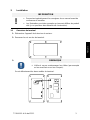
3 Installation
INFORMATION
• Beachten Sie unbedingt die Hinweise in dieser Anleitung bevor Sie
mit der Arbeit beginnen.
• Bei den Abbildungen handelt es sich um Beispiele, die vom realen
Produkt abweichen können (z.B. Positionen der Bauelemente).
3.1 Öffnen des Terminals
1. Gerät von der Netzspannung trennen.
2. Schrauben auf der Rückseite des Terminals lösen.
3.
HINWEIS
Achten Sie darauf, dass Sie keine Kabel beschädigen
(z.B. durch Abreißen oder Einklemmen).
Beide Hälften des Terminals vorsichtig aufklappen.

4 TYKUM-01-A-IA-def-2311
Deutsch
3.2 Übersicht über die Platine
Die Platine bestimmter Anzeigegeräte bietet mehrere Steckplätze für KERN-Zubehör,
mit welchem Sie den Funktionsumfang Ihres Gerätes bei Bedarf erweitern können.
Informationen hierzu finden Sie auf unserer Homepage: www.kern-sohn.com
Auf der oberen Abbildung sind beispielhaft verschiedene Steckplätze abgebildet. Es
gibt drei Steckplatz-Größen für optionale Module: S, M, L. Diese weisen eine bes-
timmte Anzahl an Pins auf.
Die richtige Position für Ihr Modul erfahren Sie über die Größe und Anzahl der Pins
(z.B. Größe L, 6 Pin), welche in den jeweiligen Installationsschritten beschrieben wird.
Bei mehreren identischen Steckplätzen auf der Platine ist es egal, welchen Steckplatz
Sie von diesen auswählen. Das Gerät erkennt automatisch um welches Modul es sich
handelt.


6 TYKUM-01-A-IA-def-2311
Deutsch
5. Modul mit den Schrauben befestigen.
6.
HINWEIS
Öffnen Sie nicht die Druckausgleichsschraube am Termi-
nal. Diese erkennen Sie an den Kondenslöchern im
Schraubenkopf. Eine Entfernung kann zu Feuchtigkeit im
Gerät und somit zu Schäden führen.
Öffnen Sie eine freie Verschlusskappe einer Kabeldurchführung auf der Rück-
seite des Terminals.
Standardmäßig befindet sich eine freie vorbereitete Kabeldurchführung mit Ver-
schlusskappe am Terminal. Eine zusätzliche Kabeldurchführung ist mit einer
Schraube verschlossen. Zur Verwendung dieser Kabeldurchführung ist optiona-
les Zubehör notwendig. Informationen hierzu finden Sie auf unserer Homepage:
www.kern-sohn.com

TYKUM-01-A-IA-def-2311 7
Deutsch
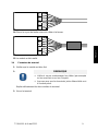
7. Entfernen Sie den Dichtungsstift der Kabeldurchführung.
8. Schnittstellenkabel mit den Leitungsadern durch die Verschlusskappe führen.
9. Schnittstellenkabel mit den Leitungsadern von außen durch die Kabeldurchfüh-
rung durchführen, sodass die Leitungsadern im inneren des Gehäuses liegen.
10. Schnittstellenkabel ca. 15 cm in das Gehäuse hinein ziehen
11. Verschlusskappe der Kabeldurchführung festschrauben.

8 TYKUM-01-A-IA-def-2311
Deutsch
12.
HINWEIS
Achten Sie beim Anschluss an die Kabelklemmen auf die
richtige Farbkennzeichnung (gemäß IEC 60757).
Leitungsadern in die Kabelklemmen des Moduls einführen.
IEC 60757
Farbe
RD
rot
GY
grau
GN
grün
BU
blau
BK
schwarz
YE
gelb
VT
violett
BN
braun
13. Schrauben der Kabelklemmen leicht anziehen, dass die Kontaktspitzen fixiert
sind.

TYKUM-01-A-IA-def-2311 9
Deutsch
14. Ferritkern um das Kabel legen und schließen.
15. Das Modul wurde installiert.
3.4 Schließen des Terminals
1. Modul auf festen Sitz überprüfen.
2.
HINWEIS
Achten Sie darauf, dass Sie keine Kabel beschädigen
(z.B. durch Abreißen oder Einklemmen).
Stellen Sie sicher, dass eventuell vorhandene Dichtun-
gen an Ihrem vorgesehenen Platz sind.
Beide Hälften des Terminals vorsichtig zusammenklappen.
3. Terminal zusammenschrauben.

10 TYKUM-01-A-IA-def-2311
Deutsch
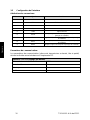
3.5 Einrichtung der Schnittstelle
Anschlussbelegung:
Pin-Nr.
Signal
Funktion
1
VB
6.5 V
2
TXD
Daten ausgeben
3
RXD
Daten empfangen
4
N/A
N/A
5
GND
Signal Ground
6
LED R
High Signal (Signallicht für Checkweighing)
7
LED G
OK Signal (Signallicht für Checkweighing)
8
LED Y
Low Signal (Signallicht für Checkweighing)
9
BEEP
Beeper (Signalton für Checkweighing)
Kommunikationsparameter:
Kommunikationsparameter (Baudrate, Bits und Parität) von Waage und Drucker / PC
müssen übereinstimmen.
Schnittstelle: RS-232 (Werkseinstellung)
Baudrate
9600
Datenbits
8
Stopbits
1
Parität
keine

TYKUM-01-A-IA-def-2311 1
English
GB
RS-232-Module
Version 1.1 2023-06
Installation Instructions
Contents
1 Scope of delivery ........................................................................................... 2
2 General and safety information .................................................................... 2
3 Installation ...................................................................................................... 3
3.1 Opening the terminal ................................................................................................................ 3
3.2 Overview of the circuit board .................................................................................................. 4
3.3 Installing the module ................................................................................................................ 5
3.4 Closing the terminal ................................................................................................................. 9
3.5 Set up the interface ................................................................................................................ 10

2 TYKUM-01-A-IA-def-2311
English
1 Scope of delivery
• RS-232-Module
• Interface cable
• Ferrite core
2 General and safety information
⚠ DANGER
The electrical shock caused by touching live components
An electrical shock results in serious injury or death.
Before opening the device, disconnect it from the power source.
Only perform installation work on devices that are disconnected from
the power source.
NOTICE
Electrostatically endangered structural components
Electrostatic Discharge (ESD) can cause damage to electronic
components. A damaged component may not always malfunction
immediately but may take some time to do so.
Make sure to take precautions for ESD protection before removing
hazardous components from their packaging and working in the electronic
area:
Ground yourself before touching electronic components (ESD
clothing, wristband, shoes, etc.).
Only work on electronic components at suitable ESD workplaces
(EPA) with suitable ESD tools (antistatic mat, conductive screwdrivers,
etc.).
When transporting electronic components outside the EPA, only use
suitable ESD packaging.
Do not remove electronic components from their packaging when they
are outside the EPA.

TYKUM-01-A-IA-def-2311 3
English
3 Installation
INFORMATION
• It is important to follow the instructions in this manual before
starting work.
• The illustrations shown are examples and may differ from the
actual product (e.g. positions of the components).
3.1 Opening the terminal
1. Disconnect the device from the power source.
2. Loosen the screws on the back of the terminal.
3.
NOTICE
Make sure that you do not damage any cables (e.g. by
tearing them off or pinching them).
Carefully open both halves of the terminal.

4 TYKUM-01-A-IA-def-2311
English
3.2 Overview of the circuit board
The circuit board of certain display devices offers several slots for KERN accessories,
which allow you to extend the range of functions of your device if necessary.
Information on this can be found on our homepage: www.kern-sohn.com
The illustration above shows examples of the various slots. There are three slot sizes
for optional modules: S, M, L. These have a certain number of pins.
The correct position for your module is determined by the size and number of pins (e.g.
size L, 6 pins), which is described in the respective installation steps.
If you have several identical slots on the board, it does not matter which slot you select
from these. The device automatically recognises which module it is.


6 TYKUM-01-A-IA-def-2311
English
5. Secure the module with the screws.
6.
NOTICE
Do not open the pressure compensation screw on the
terminal. This can be recognised by the condensation
holes in the screw head. Removing it can lead to moisture
in the device and therefore to damage.
Open a free sealing cap of a cable gland on the back of the terminal.
The standard version of the terminal has a free prepared cable gland with a
sealing cap. An additional cable gland is closed with a screw. In order to use this
cable gland, it is necessary to have optional accessories. Information on this can
be found on our homepage: www.kern-sohn.com

TYKUM-01-A-IA-def-2311 7
English
7. Remove the sealing pin of the cable gland.
8. Use the cable cores to guide the interface cable through the sealing cap.
9. Use the cable cores to lead the interface cable through the cable gland from the
outside so that the cable cores are inside the enclosure.
10. Insert about 15 cm of the interface cable into the enclosure.
11. Tighten the sealing cap of the cable gland.

8 TYKUM-01-A-IA-def-2311
English
12.
NOTICE
Make sure to use the correct colour coding (according to
IEC 60757) when connecting to the cable terminals.
Insert the cable cores into the cable terminals of the module.
IEC 60757
Color
RD
red
GY
grey
GN
green
BU
blue
BK
black
YE
yellow
VT
purple
BN
brown
13. Carefully tighten the screws of the cable terminals so that the contact tips are
fixed.
La page est en cours de chargement...
La page est en cours de chargement...
La page est en cours de chargement...
La page est en cours de chargement...
La page est en cours de chargement...
La page est en cours de chargement...
La page est en cours de chargement...
La page est en cours de chargement...
La page est en cours de chargement...
La page est en cours de chargement...
La page est en cours de chargement...
La page est en cours de chargement...
-
 1
1
-
 2
2
-
 3
3
-
 4
4
-
 5
5
-
 6
6
-
 7
7
-
 8
8
-
 9
9
-
 10
10
-
 11
11
-
 12
12
-
 13
13
-
 14
14
-
 15
15
-
 16
16
-
 17
17
-
 18
18
-
 19
19
-
 20
20
-
 21
21
-
 22
22
-
 23
23
-
 24
24
-
 25
25
-
 26
26
-
 27
27
-
 28
28
-
 29
29
-
 30
30
-
 31
31
-
 32
32


dans d''autres langues
- English: KERN TYKUM-01-A Installation guide
- Deutsch: KERN TYKUM-01-A Installationsanleitung
Documents connexes
-
KERN TYKUM-01-A Guide d'installation
-
-
-
-
-
-
-
-
-