Faber DIAMIS36SS Installation Instructions (PDF)
- Catégorie
- Hottes
- Taper
- Installation Instructions (PDF)

Version 07/11 - Page 1
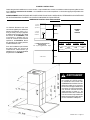
Diamante Isola
(LED electronic controls)
Island Mount Canopy Rangehood
• Installation Instructions
• Use and Care Information
READ AND SAVE THESE INSTRUCTIONS
The Installer must leave these instructions with the homeowner. The
homeowner must keep these instructions for future reference and for
local electrical inspectors' use.
READ THESE INSTRUCTIONS BEFORE YOU START INSTALLING THIS RANGEHOOD
WARNING: - TO REDUCE THE RISK OF A RANGE TOP GREASE FIRE:
a) Never leave surface units unattended at high settings. Boilovers cause smoking and greasy spillovers that may ignite.
Heat oils slowly on low or medium setting.
b) Always turn hood ON when cooking at high heat or when ambeing food
(i.e. Crepes Suzette, Cherries Jubilee, Peppercorn Beef Flambé).
c) Clean ventilating fans frequently. Grease should not be allowed to accumulate on fan or lter.
d) Use proper pan size. Always use cookware appropriate for the size of the surface element.
WARNING: - TO REDUCE THE RISK OF INJURY TO PERSONS IN THE EVENT OF A RANGE TOP GREASE FIRE, OBSERVE
THE FOLLOWING (*):
a) SMOTHER FLAMES with a close-tting lid, cookie sheet, or metal tray, then turn off the burner. BE CAREFUL TO PRE-
VENT BURNS. If the ames do not go out immediately EVACUATE AND CALL THE FIRE DEPARTMENT.
b) NEVER PICK UP A FLAMING PAN - You may be burned.
c) DO NOT USE WATER, including wet dishcloths or towels - a violent steam explosion will result.
d) Use an extinguisher ONLY if:
1) You know you have a Class ABC extinguisher, and you already know how to operate it.
2) The re is small and contained in the area where it started.
3) The re department is being called.
4) You can ght the re with your back to an exit.
(*) Based on “Kitchen Firesafety Tips” published by NFPA.
ALL WALL AND FLOOR OPENINGS WHERE THE RANGEHOOD IS INSTALLED MUST BE SEALED.
This rangehood requires at least 24" of clearance between the bottom of the rangehood and the cooking surface or countertop.
This minimum clearance may be higher depending on local building code. For example, for gas ranges, a minimum of 30" is
recommened and may be required. Overhead cabinets on both sides of this unit must be a minimum of 18" above the cooking
surface or countertop. Consult the cooktop or range installation instructions given by the manufacturer before making any
cutouts.
LISEZ BIEN CETTE FICHE AVANT D'INSTALLER LA HOTTE
AVERTISSEMENT - POUR MINIMISER LE RISQUE D’UN FEU DE GRAISSE SUR LA TABLE DE CUISSON : a) Ne jamais laisser
un élément de la table de cuisson fonctionner sans surveillance à la puissance de chauffage maximale; un renversement/
débordement de matière graisseuse pourrait provoquer une inammation et le génération de fumée. Utiliser toujours une
puissance de chauffage moyenne ou basse pour le chauffage d’huile. b) Veiller à toujours faire fonctionner le ventilateur
de la hotte lors d’une cuisson avec une puissance de chauffage élevée ou lors de la cuisson d’un mets à amber (i.e.
Crepes Suzette, Cherries Jubilee, Peppercorn Beef Flambé). c) Nettoyer fréquemment les ventilateurs d’extraction. Veiller
à ne pas laisser de la graisse s’accumuler sur les surfaces du ventilateur ou des ltres. d) Utiliser toujours un ustensile
de taille appropriée. Utiliser toujours un ustensile de taille adapté à la taille de l’élément chauffant.
AVERTISSEMENT: - POUR PRÉVENIR LES BLESSURES EN CAS DE FEU SUIVRE LES RECOMMANDATIONS SUIVANTES
(*): a) ÉTOUFFEZ LE FEU avec un couvercle métallique et fermez le brûleur. Si le feu ne s'éteint pas tout de suite, QUIT-
TEZ LES LIEUX ET APPELEZ LES POMPIERS. b) NE TOUCHEZ JAMAIS UNE CASSEROLE EN FLAMMES. c) N'UTILISEZ
JAMAIS DE L'EAU ou un torchon mouillé pour éteindre le feu - ce qui pourrait causer une explosion de vapeur. d) N'utilisez
un extincteur que si: 1. Vous avez un modèle ABC et vous connaissez bien son mode d'emploi. 2. Le feu est petit et peu
répandu. 3. Les pompiers sont déjà prévenus. 4. Vous avez une sortie derrière vous. (*) Basé sur la "cuisine Firesafety
incline" édité par NFPA.
TOUTE OUVERTURE DANS LE MUR OU LE PLANCHER À PROXIMITÉ DE LA HOTTE DOIT ÊTRE SCELLÉ
Gardez 24 po. de hauteur entre le bas de la hotte et la surface de cuisson. Cette hauteur minimum peut être plus haute suivant
le code municipal. Par exemple, les cuisinières à gaz peuvent requérir 30 po. de hauteur. Les armoires au-dessus de chaque
côté devront être au moins à 18 po. au-dessus de la surface de cuisson. Consultez la che technique avant de découper les
armoires.

Version 07/11 - Page 2
VENTING REQUIREMENTS
Determine which venting method is best for your application.
Ductwork can extend either through the wall or the roof.
The length of the ductwork and the number of elbows should
size of the ductwork should be uniform. Do not install two
elbows together. Use duct tape to seal all joints in the ductwork
around the cap.
Flexible ductwork is not recommended. Flexible ductwork
creates back pressure and air turbulence that greatly
reduces performance.
for exhaust duct before making cutouts. Do not cut a joist or
stud unless absolutely necessary. If a joist or stud must be
cut, then a supporting frame must be constructed.
FOR MORE SPECIFIC DUCTWORK INFORMATION, GO TO
PAGE 4.
WARNING - To Reduce The Risk Of Fire, Use Only Metal
Ductwork.
ELECTRICAL REQUIREMENTS
A 120 volt, 60 Hz AC-only electrical supply is required on a
separate 15 amp fused circuit. A time-delay fuse or circuit
breaker is recommended. The fuse must be sized per local
codes in accordance with the electrical rating of this unit as
CONNECTED WITH COPPER WIRE ONLY. Wire sizes must
conform to the requirements of the National Electrical Code,
ANSI/NFPA 70 - latest edition, and all local codes and ordi-
nances. Wire size and connections must conform with the
rating of the appliance. Copies of the standard listed above
may be obtained from:
National Fire Protection Association
Quincy, Massachusetts 02269
home.
other enclosed space.
ventilation air.
This appliance should be connected directly to the fused
nonmetallic sheathed copper cable. Allow some slack in the
cable so the appliance can be moved if servicing is ever neces-
at each end of the power supply cable (at the appliance and
at the junction box).
wall. A hole cut through wood must be sanded until smooth.
A hole through metal must have a grommet.
WARNING - TO REDUCE THE RISK OF FIRE OR ELECTRIC
SHOCK, do not use this fan with any solid-state speed
control device.
WARNING - TO REDUCE THE RISK OF FIRE, ELECTRI-
CAL SHOCK, OR INJURY TO PERSONS, OBSERVE THE
FOLLOWING: Use this unit only in the manner intended
by the manufacturer. If you have any questions, contact
the manufacturer.
Before servicing or cleaning unit, switch power off at
service panel and lock the service disconnecting means
to prevent power from being switched on accidentally.
When the service disconnecting means cannot be locked,
securely fasten a prominent warning device, such as a tag,
to the service panel.
CAUTION: For General Ventilating Use Only. Do Not Use To
Exhaust Hazardous or Explosive Materials and Vapors.
WARNING - TO REDUCE THE RISK OF FIRE, ELECTRI-
CAL SHOCK, OR INJURY TO PERSONS, OBSERVE THE
FOLLOWING: Installation Work And Electrical Wiring Must
Be Done By Qualied Person(s) In Accordance With All
Applicable Codes And Standards, Including Fire-Rated
Construction.
Sufcient air is needed for proper combustion and exhaust-
ing of gases through the ue (chimney) of fuel burning
equipment to prevent backdrafting. Follow the heating
equipment manufacturer's guideline and safety standards
such as those published by the National Fire Protection
Association (NFPA), and the American Society for Heating,
Refrigeration and Air Conditioning Engineers (ASHRAE),
and the local code authorities.
When cutting or drilling into wall or ceiling, do not damage
electrical wiring and other hidden utilities.
Ducted fans must always be vented to the outdoors.
WARNING
nonmetallic gaskets or other materials, DO NOT
use for grounding.
circuit. A fuse in the neutral or grounding circuit
could result in electrical shock.
doubt as to whether the rangehood is properly
grounded.
WARNING
For residential use only.
!
!
Cold Weather installations
An additional back draft damper should be installed to minimize
backward cold air ow and a nonmetallic thermal break should
be installed to minimize conduction of outside temperatures
as part of the vent system. The damper should be on the cold
air side of the thermal break. The break should be as close as
possible to where the vent system enters the heated portion
of the house.

Version 07/11 - Page 3
RÈGLEMENTS D'ÉVACUATION
le toit.
Utilisez une longueur de tuyauterie minimale avec les moindres
du calfeutrage.
Utilisez un tuyau d'évacuation rigide lorsque possible.
Un tuyau exible égale deux fois plus qu'un tuyau rigide,
ce qui réduit la puissance d'évacuation.
RÈGLEMENTS D'ÉVACUATION ADDITIONELL - PAGE 11.
AVERTISSEMENT - Pour Ne Pas Risquer Un Feu, Utilisez
Seulement Les Matériaux Métalliques.
AVERTISSEMENT - POUR RÉDUIRE LE RISQUE
D'INCENDIE OU DE CHOC ELECTRIQUE, ne pas utiliser
ce ventilateur en conjonction avec un dispositif de réglage
de vitesse à semi-conducteurs.
AVERTISSEMENT – POUR MINIMISER LES RISQUES
D’INCENDIE, CHOC ÉLECTRIQUE OU DOMMAGES
CORPORELS, OBSERVER LES PRESCRIPTIONS
SUIVANTES: Suivez les recommandations du fabricant
et entre en communication avec lui pour toute
information.
Fermez le courant avant tout entretien et veillez a ce qu'il
reste fermé. Si on ne peut pas verrouiller le panneaux
du service électrique, afchez un avis de danger sur la
porte.
AVIS: Pour L'évacuation Générale - Veillez à Ne Pas
Evacuer Des Matériaux Ou Vapeurs Explosif.
AVERTISSEMENT – POUR MINIMISER LES RISQUES
D’INCENDIE, CHOC ÉLECTRIQUE OU DOMMAGES
CORPORELS, OBSERVER LES PRESCRIPTIONS
SUIVANTES: L'installation Et Le Raccordement Electrique
Doivent Se Faire Par Un Technicien Qualié Selon Tous
Les Codes Municipaux.
An d'obtenir un rendement maximal en ce qui a trait à la
combustion ainsi qu'à l'évacuation des gaz par la conduite
de cheminée, une bonne aération est nécessaire pour
tous les appareils à combustion. Suivez les conseils et
mesures de sécurité du fournisseur tels que ceux publiés
par l'Association Nationale de la Sauvegarde contre
l'Incendie et l'Association Américaine d'Ingénieurs de
Chauffage, Frigorifaction et Air Climatisé ainsi que les
codes municipaux.
En perçant un mur veillez à ne pas perforer un autre l
électrique.
Une ventilateur à évacuation extérieure doit être
raccordée à l'extérieur.
AVERTISSEMENT
pouces.
occasionner un feu.
FICHE TECHNIQUE ÉLECTRIQUE
recommande un coupe-circuit. La taille du fusible doit se
informations chez:
Quincy, Massachusetts 02269
Raccordez cet appareil directement au coupe-circuit avec un
occasionner un feu.
AVERTISSEMENT
Uniquement pour usage menager.
!
!
Installations pour régions à climat froid
On devrait installer un clapet antireux additionnel pour minimiser le
reux d'air froid, et incorporer un élément non métallique d'isolation
thermique pour minimiser la conduction de chaleur par l'intermédiaire
du conduit d'évacuation, de l'intérieur de la maison à l'extérieur.
Le clapet anti-reux doit être placé du côté air froid par rapport
à l'élément d'isolation thermique. L'isolant thermique doit être
aussi proche que possible de l'endroit où le système d'évacuation
s'introduit dans la partie
chauffée de la maison.

Version 07/11 - Page 4
TOOLS NEEDED FOR INSTALLATION
PARTS SUPPLIED FOR INSTALLATION
PARTS NEEDED FOR INSTALLATION
OPTIONAL ACCESSORIES AVAILABLE
High Ceiling Chimney Kit
Extends the island chimney for high
ceilings
part # HIGHDIAMIS - Stainless
*Ductless Conversion Kit
For non-vented installations only
* it is highly recommended that professional
style cooking always be vented to the
outside
part # DUCTDIAMIS - Stainless
Replacement Charcoal Filter
For non-vented installations only,
part # FILTER2
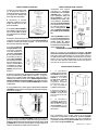
UNPACK THE RANGEHOOD
make sure that no mounting hardware or parts are missing. DO NOT REMOVE THE PLASTIC COVERING ON THE CHIMNEYS
AT THIS TIME! This plastic covering protects the chimney from scratches during installation.
For safe packaging, the entire chimney section of the hood is shipped assembled. It must be disassembled completely for
installation. Disassemble packaged chimney components by sliding apart the chimney covers (B and C in FIGURE 1). Remove
the LOWER CHIMNEY COVER (B) from the CHIMNEY SUPPORT (D) by removing the 2 philips screws on the outside bottom
of the chimney cover. Remove the UPPER CHIMNEY COVER (C) from the CHIMNEY SUPPORT (D) by removing the 2 philips
screws on the outside top of the chimney cover.
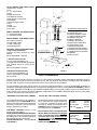
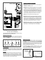
CALCULATE THE DUCTRUN LENGTH
The ductrun should not exceed 35 equivalent
feet if ducted with the required minimum of
ductwork by adding the equivalent feet in
FIGURE 2 for each piece of duct in the system.
An example is given in FIGURE 3.
For best results, use no more than three 90°
elbows. Make sure that there is a minimum
of 24" of straight duct between elbows if
more than one is used. Do not install two
elbows together. If you must elbow right
away, do it as far away from the hood's
exhaust opening as possible.
9 Feet Straight Duct
Wall Cap
Total System
FIGURE 3
3.0 feet
5.0 feet
12.0 feet
0.0 feet
Wall Cap
FIGURE 2
9.0 feet
10.0 feet
0.0 feet
19.0 feet
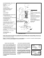
PREPARING TO ATTACH THE CHIMNEY
The rangehood attaches to the ceiling by a
metal support structure (D in FIGURE 1). This
support must be attached to the ceiling before
the canopy is attached. This structure must
FOR WOOD CEILINGS:
wood screws and washers.
FOR PLASTER OR SHEET ROCK CEILINGS:
If possible, the support must be attached to
the ceiling joists. If not, a supporting structure
behind the sheet rock must be built.
FOR WOOD SHELVES: Use items F, G, &
H in FIGURE 1.
FIGURE 1
RANGEHOOD COMPONENTS
A. CANOPY SECTION
B. LOWER CHIMNEY COVER
C. UPPER CHIMNEY COVER
D. CHIMNEY SUPPORT
E. CANOPY SCREWS
F.
G. WOOD SHELF WASHERS
H. WOOD SHELF NUTS
I. MOUNTING TEMPLATE
J.
K.
L
M. DAMPER
N
H
I
G
L
N
M
K
J

Version 07/11 - Page 5
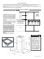
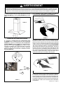
upper
chimney
cover
lower
chimney
cover
canopy
cabinet base
x = distance from hood to cooktop
(varies depending on installation)
min - 24”, suggested max - 30”
also consult cooktop
3 3/8” min
15 3/8” max
23
5/8”
3 3/16”
36”
FIGURE 4
DUCTED
DIMENSIONS
x
min & max ceiling height examples
x = 30"
min
max
x = 28"
min
max
x = 26"
min
max
x = 24"
min
max
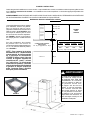
The Diamante Isola chimney is highly
adjustable and designed to meet varying
ceiling heights as indicated in FIGURE 4.
The chimney can be adjusted for ceilings
on the distance between the bottom of
the hood and the cooktop (distance x in
FIGURE 4).
For higher ceiling installations, the High
Ceiling Chimney Kit includes an additional
ceiling heights in FIGURE 4.
DUCTED INSTALLATION DIMENSIONS
(vented to the outside)
PLAN THE INSTALLATION
This rangehood can be installed as either ducted or ductless. When installed ductless, the rangehood vents out of a grate on
the back of the lower chimney. Ductless installations require a Ductless Conversion Kit, available from your dealer.
WARNING!
USED AND CAREFULLY CALCULATE ALL MEASUREMENTS.
WARNING
AND WEIGHT OF THIS
RANGEHOOD, THE
FIRMLY ATTACHED TO
THE CEILING. For plaster
or sheet rock ceilings, the
support must be attached
to the joists. If this is
not possible, a support
structure must be built
behind the plaster or sheet
rock. The manufacturer
assumes no responsibility
for injury or damage caused
by improper installations.
!
11 7/16"
NOTE: To reduce the chimney
structure to the 27" minimum height
as shown, the middle section of the
support structure (FIGURE 5) needs
to be removed. Out of the box, the
minimum chimney length is 32", not
27" as shown in the dimensional
diagram. Add 5" to all minimum
ceiling height calculations if keeping
the middle section in place. Contact
Faber at
508-358-5353 for more information.
FIGURE 5

Version 07/11 - Page 6
PLAN THE INSTALLATION
This rangehood can be installed as either ducted or ductless. When installed ductless, the rangehood vents out of grates on
either side of the lower chimney. Ductless installations require a Ductless Conversion Kit, available from your dealer.
WARNING!
USED AND CAREFULLY CALCULATE ALL MEASUREMENTS.
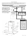
The ductless Diamante Isola chimney is
adjustable for varying ceiling heights as
indicated in FIGURE 6. The chimney can be
between the bottom of the hood and the
cooktop (distance x in FIGURE 6).
For higher ceiling installations, the High
Ceiling Chimney Kit includes an additional
various ceiling heights in FIGURE 6.
upper
chimney
cover
ductless
lower
chimney
cover
canopy
cabinet base
x = distance from hood to cooktop
(varies depending on installation)
min - 24”, suggested max - 30”
also consult cooktop
8 3/8” min
15
3/8” max
23
5/8”
36”
FIGURE 6
DUCTLESS
DIMENSIONS
x
min & max ceiling height examples
x = 30"
min
max
x = 28"
min
max
x = 26"
min
max
x = 24"
min
max
DUCTLESS INSTALLATION DIMENSIONS
(not vented to the outside)
12
3 3/16”
3 1/2”
WARNING
AND WEIGHT OF THIS
RANGEHOOD, THE
FIRMLY ATTACHED TO
THE CEILING. For plaster
or sheet rock ceilings, the
support must be attached
to the joists. If this is
not possible, a support
structure must be built
behind the plaster or sheet
rock. The manufacturer
assumes no responsibility
for injury or damage caused
by improper installations.
1
!
11 7/16"

Version 07/11 - Page 7
.
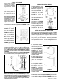
ATTACH THE SUPPORT
4. Determine and make necessary cuts for the ductwork. The duct
opening is shown on the mounting template (L in FIGURE 7). Install
ductwork before mounting the support.
FIGURE 9
FIGURE 7
Ductless installations require
a Ductless Conversion
Kit whose components are
pictured in FIGURE 10. Do
not use the DAMPER (N
in FIGURE 1) for ductless
installations. The LOWER
CHIMNEY COVER (B in
FIGURE 1) should be
discarded and replaced by
the new one with holes from
the Ductless Conversion Kit
(D in FIGURE 10).
As indicated in FIGURE
10, place the DUCTLESS
DIVERTER (A) over the
exhaust opening of the EASY
(E). Fit the DUCTLESS
(B) into the
DIVERTER (A).
FIGURE 10
FIGURE 11
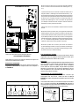
MAKE THE ELECTRICAL CONNECTION
DO NOT
turn on the power until installation is complete! Connect
the Power Supply Cable to the rangehood. Attach the White
lead of the power supply to the White lead of the rangehood
twist-on type wire connector. Connect the Green (Green and
Yellow) ground wire under the Green grounding screw.
1. Put a thick, protective
covering over cooktop,
set-in range or countertop
to protect from damage
or dirt.
2. Determine and clearly
mark with a pencil on
t h e c e i l i n g w h e r e
the rangehood will be
installed.
3. A template (L in FIGURE
7) for mounting the support
is supplied in the carton
with the support. Use this
template to mark holes for
support on the ceiling.
FOR DUCTLESS INSTALLATIONS
1. The UPPER CHIMNEY
COVER (C in FIGURE 11)
attaches using two screws
provided (G in FIGURE 11).
If using the High Ceiling
Chimney Kit, use the
UPPER CHIMNEY COVER
supplied with the kit. Slide
up and attach the UPPER
CHIMNEY COVER.
2. Attach the duct work to
the DAMPER (M in FIGURE
1). Make sure to seal all
joints with duct tape to
prevent leaks.
3. The LOWER CHIMNEY
COVER (B in FIGURE
11) attaches using two
screws provided (G in
FIGURE 11). Install the
LOWER CHIMNEY COVER
by sliding it up over the
support and the UPPER
CHIMNEY COVER.
For ductless installations, line up the DUCTLESS DIVERTER
(B in FIGURE 10) with the holes
in the LOWER CHIMNEY COVER (D in FIGURE 10) and snap
in the VENT GRIDS (C in FIGURE 10).
INSTALLING THE RANGEHOOD
8. Attach the CHIMNEY SUPPORT (D in FIGURE 9) to the ceiling.
the desired length of the support structure and adjust the length of the
support by removing the four screws (indicated in FIGURE 9) with a
install and tighten the four screws.
6. Determine the proper location for the Power Supply Cable as
Run the Power Supply Cable. Use caulking to seal around the
hole. DO NOT turn on the power until installation is complete!
A knockout is provided at the top of the CHIMNEY SUPPORT (D
in FIGURE 9).
7. For ducted installations, place the round DAMPER (N in FIGURE
1) into the exhaust opening of the rangehood and press down.
5. If using the High Ceiling
Chimney Kit, remove
the CHIMNEY COVER
from the CHIMNEY
(A in
FIGURE 8). Position the
over the CHIMNEY
SUPPORT (B in FIGURE
8) so that the outside
edges and the electrical
holes line up. Attach the
the CHIMNEY SUPPORT
using the 4 bolts (C in
FIGURE 8). Tighten bolts
securely.
FIGURE 8

Version 07/11 - Page 8
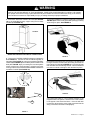
For ductless installations, install the CHARCOAL FILTER (F in
FIGURE 10)
and locking into place. See FIGURE 14
WARNING
Two people must hold the canopy in place while the third person installs the screws that attach the canopy to the chimney.
The manufacturer assumes no responsibility for injury or damage caused by improper installations.
4. From below, attach the CANOPY SECTION (A in FIGURE
12) to the assembled chimney support using the four bolts
provided (F in FIGURE 12).
FIGURE 12
FIGURE 14
6.
turning the knob to the left so that the locking lever does not
(as in FIGURE 15). Insert the opposite
FIGURE 15
7. Turn the power supply on. Turn on blower and lights. If the
rangehood does not operate, check that the circuit breaker
is not tripped or the house fuse blown. If the unit still does
not operate, disconnect the power supply and check that the
wiring connections have been made properly.
5.
A in FIGURE 13
indicated in B in FIGURE 13. Insert the connected CONTROL
(A in FIGURE 13) into the black plastic CONNECTOR
(C in FIGURE 13) by connecting the two black plastic
pieces using the four screws provided. Using the two longer
the METAL FLANGE (D in FIGURE 13).
FIGURE 14
MAKE THE INTERNAL ELECTRICAL CONNECTIONS
C
A
B
D
A
B
!

Version 07/11 - Page 9
WIRING DIAGRAM
FIGURE 17
For Best Results
Start the rangehood several minutes before cooking to develop
after cooking is complete to clear all smoke and odors from
the kitchen.
Cleaning
hot detergent solution or washed in the dishwasher. Stainless
steel cleaner should be used on stainless rangehoods. Abrasives
USE AND CARE INFORMATION
This rangehood system is designed to remove smoke, cooking
vapors and odors from the cooktop area.
Rangehood Control Panel
The control panel is located on the front edge of the rangehood
canopy. The position and function of each control button are
indicated in FIGURE 16.
FIGURE 18
Replacing the Lamps
light switch is turned off. Remove the 2 screws (as indicated
in FIGURE 17) that hold the light support and gently pull the
support down from the hood. Remove the lamp from the light
support and replace with new lamp. Replace the light support
An alternative method to replace the lamps is to use a 1 1/4"
suction cup (FIGURE 18). Attach the suction cup to the bulb and
pull rmly down on the bulb and replace with a new lamp.
0 1 2 3 4 5 6 7 8 9
Creato da.
Rev :
Ver :
DOLCE CORRADO
Materiali: non deveno contenere Pb, Cr6+, Hg, PBB, pbde, ai sensi della direttiva 2002/95 CE
SCHEMA ELETTRICO M8-4V ATL FARETTI
Non rilevare quote dal grafico non app ortare modifiche senza l'autorizzazione d'ufficio progettazion e
a termini di legge ci riserviamo la propr ieta' del presente disegno con divieto di rip roduzione totale o parziale
Code :
Disegno N :
Data:
11.Nov.2010
436005191
H90_065
CN13
CN9
CN12
CN4
CN7
CN1
FASE
NEUTRO
COM
V1
V2
V3
V4
LUC.1 F.LUC.1 F.
LUC.1 N.
LUC.2 F.
LUC.2 N.
LINE IN
120Vac
60Hz ~
L
N
Y-G
WIRING BOX
Y-G
Faber ATL
1
2
3
4
5
7
6
1
2
3
4
BLU
BLK
L-B
RED
BLU
PNK
GRY
BRW
BLK
1
1
BLK
123
6 5 4
789
1 2 3
654
987
RED
M8 4V
120V ~
WHT
2
2
WHT
WHT
BRW
BRW
3
3
BRW
BLU
GRY
4
4
GRY
BLK
BLU
5
5
BLU
ORG
RED
6
6
RED
PNK
7
7
PNK
Y-G
VLT(ORG)
8
8
VLT(ORG)
RED(ORG)
9
9
RED(ORG)
RED
10
10
RED
VLT
11
11
VLT
12
12
TOROIDAL
TRANSFORMER
WHT
4
3
BLK
VLT
RED
2
1
BLK
RED
HALOGEN
LAMPS
ORG
2
1
ORG
4
3
RED
VLT
HALOGEN
LAMPS
HALOGEN
LAMPS
ORG
ORG
RED
HALOGEN
LAMPS
VLT
PRI.
SEC.
ELECTRONIC
TRNSFORMER
FIGURE 16 CONTROLS CONTINUED
Button A. Press button to turn fan on / off. Current speed is
displayed in C display (1, 2, 3)
Button B. Press to reduce fan speed to as low as speed
1, display C shows the speed selected (1, 2, 3). Hold for 3
seconds to turn on 30 minute delay feature which runs the
hood for 30 minutes and automatically shuts the hood off.
Current speed on 30 minute delay is shown in C display with
a blinking light to indicate 30 minute mode. Shut off the 30
minute mode by holding down the button for 3 seconds
Button C. LED single digit readout display screen
Button D. Press button to increase fan speed up to speed 3.
Hold for 3 seconds to activate intensive speed mode which
operates hood on highest speed for 10 minutes and then
returns to previous speed setting. Display C indicates intensive
speed with an "H" and blinking light. Shut off the intensive
speed mode by holding down the button for 3 seconds
Button E. Press the button to turn on and off lighting. Press
once to turn the dimmer light on, press twice to turn the normal
light setting on, and press again to turn off the lighting.
FIGURE 16
A
B
C
D
E

Version 07/11 - Page 10
FABER WARRANTY & SERVICE (SAVE FOR YOUR RECORDS)
All Faber products are warranteed against any defect in materials or workmanship for the
original purchaser for a period of 1 year from the date of original purchase. This warranty
covers labor and replacement parts. To obtain warranty service, contact the dealer from
whom you purchased the rangehood, or the local Faber distributor. If you cannot identify
a local Faber distributor, contact us at (508) 358-5353 for the name of a distributor in your
area.
The Following is not covered by Faber's warranty:
1. Service calls to correct the installation of your range hood, to instruct you how to use your
range hood, to replace or repair house fuses or to correct house wiring or plumbing.
2. Service calls to repair or replace range hood light bulbs, fuses or lters. Those
consumable parts are excluded from warranty coverage.
3. Repairs when your range hood is used for other than normal, single-family
household use.
4. Damage resulting from accident, alteration, misuse, abuse, re, ood, acts of God,
improper installation, installation not in accordance with electrical or plumbing codes, or
use of products not approved by Faber.
5. Replacement parts or repair labor costs for units operated outside the United States or
Canada, including any non-UL or C-UL approved Faber rangehoods.
6. Repairs to the hood resulting from unauthorized modications made to the
rangehood.
7. Expenses for travel and transportation for product service in remote locations and pickup
and delivery charges. Faber range hoods should be serviced in the home.
Record Your Information Below:
Serial #: __________________________
Date of Purchase: ______________

Version 07/11 - Page 11
OUTILS NÉCESSAIRES À L’INSTALLATION
PIÈCES FOURNIES POUR L’INSTALLATION
PIÈCES NÉCESSAIRES POUR L’INSTALLATION
ACCESSOIRES POUR L’INSTALLATION
Haut kit de cheminée de plafond
hauts
part # HIGHDIAMIS - Acier Inoxydable
• *Kit Pour Conversion Du Conduit
Pour installation sans conduit
part # DUCTDIAMIS - Acier Inoxydable
• Filtres au Charbon
Pour installation sans conduit
part # FILTER2
DÉBALLER LA HOTTE
(C de la FIGURE 1)(B de la
FIGURE 1) du TREILIS (D de la FIGURE 1)
CALCUL DE LONGUEUR DU CONDUIT
Calculer la longueur du conduit en ajoutant
FIGURE 2 pour
FIGURE 3.
Pour de meilleurs résultats, ne pas utiliser
plus de trois coudes de 90
o
. S’assurer qu’il
y ait un minimum de 24 po de conduit
droit entre les coudes si l’on utilise plus
d’un coude. Ne pas installer deux coudes
ensemble.
9 pi de conduit droit
Capuchon de mur
FIGURE 3
3,0 pi
5,0 pi
12,0 pi
0,0 pi
Capuchon de mur
FIGURE 2
9,0 pi
10,0 pi
0,0 pi
19,0 pi
INSTALLATION DU SUPPORT
(D de la FIGURE 1). Ce
cette structure supporte le poids de la hotte,
POUR LES PLAFONDS EN PLÂTRE OU EN
sinon, une structure supportante doit être
F, G, & H de
la FIGURE 1.
FIGURE 1
COMPONENTS DE LA HOTTE
A. HOTTE
B.
C.
D. TREILLIS
E. VIS POUR LA HOTTE
F.
G.
H.
I.
J.
K.
L
M. REGISTRE ROND
N
I
M
G
H
N
J
L
K

Version 07/11 - Page 12
couvercle
cheminée
supérieure
couvercle
cheminée
inférieure
hotte
cabinet base
x = distance entre la hotte et la
table de cuisson
min - 24 po, suggested max - 30 po
3 3/8 po min
15 3/8 po max
23
5/8 po
3 3/16 po
36 po
FIGURE 4
AVEC
CONDUIT
x
min & max hauteurs de plafond
x = 30 po
min
8 pi
3/16 po
max
9 pi
3/16 po
x = 28 po
min
7 pi
10 3/16 po
max
8 pi
10 3/16 po
x = 26 po
min
7 pi
8 3/16 po
max
8 pi
8 3/16 po
x = 24 po
min
7 pi
6 3/16 po
max
8 pi
6 3/16 po
DIMENSIONS D’INSTALLATION AVEC CONDUIT
PLAN DE L’INSTALLATION
avec le Kit Pour Conversion Du Conduit.
votre marchand.
AVERTISSEMENT!
entre 7 pi 6 3/16 po and 9 pi 3/16 po
(regardez la distance entre la hotte et la
table de cuisson - X en FIGURE 4). Cela
La FIGURE 4 illustre les dimensions
Isola.
de plafond inclut une structre de
sur le FIGURE 4.
11
7/16"
NOTE : Pour ramener la structure
de cheminée au 27" ; taille minimum
comme montré, la section centrale
de la structure de soutènement
(FIGURE 5) d'être enlevé. Hors de
la boîte, la longueur minimum de
cheminée est 32" , pas 27" ; suivant
les indications du diagramme
dimensionnel. Ajoutez 5" ; à tous les
calculs minimum de taille de plafond
si gardant la section centrale en
place. Contactez Faber à 508-358-
5353 pour plus d'information.
FIGURE 5
à CAUSE DE LA DIMENSION ET
DU POIDS DE CETTE HOTTE,
FERMEMENT AU PLAFOND.
en panneaux muraux secs,
solives. Si cela est impossible,
ou les panneaux muraux secs.
responsable des blessures ou
AVERTISSEMENT
!

Version 07/11 - Page 13
PLAN DE L’INSTALLATION
avec le Kit Pour Conversion Du Conduit.
votre marchand.
AVERTISSEMENT!
couvercle
cheminée
supérieure
couvercle
cheminée
inférieure
hotte
cabinet base
x = distance entre la hotte et la
table de cuisson
min - 24 po, suggested max - 30 po
8 3/8 po min
15 3/8 po max
23
5/8 po
36 po
FIGURE 6
SANS
CONDUIT
x
min & max hauteurs de plafond
x = 30 po
min
8 pi
5 3/16 po
max
9 pi
3/16 po
x = 28 po
min
8 pi
3 3/16 po
max
8 pi
10 3/16 po
x = 26 po
min
8 pi 1 3/16 po
max
8 pi
8 3/16 po
x = 24 po
min
7 pi
11 3/16 po
max
8 pi
6 3/16 po
DIMENSIONS D’INSTALLATION SANS CONDUIT
12 1/2 po
3 3/16 po
3 1/2 po
1
à CAUSE DE LA DIMENSION ET
DU POIDS DE CETTE HOTTE,
FERMEMENT AU PLAFOND. Pour les
aux solives. Si cela est impossible,
panneaux muraux secs. Le fabricant
AVERTISSEMENT
hauteurs de plafond, entre 7 pi 11
3/16 po and 9 pi 3/16 po (regardez
la distance entre la hotte et la table
de cuisson - X en FIGURE 6). Cela
La FIGURE 6 illustre
de plafond inclut une structre de
de plafond sur le FIGURE 6.
!
11 7/16"

Version 07/11 - Page 14
INSTALLATION DU SUPPORT
6.
calfeutrer pour sceller tout autour du trou. NE PAS mettre en circuit
tant que l’installation n’est pas complétée. Une pastille enfonçable
TREILLIS
(D de la FIGURE 9)
7. Pour installations avec conduit, placer le REGISTRE ROND (N de
la FIGURE 1
fortement sur le registre.
FIGURE 9
FIGURE 7
Installations sans conduit
Kit Pour
Conversion Du Conduit
(FIGURE 10)
pas le REGISTRE ROND (N
de la FIGURE 1) pour les
Installations sans conduit.
(B de la FIGURE
1) et replacer avec le couvercle
avec
dans le Kit Pour Conversion
Du Conduit (D de la FIGURE
10).
FIGURE 10, mettre le
DUCTLESS DIVERTER (A) dans
(E). Mettre
le DUCTLESS DIVERTER
(B)
dans le DIVERTER (A).
FIGURE 10
FIGURE 11
BRANCHER LE CÂBLE D'ALIMENTATION
NE PAS
mettre en circuit tant que l’installation n’est pas complétée.
1.
sur la plaque de cuisson, la
2.
la ligne centrale sur le mur où la
3. Un gabarit (L de la FIGURE 7)
pour installer le support est fourni
avec ce dernier. Utiliser ce gabarit
pour marquer les trous du support
au plafond.
INSTALLATIONS SANS CONDUIT
1. Le COUVERCLE
(C
de la FIGURE 11)
les deux vis fournies (G de la
FIGURE 11).
Si en utilisant
Le Haut Kit de Cheminée
de plafond, utilisez
Le
kit. Fixer le COUVERCLE
2.
REGISTRE ROND (M de la
FIGURE 1) et sceller toutes
les connexions avec du ruban
3. Le COUVERCLE
(B de la FIGURE 11)
avec les deux vis fournies
(G de la FIGURE 11). Fixer
Pour installations sans conduit, aligner les DUCTLESS
(B de la FIGURE
10)
(D de la FIGURE 10) et installer les
VENT GRIDS (C de la FIGURE 10).
INSTALLATION DU HOTTE
4.
L de la FIGURE 7).
dan le centre exactement de le treillis.
8. Installer le TREILLIS (D de la FIGURE 9)
(de
la FIGURE 9)
5. Si en utilisant Le Haut Kit de
Cheminée de plafond, enlever
de la PROLONGATION DE
CHEMIN´EE (A de la FIGURE
8). Placez la PROLONGATION
DE CHEMIN´EE au-dessus de
TREILLIS
(B de la FIGURE 8)
Attachez la PROLONGATION
TREILLIS
(C de la
FIGURE 8). Serrez les boulons
solidement.
FIGURE 8

Version 07/11 - Page 15
Pour installations sans conduit, installer le FILTRE AU
(F de la FIGURE 10). Voyez FIGURE 14
AVERTISSEMENT
LA HOTTE.
4.
(F de la FIGURE 12) la HOTTE (A de la FIGURE 12) au treillis
FIGURE 12
FIGURE 14
6.
(de la FIGURE
15)
bouton et le tourner vers la gauche (sens antihoraire) de telle
sorte que le levier de verrouillage ne fasse pas saillie hors du
7.
correctement.
5. Connecter le CONNECTEUR DES COMMANDES (A de
la FIGURE 14) et le CONNECTEURE DES SPOTS (B de la
FIGURE 14)
(A de la FIGURE 14)
plastique noire (C de la FIGURE 14) en reliant les deux
(D de la FIGURE 14).
FIGURE 14
CONNECTER LES CONNECTEURS INTERNE
C
A
B
D
A
B
FIGURE 15
!

Version 07/11 - Page 16
DIAGRAMME DE CÂBLAGE
FIGURE 17
Pour de meilleurs résultats
Mettre la hotte en circuit avant de commencer la cuisson. Laisser
Nettoyage
dans
sur les hottes en acier inoxydable. Ne pas utiliser de produits
Remplacement de la lumière halogène
(de la
FIGURE 17).
ampoule.
Une méthode alternative pour substituer les lampes est d'utiliser
des 1 1/4"tasses d'aspiration (de la FIGURE 18). Attachez la
tasse d'aspiration à l'ampoule et tirez fermement vers le bas sur
l'ampoule et la substituez avec une nouvelle lampe.
UTILISATION ET ENTRETIEN
cuisson et les odeurs de la cuisine.
Panneau de commandes
la FIGURE 16.
FIGURE 18
FIGURE 16
0 1 2 3 4 5 6 7 8 9
Creato da.
Rev :
Ver :
DOLCE CORRADO
Materiali: non deveno contenere Pb, Cr6+, Hg, PBB, pbde, ai sensi della direttiva 2002/95 CE
SCHEMA ELETTRICO M8-4V ATL FARETTI
Non rilevare quote dal grafico non app ortare modifiche senza l'autorizzazione d'ufficio progettazion e
a termini di legge ci riserviamo la propr ieta' del presente disegno con divieto di rip roduzione totale o parziale
Code :
Disegno N :
Data:
11.Nov.2010
436005191
H90_065
CN13
CN9
CN12
CN4
CN7
CN1
FASE
NEUTRO
COM
V1
V2
V3
V4
LUC.1 F.LUC.1 F.
LUC.1 N.
LUC.2 F.
LUC.2 N.
LINE IN
120Vac
60Hz ~
L
N
Y-G
WIRING BOX
Y-G
Faber ATL
1
2
3
4
5
7
6
1
2
3
4
BLU
BLK
L-B
RED
BLU
PNK
GRY
BRW
BLK
1
1
BLK
123
6 5 4
789
1 2 3
654
987
RED
M8 4V
120V ~
WHT
2
2
WHT
WHT
BRW
BRW
3
3
BRW
BLU
GRY
4
4
GRY
BLK
BLU
5
5
BLU
ORG
RED
6
6
RED
PNK
7
7
PNK
Y-G
VLT(ORG)
8
8
VLT(ORG)
RED(ORG)
9
9
RED(ORG)
RED
10
10
RED
VLT
11
11
VLT
12
12
TOROIDAL
TRANSFORMER
WHT
4
3
BLK
VLT
RED
2
1
BLK
RED
HALOGEN
LAMPS
ORG
2
1
ORG
4
3
RED
VLT
HALOGEN
LAMPS
HALOGEN
LAMPS
ORG
ORG
RED
HALOGEN
LAMPS
VLT
PRI.
SEC.
ELECTRONIC
TRNSFORMER
B
C
D
Bouton-poussoir du bouton A. pour tourner le ventilateur "Marche/
Arrêt". La vitesse courante est montrée dans l'afchage de C (1,
2, 3)
La presse du bouton B. pour ramener la vitesse de l'hélice aussi à
bas que la vitesse 1, l'afchage C montre la vitesse choisie (1, 2, 3).
Tenez pendant 3 secondes pour allumer le dispositif minute du retard
30 qui court le capot pendant 30 minutes et ferme automatiquement
le capot au loin. La vitesse courante sur le retard 30 minute est
montrée dans l'afchage de C avec une lumière de clignotement
pour indiquer le mode 30 minute. Coupez le mode 30 minute en
maintenant le bouton pendant 3 secondes.
C.Boutonnez l'écran de visualisation simple de lecture de chiffre
de LED
Boutonnez le bouton-poussoir de D. pour augmenter la vitesse de
l'hélice jusqu'à la prise de la vitesse 3. pendant 3 secondes pour
activer le mode intensif de vitesse qui actionne le capot sur la vitesse
la plus élevée pendant 10 minutes et puis revient à l'arrangement
précédent de vitesse. L'afchage C indique la vitesse intensive avec
un " ; H" ; et lumière de clignotement. Coupez le mode intensif de
vitesse en maintenant le bouton pendant 3 secondes
Boutonnez la presse d' E. le bouton pour tourner en marche et
en arrêt l'allumage. Pressez une fois pour allumer la lumière plus
faible, pressez deux fois pour allumer l'arrangement léger normal,
et pressez encore pour arrêter l'éclairage.
A
E

Version 07/11 - Page 17
FABER GARANTIE ET SERVICE (
ÉCONOMISER POUR VOS ENREGISTREMENTS
)
Faber garantit à l’utilisateur-acheteur d’origine que les produits Faber vendus neufs par nous sont sans vice de
matériel et de main-d’oeuvre d’origine pour une période d’un an à partir de la date d’achat. La garantie couvre
la main-d’oeuvre et les pièces de remplacement. An d’obtenir un service sous garantie, communiquer avec le
marchand où la hotte a été achetée ou le distributeur Faber de la région. Si l’on ne peut trouver de distributeur
Faber, communiquer avec nous au (508) 358-5353 an d’obtenir le nom d’un distributeur dans la région.
Les frais suivants ne sont pas couverts par la garantie Faber :
1. Les appels de service pour corriger l’installation de votre hotte de cuisinière, pour vous indiquer
comment utiliser votre hotte de cuisinière, pour remplacer ou réparer les fusibles de votre maison ou
pour corriger votre câblage ou votre système de plomberie.
2. Les appels de service pour remplacer ou réparer les ampoules, les fusibles ou les
ltres de votre hotte de cuisinière.
3. Les réparations lorsque votre hotte de cuisinière a été utilisée plus que la normale,
c'est-à-dire plus que pour une famille par foyer.
4. Les dommages résultant d’un accident, de l’altération, d’une mal utilisation, d’un acte
de Dieu, d’une installation inappropriée, d’une installation non-conforme aux
normes d’électricité ou de plomberie ou d’une utilisation de l’appareil non approuvée par Faber.
5. Les pièces de remplacement ou les frais de main d’œuvre pour les unités
utilisées en dehors du Canada ou des États Unis, incluant toutes hotte de cuisinière
approuvée par Faber non UL ou C-UL.
6. Les réparations dues à des modications non-autorisées sur votre hotte de cuisinière.
7. Les frais de transport de l’appareil pour réparations à distance.
Enregistrez Votre Information Ci-dessous:
Séquentiel #: __________________________
Date d'achat: ______________
-
 1
1
-
 2
2
-
 3
3
-
 4
4
-
 5
5
-
 6
6
-
 7
7
-
 8
8
-
 9
9
-
 10
10
-
 11
11
-
 12
12
-
 13
13
-
 14
14
-
 15
15
-
 16
16
-
 17
17


Faber DIAMIS36SS Installation Instructions (PDF)
- Catégorie
- Hottes
- Taper
- Installation Instructions (PDF)
dans d''autres langues
- English: Faber DIAMIS36SS
Documents connexes
-
Faber Stilo Isola 36 SS Guide d'installation
-
-
-
-
-
-
-
-