Yamaha A-S1100 Silver/Piano Black Manuel utilisateur
- Catégorie
- Amplificateur d'instruments de musique
- Taper
- Manuel utilisateur

Printed in Malaysia ZQ25580
© 2015 Yamaha Corporation
G
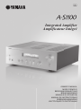
Integrated Amplifier
Amplificateur Intégré
ИНСТРУКЦИЯ ПО ЭКСПЛУАЦИИ
OWNER’S MANUAL
MODE D’EMPLOI
BEDIENUNGSANLEITUNG
BRUKSANVISNING
MANUALE DI ISTRUZIONI
MANUAL DE INSTRUCCIONES
GEBRUIKSAANWIJZING

2 En
A Living Tradition in Sound
A piano comes into this world through the perfect synergy of advanced technical
skill and artistry. Such a piano can create sound that truly reflects the player’s
feelings.
The final stage in piano production is called “voicing”. It is here that the
instrument is given its soul.
A highly skilled expert concentrates his mind and sensitivity on the sound of each
key, finely adjusting the dynamic feel of the hammers, bringing the tone and
vibrancy of all 88 keys together perfectly; a truly stunning achievement.
It is a quality of sound that can only be determined by an astute, sensitive ear. We
apply this very same concept to the manufacture of our audio products. The
technician performs exhaustive listening tests and every component is considered,
in order to finally achieve the ideal sound.
Yamaha’s tradition of audio quality stretches back over 125 years, and continues to
live on in all Yamaha products today.

3 En
NP-S2000
Soavo-1
NS-10M
A-S3000
CD-S3000
NS-20
CA-1000
NS-690
B-1
PX-2
C-2
NS-1000M
A-1
B-6
B-2x
MX-10000
CX-10000
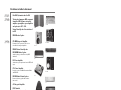
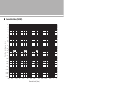
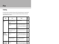
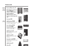
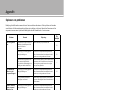
Excellence in Audio Achievement
First HiFi System introduced in 1920
We introduced numerous HiFi components
(turntables, FM/AM tuners, integrated
amplifiers, preamplifiers, power amplifiers
and speakers) in 1955 - 1965.
Natural Sound Speaker Series introduced
in 1967
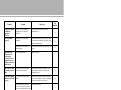
NS-20 Monitor Speaker
CA-1000 Integrated Amplifier
Featuring A-Class operation, the CA-1000 set
the standard for integrated amplifiers.
NS-690 Natural Sound Speaker
NS-1000M Monitor Speaker
A truly legendary speaker still revered by HiFi
enthusiasts.
B-1 Power Amplifier
An innovative power amp that used vertical FETs in all
stages.
C-2 Control Amplifier
Received top prize at the Milan International Music
and HiFi Show.
NS-10M Studio Monitor Speaker
Became of the most popular studio monitors
in the world.
A-1 Integrated Amplifier
PX-2 Turntable
Yamaha’s first straight arm turntable.
B-6 Power Amplifier
Pyramid-shaped power amplifier.
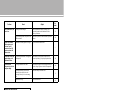
GT-2000/L Turntab le
First CD Player (CD-1) introduced in 1983
B-2x Power Amplifier
MX-10000 Power Amplifier and
CX-10000 Control Amplifier
Redefined the capabilities of separate components.
AX-1 Integrated Amplifier
GT-CD1 CD Player
MX-1 Power Amplifier and
CX-1 Preamplifier
Soavo-1 and Soavo-2 Natural Sound
Speaker Systems
A-S2000 Integrated Amplifier and
CD-S2000 CD Player
NP-S2000 Network Player
A-S3000 Integrated Amplifier and
CD-S3000 CD Player

4 En
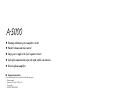
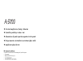
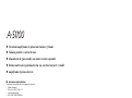
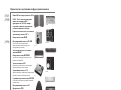
◆ Floating & Balance power amplifier circuit
◆ Parallel volume and tone control
◆ Large power supply with four separate circuits
◆ Left-right symmetrical design with rigid, stable construction
◆ Discrete phono amplifier
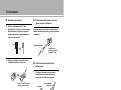
■ Supplied accessories
Please check that you have received all of the following parts.
• Remote control
• Batteries (AAA, R03, UM-4) (×2)
• Power cable
• SAFETY BROCHURE
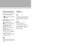
■ About this manual
• y indicates a tip for your operation.
• Photographs and illustrations are for explanatory purposes, and may differ from the actual unit.
• Read the “SAFETY BROCHURE” before using this unit.
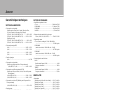
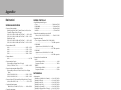
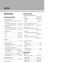
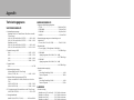
Contents
Controls and functions.......................................................................................................................................... 6
Connections.......................................................................................................................................................... 16
Appendix. ............................................................................................................................................................. 24
Troubleshooting. ............................................................................................................................................... 28

5 En
Controls and
functions
In this chapter, you will learn the controls and functions of A-S1100.

CONTROLS AND FUNCTIONS
6 En
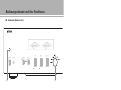
Controls and functions
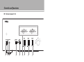
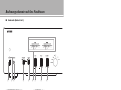
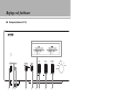
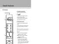
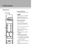
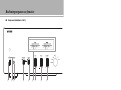
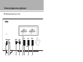
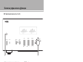
■ Front panel (pages 6 to 9)
1 STANDBY/ON, OFF switch
Turns on or off this unit.
STANDBY/ON (upper position): With this switch
position, pressing the p AMP key on the remote
control toggles the power between STANDBY and
ON.
OFF (lower position): The power of this unit is
turned off.
• When you turn on this unit, it will take a few seconds
before this unit can reproduce sound.
• If you disconnect the power cable from the AC outlet and
connect it again when this unit is in STANDBY mode, the
power of the unit is turned on. If the unit is not to be
operated for a long time, set the STANDBY/ON, OFF
switch to OFF.
2 STANDBY/ON indicator
Lit brightly: Shows that the power of the unit is ON.
Lit dimly: Shows that the unit is in STANDBY mode.
Off: Shows that the power of the unit is OFF.
3 PHONES jack
Connects your headphones.
• When headphones are plugged in:
– Both speaker sets connected to the SPEAKERS L/R CH
terminals are turned off.
– No signals are output at the PRE OUT jacks.
– You cannot select MAIN DIRECT as the input source.
• If headphones are plugged into the PHONES jack while
MAIN DIRECT is selected as the input source, no audio is
output at the PHONES jack.
123
4567 8 9
Notes
Notes

7 En
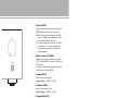
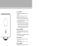
4 SPEAKERS selector
Turns on or off the sets of speakers connected to the
SPEAKERS L/R CH A and/or B terminals on the rear
panel, as follows.
OFF: Both sets of speakers are off.
A/B: The set of speakers connected to the A or B
terminals is on.
A+B BI-WIRING: Both sets of speakers are on.
If you use two sets (A and B), the impedance of each speaker
must be 8 or higher.
5 METER selector
Switches the meter function as follows:
OFF: Turns off the meter and the illumination.
PEAK: The meter functions as a peak level meter.
The peak level meter shows a momentarily highest
audio output level.
VU: The meter functions as a VU (Volume Unit) level
meter. The VU level meter shows an effective
audio output value that is similar to human senses.
6 Meters (LEFT/RIGHT)
Show the audio output level of the left (LEFT) and
right (RIGHT) channels in VU or PEAK meter mode.
The VU or PEAK meter can be selected by the
METER selector.
7 BASS control
Adjusts the volume level of the bass range.
Control range: –10 dB to 0 to +10 dB
8 TREBLE control
Adjusts the volume level of the treble range.
Control range: –10 dB to 0 to +10 dB
9 BALANCE control
Adjusts the audio output balance of the left and right
speakers to compensate for sound imbalances caused
by speaker locations or listening room conditions.
• When both the BASS and TREBLE controls are set to the 0
position, audio signal bypasses the tone control circuitry.
• Adjusting the BASS, TREBLE, and BALANCE controls does
not affect input signals at the MAIN IN jack and output signals
at the LINE 2 REC jack.
Caution
Notes
English

8 En
Controls and functions
■ Front panel (pages 6 to 9)
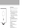
0 Remote control sensor
Receives signals from the remote control.
A INPUT selector/indicator
Selects the input source. The indicator of the input
source selected with the INPUT selector lights. The
audio signals of the selected input source are also
output at the LINE 2 REC jacks.
MAIN DIRECT: Selects the component connected to
the MAIN IN jacks. When MAIN DIRECT is
selected as the input source, the audio signals are
not output at the PRE OUT, LINE 2 REC and
PHONES jacks.
LINE 1/LINE 2: Selects the component connected to
the LINE 1 or LINE 2 jacks.
CD: Selects the CD player connected to the CD jacks.
TUNER: Selects the tuner connected to the TUNER
jacks.
PHONO: Selects the turntable connected to the
PHONO jacks.
When LINE 2 is selected, the audio signals are not output at
the LINE 2 REC jacks.
0
A
Note

9 En
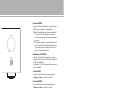
B AUDIO MUTE switch
Press downward to reduce the current volume level by
approximately 20 dB. Press again to restore the audio
output to the previous volume level.
y
You can also rotate the VOLUME control on the front panel
or press the VOLUME + or – key on the remote control to
resume the audio output.
C AUDIO MUTE indicator
Lights when the mute function is turned on with the
AUDIO MUTE switch.
D VOLUME control
Controls the volume level. This does not affect the
output level at the LINE 2 REC jacks.
The VOLUME control does not affect when you select
MAIN DIRECT as the input source. Adjust the volume level
using the volume control on the external amplifier connected
to the MAIN IN jacks.
C D
B
Note
English

10 En
Controls and functions
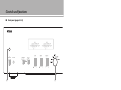
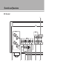
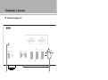
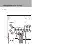
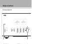
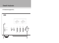
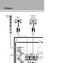
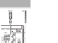
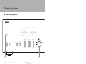
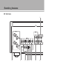
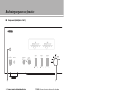
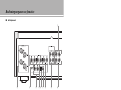
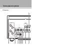
■ Rear panel
1 PRE OUT jacks
y
• The PRE OUT jacks output the same channel signal as the
SPEAKERS L/R CH terminals.
• When you connect a stereo cable to the PRE OUT jacks to
drive the speakers using an external amplifier, it is not
necessary to use the SPEAKERS L/R CH terminals.
• The signal output at the PRE OUT jacks are affected by the
BASS and TREBLE control settings.
2 SPEAKERS L/R CH terminals
3 TUNER input jacks
4 PHONO input jacks
5 CD input jacks
6 MM/MC switch
Selects the type of cartridge of the turntable connected
to the PHONO jacks.
MM: Choose this setting if the connected turntable
uses an moving magnet (MM) cartridge.
MC: Choose this setting if the connected turntable
uses an moving coil (MC) cartridge.
y
When you replace the cartridge, be sure to turn off this unit.
7 GND (Ground) terminal
8 LINE 1 input jacks
9 LINE 2 jacks
PB (playback) input jacks and REC (recording) output
jacks are provided.
2 4768590
1
3
See page 16 for connection information.

11 En
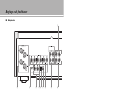
0 MAIN IN jacks
Use these jacks to connect an external component
equipped with a volume control.
y
When you select MAIN DIRECT as the input source, the
volume level is fixed.
Adjust the volume level using the volume control on the
external amplifier connected to the MAIN IN jacks when you
select MAIN DIRECT as the input source.
For the connection to the
MAIN IN
jacks, see pages 16 and 17.
A AUTO POWER STANDBY switch
ON: The unit enters STANDBY mode automatically
if not operated for 8 hours.
OFF: The unit does not enter STANDBY mode
automatically.
B TRIGGER IN jack
Use this jack to connect an external component for the
trigger function.
For details on the connection, see page 21.
C REMOTE IN/OUT jacks
Use these jacks to connect an external component for
remote control.
For details on the connection, see page 20.
D SYSTEM CONNECTOR
Use this connector to connect a product testing device
for servicing.
E AC IN inlet
Use this inlet to plug in the supplied power cable.
For details on the connection, see page 19.
F Foot
If this unit is unstable, you can adjust the foot height
by rotating it.
E2F
ABCD
English

12 En
Controls and functions
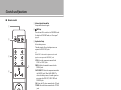
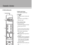
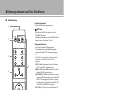
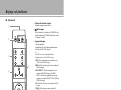
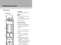
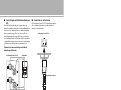
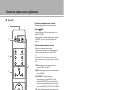
■ Remote control
1 Infrared signal transmitter
Outputs infrared control signals.
2 p AMP key
Turns this unit ON or switches it to STANDBY mode.
For details on STANDBY mode, see “Front panel”
(page 6).
3 Input select keys
Selects the input source.
The audio signals of the selected input source are
output at the LINE 2 REC jacks.
y
When LINE 2 is selected as the input source, the audio
signals are not output at the LINE 2 REC jacks.
LINE: Selects the component connected to the
LINE 1 or LINE 2 jacks.
PHONO: Selects the turntable connected to the
PHONO jacks.
MAIN DIRECT: Selects the component connected to
the MAIN IN jacks. When MAIN DIRECT is
selected as the input source, the audio signals are
not output at the PRE OUT, LINE 2 REC and
PHONES jacks.
CD: Selects the CD player connected to the CD jacks.
TUNER: Selects the tuner connected to the TUNER
jacks.
4 Tuner control buttons
Control functions of Yamaha tuner. Refer to the
owner’s manual of your tuner for details.
Certain Yamaha tuners may not respond to some of these
control keys on the remote control.
4
2
1
3
6
7
AMP CD
OPEN/CLOSE
LINE LINE
PRESET
12
PHONO
MAIN DIRECT
CD TUNER
BAND
MUTE
SOURCE LAYER
VOLUME
5
Note

13 En
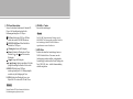
5 CD player control keys
Control various functions of Yamaha CD player. Refer
to the owner’s manual of your CD player for details.
p CD key: Turns the CD player ON or switches it to
STANDBY mode.
OPEN/CLOSE key: Opens/closes the disc tray of
the CD player.
(Play): Starts playback.
(Pause): Pauses playback. Press the or to
resume playback.
(Stop): Stops playback.
/ (Skip): Skips to the next track, or skips
back to the beginning of the current track.
SOURCE: Selects the source to be played on the CD
player. The playback source changes each time this
key is pressed.
LAYER: Switches the playback layer of a hybrid SA-
CD between SA-CD and CD.
Certain Yamaha CD players may not respond to some of
these control keys on the remote control.
6 VOLUME +/– keys
Control the volume level.
The VOLUME keys do not affect when you select MAIN
DIRECT as the input source. Adjust the volume level on the
external amplifier connected to the MAIN IN jacks.
7 MUTE key
Reduces the current volume level by approximately
20 dB. Press again to restore the audio output to the
previous volume level. Pressing the VOLUME + or –
key also cancels muting.
Note
Note
English

14 En
Controls and functions
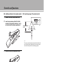
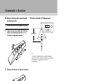
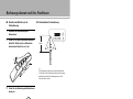
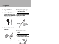
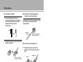
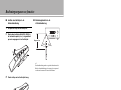
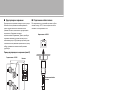
■ Installing batteries in the remote control
1 Remove the battery compartment cover.
2 Insert the two batteries (AAA, R03, UM-4)
according to the polarity markings (+ and –)
on the inside of the battery compartment.
3 Reinstall the battery compartment cover.
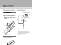
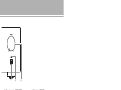
■ Operating range of the remote control
y
The remote control transmits a directional infrared beam. Be
sure to aim the remote control directly at the remote control
sensor on the front panel of this unit during operation.
2
1
3
30 30
Approximately 6 m
(20 ft)

Connections
In this section, you will make connections between A-S1100, speakers,
and source components.

16 En
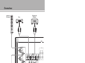
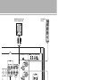
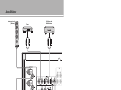
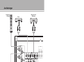
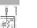
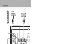
Connections
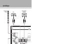
• Do not let the bare speaker wires touch each other or do not let
them touch any metal part of this unit. This could damage this
unit and/or the speakers.
• All connections must be correct: L (left) to L, R (right) to R,
“+” to “+”, and “–” to “–”. If the connections are faulty, no
sound will be heard from the speakers, and if the polarity of the
speaker connections is incorrect, the sound will be unnatural
and lack bass. Also, refer to the owner’s manual for each of
your components.
• Use RCA unbalanced cables to connect other components
except speakers.
• Connect your turntable to the GND terminal to reduce noise in
the signal. However, you may hear less noise without the
connection to the GND terminal for some turntables.
Notes
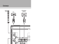
+
-
+
-
CD player with
RCA jacks
Speakers A
(R channel)
Speakers B
(R channel)
Turntable
Ground
Tuner
BD player, etc.

17 En
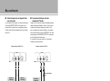
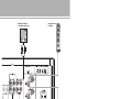
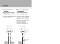
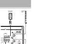
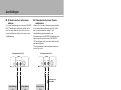
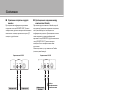
• Because the power amplifier of A-S1100 is of the floating balanced type, the
following types of connections are not possible.
– Connecting with the left channel “–” terminal and the right channel “–” terminal
as well as “+” terminals (Fig. 1).
– Connecting with the left channel “–” terminal and the right channel “–” terminal
inverted (cross connection, Fig. 2).
– Deliberately connecting with the left/right channel “–” terminals and metal part
on the rear panel of this unit, as well as accidentally touching them.
• Do not connect your active subwoofer to the SPEAKERS L/R CH terminal.
Connect it to the PRE OUT jacks.
• Do not connect a component with no volume control, such as a CD player, to the
MAIN IN jacks, as the volume level of the signals input to the MAIN IN jacks is
fixed. If such equipment is connected, a sound may burst, and the unit and/or
speaker may be damaged.
Notes
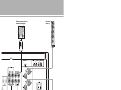
+–
+
-
CD recorder,
tape deck, etc.
Speakers A
(L channel)
Speakers B
(L channel)
External amplifier or
active subwoofer
Preamplifier,
AV receiver, etc.
English
+
–
+
–
L
R
+
–
+
–
L
R
+
–
+
–
L
R
+
–
+
–
L
R
Fig. 1 Fig. 2

18 En
Connections
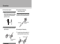
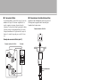
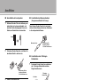
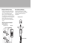
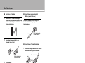
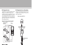
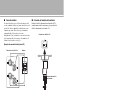
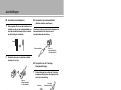
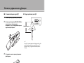
■ Connecting the speakers
1 Remove approximately 10 mm of insulation
from the end of each speaker cable and twist
the exposed wires of the cable together to
prevent short circuits.
2 Unscrew the knob and then insert the bare
wire into the hole.
3 Tighten the knob.
When loosening the knob of the speaker terminal, do not rotate it
excessively. The knob may come off and pose the danger of being
swallowed by a child.
• Touching the speaker terminal with a metallic rack may cause
short circuit and damage this unit. When installing the unit in a
rack, maintain a sufficient clearance to prevent the speaker
terminals from touching the rack.
• To reduce the risk of electric shock, do not touch the speaker
terminal when the unit is turned on.
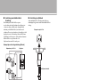
■ Connecting the banana plug
(Except for Europe models)
First, tighten the knob and then insert the banana
plug into the end of the corresponding terminal.
■ Connecting the Y-shaped lug
1 Unscrew the knob and then sandwich the Y-
shaped lug between the ring part and base.
2 Tighten the knob.
Caution
Notes
10 mm
Hole for speaker cable:
6.0 mm dia.
Banana plug
Hole for banana plug:
3.95 mm dia.
Y-shaped lug
Slide
Terminal screw for Y-shaped
lug: 5.8 mm dia.

19 En
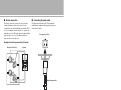
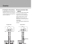
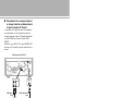
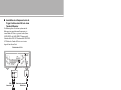
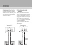
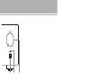
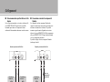
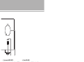
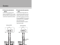
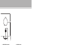
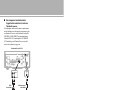
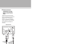
■ Bi-wire connection
The bi-wire connection separates the woofer from the
combined midrange and tweeter section. A bi-wire
compatible speaker has four binding post terminals. These
two sets of terminals allow the speaker to be split into two
independent sections. This split connects the mid and high
frequency drivers to one set of terminals and the low
frequency driver to the other pair.
Example of a bi-wiring connection (R channel)
To use the bi-wire connections, the impedance of each speaker
must be 8 or higher.
Remove the shorting bars or bridges to separate the LPF (low
pass filter) and HPF (high pass filter) crossovers.
y
To use the bi-wire connections, switch the SPEAKERS selector
on the front panel to the A+B BI-WIRING position.
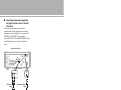
■ Connecting the power cable
Plug the power cable into the AC IN inlet when all
connections are complete, and then plug in the power
cable to the AC outlet.
Caution
Note
SPEAKERS R CH
A
B
+
+
Rear panel of A-S1100 Speaker
to an AC outlet
Rear panel of A-S1100
Supplied power cable
English

20 En
Connections
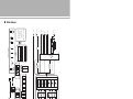
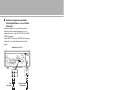
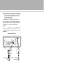
■ Operating this unit from another room
If you connect an infrared receiver and transmitter to the
REMOTE IN/OUT jacks of this unit, you can operate the
unit and/or external component using the supplied remote
control located in another room.
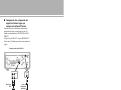
■ Remote connection between Yamaha
components
When you have another Yamaha component supporting
remote connection, as this unit does, an infrared
transmitter is not necessary. You can transmit remote
signals by connecting an infrared receiver and the
REMOTE IN jack of the other component to the
REMOTE IN/OUT jacks of this unit, using cables with
monaural miniplugs.
Up to three Yamaha components (including this unit) can
be connected.
TRIGGER
REMOTE
SYSTEM CONNECTOR
IN IN OUT
Rear panel of A-S1100
Infrared receiver
Remote control
Infrared transmitter
External component
(CD player, etc.)
TRIGGER
REMOTE
SYSTEM CONNECTOR
IN IN OUT
REMOTE
IN OUT
Rear panel of A-S1100
Infrared receiver
Remote control Yamaha component
(up to three
components
including this unit)
Monaural mini-plug
cable
La page charge ...
La page charge ...
La page charge ...
La page charge ...
La page charge ...
La page charge ...
La page charge ...
La page charge ...
La page charge ...
La page charge ...
La page charge ...
La page charge ...
La page charge ...
La page charge ...
La page charge ...
La page charge ...
La page charge ...
La page charge ...
La page charge ...
La page charge ...
La page charge ...
La page charge ...
La page charge ...
La page charge ...
La page charge ...
La page charge ...
La page charge ...
La page charge ...
La page charge ...
La page charge ...
La page charge ...
La page charge ...
La page charge ...
La page charge ...
La page charge ...
La page charge ...
La page charge ...
La page charge ...
La page charge ...
La page charge ...
La page charge ...
La page charge ...
La page charge ...
La page charge ...
La page charge ...
La page charge ...
La page charge ...
La page charge ...
La page charge ...
La page charge ...
La page charge ...
La page charge ...
La page charge ...
La page charge ...
La page charge ...
La page charge ...
La page charge ...
La page charge ...
La page charge ...
La page charge ...
La page charge ...
La page charge ...
La page charge ...
La page charge ...
La page charge ...
La page charge ...
La page charge ...
La page charge ...
La page charge ...
La page charge ...
La page charge ...
La page charge ...
La page charge ...
La page charge ...
La page charge ...
La page charge ...
La page charge ...
La page charge ...
La page charge ...
La page charge ...
La page charge ...
La page charge ...
La page charge ...
La page charge ...
La page charge ...
La page charge ...
La page charge ...
La page charge ...
La page charge ...
La page charge ...
La page charge ...
La page charge ...
La page charge ...
La page charge ...
La page charge ...
La page charge ...
La page charge ...
La page charge ...
La page charge ...
La page charge ...
La page charge ...
La page charge ...
La page charge ...
La page charge ...
La page charge ...
La page charge ...
La page charge ...
La page charge ...
La page charge ...
La page charge ...
La page charge ...
La page charge ...
La page charge ...
La page charge ...
La page charge ...
La page charge ...
La page charge ...
La page charge ...
La page charge ...
La page charge ...
La page charge ...
La page charge ...
La page charge ...
La page charge ...
La page charge ...
La page charge ...
La page charge ...
La page charge ...
La page charge ...
La page charge ...
La page charge ...
La page charge ...
La page charge ...
La page charge ...
La page charge ...
La page charge ...
La page charge ...
La page charge ...
La page charge ...
La page charge ...
La page charge ...
La page charge ...
La page charge ...
La page charge ...
La page charge ...
La page charge ...
La page charge ...
La page charge ...
La page charge ...
La page charge ...
La page charge ...
La page charge ...
La page charge ...
La page charge ...
La page charge ...
La page charge ...
La page charge ...
La page charge ...
La page charge ...
La page charge ...
La page charge ...
La page charge ...
La page charge ...
La page charge ...
La page charge ...
La page charge ...
La page charge ...
La page charge ...
La page charge ...
La page charge ...
La page charge ...
La page charge ...
La page charge ...
La page charge ...
La page charge ...
La page charge ...
La page charge ...
La page charge ...
La page charge ...
La page charge ...
La page charge ...
La page charge ...
La page charge ...
La page charge ...
La page charge ...
La page charge ...
La page charge ...
La page charge ...
La page charge ...
La page charge ...
La page charge ...
La page charge ...
La page charge ...
La page charge ...
La page charge ...
La page charge ...
La page charge ...
La page charge ...
La page charge ...
La page charge ...
La page charge ...
La page charge ...
La page charge ...
La page charge ...
La page charge ...
La page charge ...
La page charge ...
La page charge ...
-
 1
1
-
 2
2
-
 3
3
-
 4
4
-
 5
5
-
 6
6
-
 7
7
-
 8
8
-
 9
9
-
 10
10
-
 11
11
-
 12
12
-
 13
13
-
 14
14
-
 15
15
-
 16
16
-
 17
17
-
 18
18
-
 19
19
-
 20
20
-
 21
21
-
 22
22
-
 23
23
-
 24
24
-
 25
25
-
 26
26
-
 27
27
-
 28
28
-
 29
29
-
 30
30
-
 31
31
-
 32
32
-
 33
33
-
 34
34
-
 35
35
-
 36
36
-
 37
37
-
 38
38
-
 39
39
-
 40
40
-
 41
41
-
 42
42
-
 43
43
-
 44
44
-
 45
45
-
 46
46
-
 47
47
-
 48
48
-
 49
49
-
 50
50
-
 51
51
-
 52
52
-
 53
53
-
 54
54
-
 55
55
-
 56
56
-
 57
57
-
 58
58
-
 59
59
-
 60
60
-
 61
61
-
 62
62
-
 63
63
-
 64
64
-
 65
65
-
 66
66
-
 67
67
-
 68
68
-
 69
69
-
 70
70
-
 71
71
-
 72
72
-
 73
73
-
 74
74
-
 75
75
-
 76
76
-
 77
77
-
 78
78
-
 79
79
-
 80
80
-
 81
81
-
 82
82
-
 83
83
-
 84
84
-
 85
85
-
 86
86
-
 87
87
-
 88
88
-
 89
89
-
 90
90
-
 91
91
-
 92
92
-
 93
93
-
 94
94
-
 95
95
-
 96
96
-
 97
97
-
 98
98
-
 99
99
-
 100
100
-
 101
101
-
 102
102
-
 103
103
-
 104
104
-
 105
105
-
 106
106
-
 107
107
-
 108
108
-
 109
109
-
 110
110
-
 111
111
-
 112
112
-
 113
113
-
 114
114
-
 115
115
-
 116
116
-
 117
117
-
 118
118
-
 119
119
-
 120
120
-
 121
121
-
 122
122
-
 123
123
-
 124
124
-
 125
125
-
 126
126
-
 127
127
-
 128
128
-
 129
129
-
 130
130
-
 131
131
-
 132
132
-
 133
133
-
 134
134
-
 135
135
-
 136
136
-
 137
137
-
 138
138
-
 139
139
-
 140
140
-
 141
141
-
 142
142
-
 143
143
-
 144
144
-
 145
145
-
 146
146
-
 147
147
-
 148
148
-
 149
149
-
 150
150
-
 151
151
-
 152
152
-
 153
153
-
 154
154
-
 155
155
-
 156
156
-
 157
157
-
 158
158
-
 159
159
-
 160
160
-
 161
161
-
 162
162
-
 163
163
-
 164
164
-
 165
165
-
 166
166
-
 167
167
-
 168
168
-
 169
169
-
 170
170
-
 171
171
-
 172
172
-
 173
173
-
 174
174
-
 175
175
-
 176
176
-
 177
177
-
 178
178
-
 179
179
-
 180
180
-
 181
181
-
 182
182
-
 183
183
-
 184
184
-
 185
185
-
 186
186
-
 187
187
-
 188
188
-
 189
189
-
 190
190
-
 191
191
-
 192
192
-
 193
193
-
 194
194
-
 195
195
-
 196
196
-
 197
197
-
 198
198
-
 199
199
-
 200
200
-
 201
201
-
 202
202
-
 203
203
-
 204
204
-
 205
205
-
 206
206
-
 207
207
-
 208
208
-
 209
209
-
 210
210
-
 211
211
-
 212
212
-
 213
213
-
 214
214
-
 215
215
-
 216
216
-
 217
217
-
 218
218
-
 219
219
-
 220
220
-
 221
221
-
 222
222
-
 223
223
-
 224
224
-
 225
225
-
 226
226
-
 227
227
-
 228
228


Yamaha A-S1100 Silver/Piano Black Manuel utilisateur
- Catégorie
- Amplificateur d'instruments de musique
- Taper
- Manuel utilisateur
dans d''autres langues
Documents connexes
-
Yamaha A-S1100 Le manuel du propriétaire
-
-
Yamaha A-S3000 Le manuel du propriétaire
-
Yamaha A-S2100BL Manuel utilisateur
-
-
-
Yamaha A-S2200 Le manuel du propriétaire
-