
READ AND FOLLOW ALL SAFETY INSTRUCTIONS! SAVE THESE
INSTRUCTIONS AND DELIVER TO OWNER AFTER INSTALLATION
• To reduce the risk of death, personal injury or property damage from fire, electric
shock, falling parts, cuts/abrasions, and other hazards please read all warnings
and instructions included with and on the fixture box and all fixture labels.
• Before installing, servicing, or performing routine maintenance upon this
equipment, follow these general precautions.
• Installation and service of luminaires should be performed by a qualified
licensed electrician.
• Maintenance of the luminaires should be performed by person(s) familiar
with the luminaires’ construction and operation and any hazards involved.
Regular fixture maintenance programs are recommended.
• It will occasionally be necessary to clean the outside of the refractor/lens.
Frequency of cleaning will depend on ambient dirt level and minimum light
output which is acceptable to user. Refractor/lens should be washed in a
solution of warm water and any mild, non-abrasive household detergent,
rinsed with clean water and wiped dry. Should optical assembly become
dirty on the inside, wipe refractor/lens and clean in above manner, replacing
damaged gaskets as necessary.
• DO NOT INSTALL DAMAGED PRODUCT! This luminaire has been properly
packed so that no parts should have been damaged during transit. Inspect to
confirm. Any part damaged or broken during or after assembly should be replaced.
• Recycle: For information on how to recycle LED electronic products, please
visit www.epa.gov.
• These instructions do not purport to cover all details or variations in
equipment nor to provide every possible contingency to meet in connection
with installation, operation, or maintenance. Should further information
be desired or should particular problems arise which are not covered
sufficiently for the purchaser’s or owner’s purposes, this matter should be
referred to Acuity Brands Lighting, Inc.
• Disconnect or turn off power before installation or servicing.
• Verify that supply voltage is correct by comparing it with the luminaire label
information.
• Make all electrical and grounded connections in accordance with the
National Electrical Code (NEC) and any applicable local code requirements.
• All wiring connections should be capped with UL approved recognized wire
connectors.
• Wear gloves and safety glasses at all times when removing luminaire from
carton, installing, servicing or performing maintenance.
• Avoid direct eye exposure to the light source while it is on.
WARNING RISK OF BURN
• Allow lamp/fixture to cool before handling. Do not touch enclosure or light source.
• Do not exceed maximum wattage marked on luminaire label.
• Follow all manufacturer’s warnings, recommendations and restrictions for: driver
type, burning position, mounting locations/methods, replacement and recycling.
CAUTION RISK OF FIRE
• Keep combustible and other materials that can burn, away from lamp/lens.
• Do not operate in close proximity to persons, combustible materials or
substances affected by heat or drying.
CAUTION: RISK OF PRODUCT DAMAGE
• Never connect components under load.
• Do not mount or support these fixtures in a manner that can cut the outer
jacket or damage wire insulation.
• Unless individual product specifications deem otherwise: Never connect an LED
product to dimmer packs, occupancy sensors, timing devices, or other related
control devices. LED fixtures must be powered directly off a switched circuit.
• Unless individual product specifications deem otherwise: Do not restrict
fixture ventilation. Allow for some volume of airspace around fixture. Avoid
covering LED fixtures with insulation, foam, or other material that will
prevent convection or conduction cooling.
• Unless individual product specifications deem otherwise: Do not exceed
fixtures maximum ambient temperature.
• Only use fixture in its intended location.
• LED products are Polarity Sensitive. Ensure proper Polarity before installation.
• Electrostatic Discharge (ESD): ESD can damage LED fixtures. Personal
grounding equipment must be worn during all installation or servicing of the unit.
• Do not touch individual electrical components as this can cause ESD,
shorten lamp life, or alter performance.
• Some components inside the fixture may not be serviceable. In the unlikely
event your unit may require service, stop using the unit immediately and
contact an ABL representative for assistance.
• Always read the fixtures complete installation instructions prior to installation
for any additional fixture specific warnings.
• Verify that power distribution system has proper grounding. Lack of proper
earth ground can lead to fixture failure and may void warranty.
All luminaires that contain electronic devices that generate frequencies
above 9kHz from any component within the luminaire comply with
Part 15 of the FCC Rules. Operation is subject to the following two
conditions: (1) This device may not cause harmful interference (2) This
device must accept any interference received, including interference that
may cause undesired operation.
Failure to follow any of these instructions could void product warranties.
For a complete listing of product Terms and Conditions, please visit
www.acuitybrands.com. Acuity Brands Lighting, Inc. assumes no
responsibility for claims arising out of improper or careless installation or
handling of its products.
ABL LED General Warnings, Form No. 503.203
© 2010 Acuity Brands Lighting, Inc. All rights reserved. 12/01/10
LEA Y RESPETE TODAS LAS INSTRUCCIONES DE INSTALACIÓN
GUARDE LAS INSTRUCCIONES Y DEVUÉLVALAS AL PROPIETARIO
DESPUÉS DE REALIZAR LA INSTALACIÓN
• Para reducir el riesgo de muerte, lesiones personales o daño a la propiedad que
pueda surgir de incendios, choques eléctricos, cortes, abrasiones, caída de
partes y otros peligros lea todas las advertencias e instrucciones incluidas en
la caja o su interior, además de las etiquetas del montaje.
• Antes de instalar, revisar o realizar el mantenimiento de rutina del equipo, siga
estas precauciones generales.
• La instalación y el mantenimiento de las luminarias lo debe realizar un electri-
cista calificado autorizado.
• El mantenimiento de las luminarias lo debe realizar una persona familiarizada con la
fabricación y el funcionamiento de este producto así como con los peligros relacio-
nados con este. Se recomienda realizar el mantenimiento regular de los montajes.
• Cada tanto será necesario limpiar la parte externa del refractor y de la lente. La
frecuencia de la limpieza dependerá del nivel de polvo del ambiente y de la potencia
de la luz mínima aceptable para el usuario. El refractor/la lente se debe lavar con una
solución de agua tibia y detergente de uso doméstico suave no abrasivo, enjuagar con
agua limpia y secar. Si el montaje óptico se ensuciara por dentro, limpie el refractor o la
lente como se indicó anteriormente; de ser necesario, reemplace las juntas dañadas.
• NO INSTALE EL PRODUCTO SI ESTÁ DAÑADO Esta luminaria se embaló
adecuadamente de modo tal que las piezas no resulten dañadas durante su
transporte. Inspecciónelas para confirmarlo. Reemplace toda pieza que se
dañe o rompa durante su montaje o posterior a este.
• Reciclado: Para obtener información sobre cómo reciclar productos electrónic-
os LED, visite www.epa.gov.
• Estas instrucciones no pretenden cubrir todos los detalles o las variaciones de
los equipos ni abarcar todas las posibles eventualidades relacionadas con la
instalación, el funcionamiento o el mantenimiento. Si necesita más información
o surgen problemas específi cos que no están debidamente cubiertos en la
información del producto, remítase a Acuity Brands Lighting, Inc.
• Desconecte o interrumpa la energía eléctrica antes de realizar la instalación o
la reparación.
• Verifi que el voltaje de alimentación sea correcto; compárelo con la información
de la etiqueta de la luminaria.
• Realice todas las conexiones eléctricas y a tierra en cumplimiento con el
Código Eléctrico Nacional y de los requisitos del código local vigente.
• Todas las conexiones de cableado deben cubrirse con conectores para cable
reconocidos y aprobados por UL.
• Use gafas y guantes de protección en todo momento al retirar la luminaria de la
caja, al instalarla, repararla o realizar operaciones de mantenimiento.
• Una vez encendida la fuente de luz, evite la exposición directa con los ojos.
ADVERTENCIA: RIESGO DE QUEMADURAS
• Antes de manipular la lámpara o el montaje, déjelo enfriar. No toque la carcasa
ni la fuente de iluminación.
• No supere el voltaje máximo señalado en la etiqueta de la luminaria.
• Respete todas las advertencias, recomendaciones y restricciones que propor-
ciona el fabricante para: tipo de conductor, posición de funcionamiento, puntos
o métodos de montaje, reemplazo y reciclado.
PRECAUCIÓN: RIESGO DE INCENDIO
• Mantenga lejos de la luminaria y de las lámparas o los lentes, los materiales
combustibles y de otro tipo que se puedan incendiar.
• No las encienda cerca de personas, materiales combustibles o sustancias
calientes o secas.
• Jamás conecte componentes bajo carga.
• No monte estos montajes de manera que puedan cortar el revestimiento
exterior o dañar el aislamiento de los cables.
• A menos que las especifi caciones del producto individual consideren lo
contrario: Jamás conecte un producto LED directamente a un paquete de
reducción de intensidad de la luz, sensores de ocupación, dispositivos de
sincronización u otros dispositivos de control relacionados. Los montajes LED
se deben apagar directamente de un circuito de interruptores.
• A menos que las especifi caciones del producto individual consideren lo
contrario: No restrinja la ventilación de las luminarias. Deje un poco de espacio
alrededor del montaje. Evite cubrir los montajes LED con aislación, goma u otro
material que evitará la convección o el enfriamiento de la conducción.
• A menos que las especifi caciones del producto individual consideren lo con-
trario: No exceda la temperatura ambiente máxima de las luminarias.
• Use la luminaria únicamente en el lugar previsto.
• Los productos LED son sensibles a la polaridad. Asegure la correcta polaridad
antes de la instalación.
• Descarga electrostática (DES): la DES puede dañar los montajes LED. Durante la
instalación o reparación de la unidad se debe usar siempre equipo personal
conectado a tierra.
• No toque componentes eléctricos individuales ya que esto puede causar DES,
reducir la vida útil de la lámpara o alterar el funcionamiento.
• Es posible que algunos componentes dentro del montaje no se puedan reparar. En
el caso improbable de que su unidad requiera reparación, deje de usar la unidad
inmediatamente y comuníquese con un representante de ABL para obtener ayuda.
• Lea siempre las instrucciones completas de instalación de montaje antes de la
instalación para verificar si hay advertencias específicas de montaje adicionales.
• Verifique que el sistema de distribución de alimentación tenga una conexión a
tierra adecuada. La falta de una toma de tierra adecuada puede conducir a una
falla de la luminaria y puede anular la garantía.
Todas las luminarias que contienen dispositivos eléctricos que
generan frecuencias superiores a 9 kHz desde cualquier componente
de la luminaria cumplen con la Parte 15 de las reglas de la FCC. El
funcionamiento está sujeto a las siguientes dos condiciones: (1) este
dispositivo no puede ocasionar interferencias perjudiciales, y (2) este
dispositivo debe aceptar cualquier interferencia recibida, incluso
aquellas que pueden ocasionar un mal funcionamiento.
El incumplimiento de alguna de estas instrucciones puede anular la garantía
del producto. Para obtener la lista completa de los términos y las condiciones
respecto del producto, visite www.acuitybrands.com. Acuity Brands Lighting,
Inc. no se hace responsable por los reclamos que puedan surgir de la
instalación o manipulación inadecuada o negligente de sus productos.
Advertencias generales de ABL LED, Form. no. 503.203
© 2010 Acuity Brands Lighting, Inc. Todos los derechos reservados. 12/01/10
LIRE ATTENTIVEMENT ET OBSERVER TOUTES LES CONSIGNES DE
SÉCURITÉ CONSERVER CES DIRECTIVES ET LES REMETTRE AU
PROPRIÉTAIRE APRÈS L’INSTALLATION
• Pour réduire les risques de décès, blessures ou dommages matériels résultant
d’un incendie, d’un choc électrique, de chutes de pièces, coupures, érafl ures et
autres dangers, veuillez lire tous les avertissements et toutes les directives fournis
avec l’appareil, sur la boîte et les étiquettes.
• Avant l’installation, l’entretien ou la maintenance de cet équipement, veuillez
prendre les précautions générales suivantes.
• L’installation et le service technique des luminaires doivent être effectués par un
électricien licencié qualifié.
• L’entretien des luminaires doit être effectué par des personnes au courant de la
construction et du fonctionnement des luminaires et des risques impliqués. Un
programme d’entretien régulier est recommandé.
• À l’occasion, il sera nécessaire de nettoyer l’extérieur du réfracteur ou de la lentille.
La fréquence de nettoyage dépendra du niveau de saleté ambiant et du fl ux
lumineux minimal acceptable pour l’utilisateur. Le réfracteur et la lentille doivent être
nettoyés à l’aide d’une solution d’eau tempérée et de tout détergent domestique
doux, non abrasif, puis rincés à l’eau propre et essuyés. En cas de saleté à
l’intérieur du bloc optique, essuyer le réfracteur ou la lentille, puis nettoyer comme
indiqué ci-dessus et remplacer toute garniture d’étanchéité endommagée au besoin.
• NE PAS INSTALLER UN PRODUIT ENDOMMAGÉ ! Ce luminaire a été emballé
de manière à ce que les pièces ne subissent pas de dommages lors du transport.
Veuillez inspecter et confirmer le bon état. Toute pièce endommagée ou brisée
lors de l’assemblage ou après devrait être remplacée.
• Recyclage : pour accéder à l’information sur le recyclage des produits électro-
niques DEL, veuillez visiter www.epa.gov.
• Ces directives n’entendent pas couvrir tous les détails, tous les modèles
d’équipement, ni prévoir toute éventualité liée à l’installation, au fonctionnement
ou à l’entretien de cet équipement. Pour toute autre information ou en cas d’un
problème non résolu par le présent document, l’acheteur ou le propriétaire est prié
de contacter Acuity Brands Lighting, Inc.
• Couper ou éteindre l’alimentation électrique avant l’installation ou l’entretien.
• Vérifi er que la tension d’alimentation est adéquate en la comparant à l’information
sur l’étiquette du luminaire.
• Effectuer toutes les connexions et la mise à la terre conformément au National
Electrical Code (NEC) et aux exigences de tout autre code local applicable.
• Touteslesconnexionsdoiventêtreprotégéesd’uncapuchondeconnexionhomologuéUL.
• Porter des gants et des verres de sécurité en tout temps pour retirer le luminaire de
la boîte, l’installation, l’entretien ou les travaux de maintenance.
• Éviter d’exposer directement les yeux à la source lumineuse lorsqu’allumée.
AVERTISSEMENT RISQUE DE BRÛLURE
• Permettre le refroidissement de la lampe et du luminaire avant la manipulation. Ne
pas toucher au boîtier ou à la source lumineuse.
• Ne pas dépasser la puissance maximale indiquée sur l’étiquette du luminaire.
• Observer tous les avertissements, toutes les recommandations et toutes
les restrictions du fabricant sur : le type de pilote, la position d’utilisation,
l’emplacement et les méthodes de montage, le remplacement et le recyclage.
• Éloigner toutes les matières combustibles ou infl ammables de la lampe et de la lentille.
• Ne pas employer à proximité des personnes, des matières combustibles ou des
substances sensibles à la chaleur ou la sécheresse.
• Ne jamais connecter des composantes en charge.
• Ne pas monter ou supporter ces appareils d’une manière pouvant causer l’abrasion
de la gaine externe ou endommager l’isolant des fils.
• Sauf si contraire aux spécifications du produit individuel : Ne jamais connecter
directement un produit DEL sur un gradateur, un détecteur de présence, un
temporisateur ni sur aucun autre appareil de contrôle de ce type. Les appareils
DEL doivent être alimentés directement hors d’un circuit à interrupteur.
• Sauf en cas de spécifi cations contraires individuelles des produits : Ne pas limiter
la ventilation du luminaire. Permettre un espace libre suffi sant autour du luminaire.
Éviter de couvrir les appareils DEL d’un matériau isolant, alvéolaire ou tout autre
matériau empêchant le refroidissement de l’unité par convexion ou conduction.
• Sauf en cas de spécifi cations contraires individuelles des produits : Ne pas
dépasser la température ambiante maximale de service admissible.
• Utiliser le luminaire qu’à l’endroit prévu à cet effet.
• Les produits DEL sont sensibles à la polarité. S’assurer d’une polarité adéquate
avant l’installation.
• Décharge électrostatique (DES) : Une DES peut endommager les appareils DEL.
Un équipement de mise à la terre de protection individuelle doit être porté lors de
l’installation ou l’entretien de l’unité.
• Ne pas toucher aux composantes électriques individuelles, car cela peut causer une
DES, réduire la durée de vie de la lampe ou compromettre la performance de l’unité.
• Certains composants internes des luminaires peuvent ne pas être réparables.
Dans le cas peu probable où l’appareil aurait besoin d’une réparation,
immédiatement cesser de l’utiliser et faire appel à un représentant ABL.
• Avant de procéder au montage, toujours lire toutes les instructions de montage des
luminaires pour connaître les autres avertissements qui leur sont propres.
• Vérifiez que le système de distribution électrique a une mise à la terre appropriée.
Une mauvaise mise à la terre peut entraîner une défaillance du luminaire et
annuler la garantie.
Tous les luminaires qui contiennent des dispositifs électroniques générant des
fréquences supérieures à 9 kHz à partir d’un composant situé à l’intérieur du
luminaire sont conformes à la section 15 des règles de la Commission fédérale
des communications. Son fonctionnement doit respecter les deux conditions
suivantes : (1) Ce dispositif ne doit générer aucune interférence préjudiciable
(2) Ce dispositif doit accepter n’importe quelle interférence reçue, y compris
les interférences pouvant entraîner un fonctionnement non souhaité.
Ne pas observer ces instructions pourrait annuler les garanties du produit.
Pour une liste complète des conditions et modalités, veuillez visiter
www.acuitybrands.com. Acuity Brands Lighting, Inc. décline toute
responsabilité pour les réclamations résultant d’une installation ou
manipulation inadéquate ou négligente de ses produits.
Avertissements généraux de ABL sur les produits DEL, pub. no 503.203
© 2010 Acuity Brands Lighting, Inc. Tous droits réservés. 12/01/10
IMPORTANTES CONSIGNES DE
SÉCURITÉ SUR L’ÉCLAIRAGE DEL
INSTRUCCIONES DE SEGURIDAD
IMPORTANTES SOBRE EL LED
IMPORTANT SAFETY INSTRUCTIONS
WARNING RISK OF ELECTRIC SHOCK
CAUTION RISK OF INJURY
ADVERTENCIA: RIESGO DE CHOQUE ELÉCTRICO
PRECAUCIÓN: RIESGO DE LESIONES
PRECAUCIÓN: RIESGO DE DAÑO PARA EL PRODUCTO
AVERTISSEMENT RISQUE DE CHOC ÉLECTRIQUE
MISE EN GARDE RISQUE DE BLESSURE
MISE EN GARDE RISQUE D’INCENDIE
MISE EN GARDE : RISQUE DE CAUSER DES DOMMAGES AU PRODUIT

LED Steel Sign
INSTRUCTIONS FOR Lithonia Lighting TCE
READ AND FOLLOW ALL SAFETY INSTRUCTIONS
SAVE THIS INSTRUCTIONS
and deliver to owner after installation
PAGE: 1 of 18
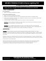
When using electrical equipment, basic safety precautions
should always be followed, including the following:
READ AND FOLLOW ALL SAFETY INSTRUCTIONS
WARNING: FAILURE TO FOLLOW THESE INSTRUCTIONS AND WARNINGS MAY RESULT IN DEATH, SERIOUS INJURY OR
SIGNIFICANT PROPERTY DAMAGE. For your protection, read and follow these warnings and instructions carefully before installing or
maintaining this equipment. These instructions do not attempt to cover all installation and maintenance situations. If you do not understand
these instructions or additional information is required, contact LITHONIA LIGHTING or your local LITHONIA LIGHTING distributor.
WARNING: RISK OF ELECTRIC SHOCK –NEVER CONNECT TO, DISCONNECT FROM, OR SERVICE WHILE EQUIPMENT IS
ENERGIZED.
WARNING: DO NOT USE ABRASIVE MATERIALS OR SOLVENTS. USE OF THESE SUBSTANCES MAY DAMAGE FIXTURE,
WHICH MAY RESULT IN PERSONAL INJURY.
WARNING: RISK OF PERSONAL INJURY –This product may have sharp edges. Wear gloves to prevent cuts or abrasions when removing
from carton, handling, installing and maintaining this product.
WARNING: RISK OF FIRE. Lamps are hot. Keep combustible material away from hot parts. Observe lamp manufacturer’s warnings,
recommendations and restrictions on lamp operation and maintenance. Make sure lamps are correctly installed.
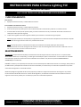
IMPORTANT SAFEGUARDS
•Do not use outdoors. Suitable for use in damp location 32°F –104°F (0°C –40°C).
•Consult local building code for approved wiring and installation.
•Disconnect A.C. power before servicing and installation.
•Do not mount near gas or electric heater.
•Do not use this equipment for other than intended use.
•The use of accessory equipment not recommended by the manufacturer may cause an unsafe condition.
•All servicing on this equipment should be performed by qualified personnel only.
•Equipment should be mounted in locations and at heights where it will not be subject to tampering by
unauthorized personnel.
•Use caution when servicing batteries.
•Make sure wire terminations are secure and leads are properly tucked in appropriate wire channels.
IMPORTANT SAFEGUARDS: When using electrical equipment, basic safety precautions should always be followed,
including the following:

LED Steel Sign
INSTRUCTIONS FOR Lithonia Lighting TCE
READ AND FOLLOW ALL SAFETY INSTRUCTIONS
SAVE THESE INSTRUCTIONS
and deliver to owner after installation
PAGE: 2 of 18
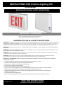
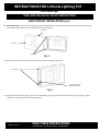
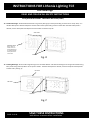
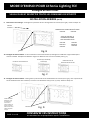
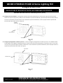
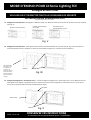
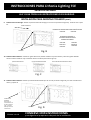
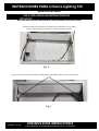
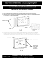
BACK MOUNT INSTALLATION
IMPORTANT: Provide each unit with a single-phase AC un-switched power supply from a circuit used for normal lighting.
“UVOLT” product versions operate from 120 volts through 347 volts. PRODUCT DAMAGE WILL OCCUR IF THE RATED INPUT VOLTAGE IS EXCEEDED.
NOTE: The battery (if applicable) must be connected to the charger board prior to applying AC power to the unit. Battery damage may occur if the battery is connected
longer than 24
hours without continuous AC power provided. See also “Important Battery Information”.
NOTE: Do not connect battery or power unit until remote units (if applicable) are fully connected and wires are isolated from other potentials (i.e. remote wires shall be
isolated from earth ground).
NOTE: Supports 4” Square, 4” Octagon or a single rectangular (4”x 2.125”) J-Box.
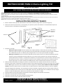
1. Remove the side cover by unscrewing two side screws and remove side cover. (See Fig. A)
2. Slide out front panel, if applicable, to permit installation process. Installer will need to remove bonding screw on Standard
Exit Signs.
3. Mounting options:
•J-Box Mounting: knock out the appropriate mounting pattern and the wire pass hole in the backplate to fit the J-box
being used. Approved J-Box sizes are 4” Square (With or without plaster ring), 4” Octagon, or a single rectangular J-
Box.
•Conduit Mounting: knock out the appropriate conduit and mount the backplate to the wall in the desired location
using the keyhole knockouts (See Fig. A). Attach a conduit hub to desired conduit mount hole on the frame. An
additional screw may be required at the j-box center bottom hole to pull the unit back into the wall as visible from
the bottom of the unit. Do not use center knockout if the EHO battery option is used to prevent interference of the
conduit with the battery.
4. Use code-approved connectors to make the connection inside the unit. Connect the hot wire to the red lead. Connect neutral
wire to the white lead. The ground wire (green lead) needs to be connected in accordance with the local codes. DO NOT
energize the circuit at this time (See Wiring Diagram). For Units with Remote Lamp Wires: Connect remote wires to the
remote output. The yellow wire is the positive remote wire and blue is the negative (See Wiring Diagram). If no remote
lamps are connected, make sure remote wire harness is removed from the unit to prevent shorting. Wires shall be neatly
dressed inside the unit to prevent any shadowing of the exit sign (i.e., routed closely to side of unit).
5. Connect the battery to the main board (if applicable). Refer to the wiring diagram below.
6. Proceed to step 9 for Chicago Sign.
7. Proceed to step 10 and 11 for Standard Exit Sign.
8. Proceed to step 12 for Running Man Sign.
Fig. A
SIDE SCREWS
CONDUIT MOUNT
KNOCKOUTS
KEY HOLES
J-BOX HOLES
SIDE COVER
Standard Exit Sign
BONDING SCREW

LED Steel Sign
INSTRUCTIONS FOR Lithonia Lighting TCE
READ AND FOLLOW ALL SAFETY INSTRUCTIONS
SAVE THESE INSTRUCTIONS
and deliver to owner after installation
PAGE: 3 of 18
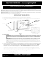
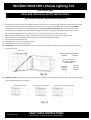
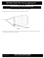
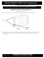
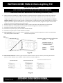
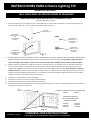
BACK MOUNT INSTALLATION (CONT.)
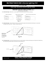
9. Chicago Glass Sign: Slide Chicago Glass Panel into grooves (See Fig B). Proceed to step 13.
10. Standard Exit Sign: If directional chevron is desired slide red diffuser out and knockout desired chevron. Replace red diffuser
or green diffuser if desired. (See Fig C)
11. Standard Exit Sign: Slide Standard Exit Panel into grooves (See Fig D), with Standard Exit Panel facing out, and torque
bonding screw to 10.6 in-lbs. (1.2Nm) Proceed to step 13.
Fig. B
REMOVE RED DIFFUSER
Fig. C
Fig. D
GROOVES
SLIDE PANEL
GROOVES
BONDING SCREW
Note: There is a
similar screw on
the backplate that
if removed should
be torqued to the
same value.
REMOVE DESIRED CHEVRON(S) REPLACE WITH RED OR GREEN DIFFUSER
UL924 CERTIFIED GLASS PANELS
CHP ENA CHP SNA
CITY OF CHICAGO, IL
NON UL924 CERTIFIED
GLASS PANELS
CHP ERA
CHP ELFA
CHP EDA
CHP SRA
CHP SLFA
CHP SDA

LED Steel Sign
INSTRUCTIONS FOR Lithonia Lighting TCE
READ AND FOLLOW ALL SAFETY INSTRUCTIONS
SAVE THESE INSTRUCTIONS
and deliver to owner after installation
PAGE: 4 of 18
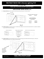
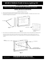
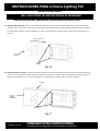
BACK MOUNT INSTALLATION (CONT.)
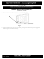
12. Running Man Sign: Place the Running Man sign over the white diffuser and slide stacked signs into the grooves with Running
Man panel facing outward, RM no Arrow panel is shown (See Fig. E).
13. Replace the side cover and torque the side screws to 10.6 in-lbs (1.2Nm) (See Fig F).
14. Energize the unit with AC supply. If the unit includes battery, the charge indicator will illuminate green for charging. Allow
battery to charge for 24 hours before initial testing.
Fig. E
Fig. F
TEST SWITCH AND LED
(EMERGENCY ONLY)
SIDE SCREWS
GROOVES
DIFFUSER
RM PANEL

LED Steel Sign
INSTRUCTIONS FOR Lithonia Lighting TCE
READ AND FOLLOW ALL SAFETY INSTRUCTIONS
SAVE THESE INSTRUCTIONS
and deliver to owner after installation
PAGE: 5 of 18
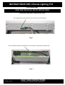
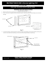
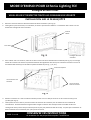
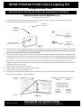
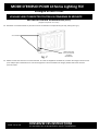
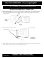
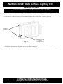
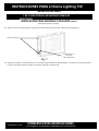
TOP/SIDE MOUNT INSTALLATION
1. Remove the side cover by unscrewing two side screws and remove side cover. (See Fig. G)
2. Slide out front panel, if applicable, to permit installation process. Installer will need to remove bonding screw on Standard
Exit Signs.
3. To use with a canopy, remove the canopy screws and remove the desired knockout (See Fig H). Side canopy mount is shown.
The battery tray will also need be removed to route harness through the desired knockout, then reinstall battery tray (See Fig
I, J, K, and L).
4. Mount the canopy to the unit at the desired location (top or side) and torque the canopy screws to 10.6 in-lbs (1.2Nm) (See
Fig H).
5. Pass the wires through the wall of the unit and canopy cover for routing to the junction box. Wires shall be neatly dressed
inside the unit to prevent any shadowing of the exit sign (i.e., routed closely to side of unit). Installer may need to lower
battery tray to route AC wires through battery tray.
Fig. G
Fig. H
SIDE MOUNT CANOPY SCREWS
TOP SIDE CANOPY SCREWS
KNOCK OUTS
SIDE SCREWS
BACK PANEL
Standard Exit Sign
BONDING SCREW

LED Steel Sign
INSTRUCTIONS FOR Lithonia Lighting TCE
READ AND FOLLOW ALL SAFETY INSTRUCTIONS
SAVE THESE INSTRUCTIONS
and deliver to owner after installation
PAGE: 6 of 18
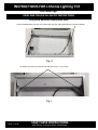
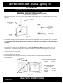
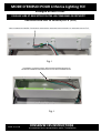
TOP/SIDE MOUNT INSTALLATION :
Fig. I
ROUTE HARNESS THROUGH TOP KNOCKOUT FOR TOP MOUNT THEN REINSTALL POWER TRAY.
PULL HARNESS BACK THROUGH HOLE FOR TOP MOUNT AND SIDE MOUNT
Fig. J

LED Steel Sign
INSTRUCTIONS FOR Lithonia Lighting TCE
READ AND FOLLOW ALL SAFETY INSTRUCTIONS
SAVE THESE INSTRUCTIONS
and deliver to owner after installation
PAGE: 7 of 18
TOP/SIDE MOUNT INSTALLATION :
Fig. K
ROUTE HARNESS INSIDE BATTERY TRAY AND DOWN THE SIDE THROUGH KNOCKOUT FOR SIDE MOUNT
Fig. L
RE-INSTALL BATTERY TRAY SCREWS AND TORQUE TO 10.6 in-lbs (1.2Nm).

LED Steel Sign
INSTRUCTIONS FOR Lithonia Lighting TCE
READ AND FOLLOW ALL SAFETY INSTRUCTIONS
SAVE THESE INSTRUCTIONS
and deliver to owner after installation
PAGE: 8 of 18
6. Use code-approved connectors to make the connection inside the unit. Connect the hot wire to the red lead. Connect neutral
wire to the white lead. The ground wire (green lead) needs to be connected in accordance with the local codes. DO NOT
energize the circuit at this time (See Wiring Diagram). For Units with Remote Lamp Wires: Connect remote wires to the
remote output. The yellow wire is the positive remote wire and blue is the negative (See Wiring Diagram). If no remote
lamps are connected, make sure remote wire harness is removed from the unit to prevent shorting.
7. Mount canopy to the wall if the canopy is mounted on the side or ceiling if the canopy is mounted on the top.
8. Connect the battery (if applicable) to the main board. Refer to the wiring diagram below.
9. Proceed to step 12 for Chicago Sign.
10. Proceed to step 13 and 14 for Standard Exit Sign.
11. Proceed to step 15 for Running Man Sign.
12. Chicago Sign: Slide Chicago Glass Panel into grooves (See Fig M). If a double-sided panel is wanted add panels to both sides.
Proceed to step 16.
13. Standard Exit Sign: If directional chevron is desired slide red diffuser out and knockout desired chevron. Replace red diffuser
or green diffuser if desired. (See Fig N).
TOP/SIDE MOUNT INSTALLATION (CONT.)
Fig. M
GROOVES
SLIDE PANEL
Fig. N
REMOVE RED DIFFUSER REMOVE DESIRED CHEVRON(S) REPLACE WITH RED OR GREEN DIFFUSER
UL924 CERTIFIED GLASS PANELS
CHP ENA CHP SNA
CITY OF CHICAGO, IL
NON UL924 CERTIFIED
GLASS PANELS
CHP ERA
CHP ELFA
CHP EDA
CHP SRA
CHP SLFA
CHP SDA

LED Steel Sign
INSTRUCTIONS FOR Lithonia Lighting TCE
READ AND FOLLOW ALL SAFETY INSTRUCTIONS
SAVE THESE INSTRUCTIONS
and deliver to owner after installation
PAGE: 9 of 18
14. Standard Exit Sign: Slide Standard Exit Panel into grooves (See Fig O) and torque bonding screw to 10.6 in-lbs (1.2Nm) . If a
double-sided panel is wanted add panels to both sides and torque bonding screws on both sides. If double-sided panel is
desired, remove back plate and add panels to both sides. Proceed to step 16.
15. Running Man Sign: Place the Running Man sign over the white diffuser and slide stacked signs into the grooves with Running
Man panel facing outward, RM no Arrow panel is shown. If double-sided panel is desired, remove back plate and add panels
to both sides. (See Fig. P)
TOP/SIDE MOUNT INSTALLATION (CONT.)
Fig. O
GROOVES
SLIDE PANEL
GROOVES
DIFFUSER
RM PANEL
Fig. P
BONDING SCREW
Note: There is a
similar screw on
the backplate that
if removed should
be torqued to the
same value.

LED Steel Sign
INSTRUCTIONS FOR Lithonia Lighting TCE
READ AND FOLLOW ALL SAFETY INSTRUCTIONS
SAVE THESE INSTRUCTIONS
and deliver to owner after installation
PAGE: 10 of 18
16. Replace the side cover and torque the side screws to 10.6 in-lbs (1.2Nm). (See Fig Q)
17. Energize the unit with AC supply. If the unit includes a battery, the charge indicator will illuminate green for charging. Allow
battery to charge for 24 hours before initial testing.
TOP/SIDE MOUNT INSTALLATION (CONT.)
Fig. Q
TEST SWITCH AND LED
(EMERGENCY ONLY)
SIDE SCREWS

LED Steel Sign
INSTRUCTIONS FOR Lithonia Lighting TCE
READ AND FOLLOW ALL SAFETY INSTRUCTIONS
SAVE THESE INSTRUCTIONS
and deliver to owner after installation
PAGE: 11 of 18
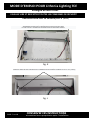
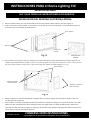
PENDANT MOUNT INSTALLATION
1. Remove the side cover by unscrewing two side screws and remove side cover. (See Fig. R)
2. Slide out front panel, if applicable, to permit installation process. Installer will need to remove bonding screw on Standard
Exit Signs.
3. To use with a pendant, remove the upper tray screws, and upper tray (Emergency units will contain battery inside tray) and
remove the top middle knockout (See Fig S). Pull the harness back through the battery tray (See Fig I).
Fig. R
SIDE SCREWS
SIDE COVER
Standard Exit Sign
BONDING SCREW
MIDDLE KNOCK OUT
UPPER TRAY SCREWS
(2ND SCREW IS DIRECTLY
ACROSS ON THE LEFT SIDE)
UPPER TRAY
Fig. S
(Pendant mount not included)

LED Steel Sign
INSTRUCTIONS FOR Lithonia Lighting TCE
READ AND FOLLOW ALL SAFETY INSTRUCTIONS
SAVE THESE INSTRUCTIONS
and deliver to owner after installation
PAGE: 12 of 18
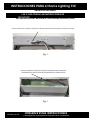
PENDANT MOUNT INSTALLATION (CONT.)
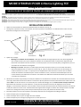
4. Mount the pendant to the top of unit using ½” Threaded Nipple Conduit Fitting, and a ½” Threaded Conduit Coupler Fitting.
(See Fig T)
5. Pass the wires through the pendant, reinstall the upper tray, and torque the upper tray screws to 10.6 in lbs (1.2 N ms) (See
Fig I). If applicable ensure the pendant mount does not interfere, or make contact, with the battery in the upper tray when
reinstalled.
6. Use code-approved connectors to make the connection inside the unit. Connect the hot wire to the red lead. Connect neutral
wire to the white lead. The ground wire (green lead) needs to be connected in accordance with the local codes. DO NOT
energize the circuit at this time (See Wiring Diagram). For Units with Remote Lamp Wires: Connect remote wires to the
remote output. The yellow wire is the positive remote wire and blue is the negative (See Wiring Diagram). If no remote
lamps are connected, make sure remote wire harness is removed from the unit to prevent shorting.
7. Proceed to step 10 for Chicago Panel.
8. Proceed to step 11 and 12 for Standard Exit Sign.
9. Proceed to step 13 for Running Man.
10. Slide Chicago Glass Panel into grooves (See Fig U). If a double-sided panel is wanted add panels to both sides.
Proceed to step 14.
UL924 CERTIFIED GLASS PANELS
CHP ENA CHP SNA
CITY OF CHICAGO, IL
NON UL924 CERTIFIED
GLASS PANELS
CHP ERA
CHP ELFA
CHP EDA
CHP SRA
CHP SLFA
CHP SDA
Fig. U
½” THREADED
NIPPLE CONDUIT
FITTING
½” THREADED
COUPLING CONDUIT
FITTING
PENDANT
½” CONDUIT
½” THREADED
NIPPLE CONDUIT
FITTING
½” THREADED
CONDUIT COUPLER
FITTING
Fig. T
GROOVES
SLIDE PANEL
(Pendant mount not included)

LED Steel Sign
INSTRUCTIONS FOR Lithonia Lighting TCE
READ AND FOLLOW ALL SAFETY INSTRUCTIONS
SAVE THESE INSTRUCTIONS
and deliver to owner after installation
PAGE: 13 of 18
PENDANT MOUNT INSTALLATION (CONT.)
11. Standard Exit Sign: Slide 1 Red or 1 Green Diffuser into Standard Exit Panel Grooves (See Fig V).
12. Standard Exit Sign: Slide Standard Exit Panel into grooves (See Fig W), with Standard Exit Panel facing out, and torque
bonding screw to 10.6 in-lbs. (1.2Nm) Proceed to step 14.
13. Running Man Sign: Place the Running Man sign over the white diffuser and slide stacked signs into the grooves with Running
Man panel facing outward, RM no Arrow panel is shown (See Fig. X).
REMOVE RED DIFFUSER
Fig. V
Fig. W
GROOVES
BONDING SCREW
Note: There is a
similar screw on
the backplate that
if removed should
be torqued to the
same value.
REMOVE DESIRED CHEVRON(S) REPLACE WITH RED OR GREEN DIFFUSER
Fig. X
GROOVES
DIFFUSER
RM PANEL
(Pendant mount not included)

LED Steel Sign
INSTRUCTIONS FOR Lithonia Lighting TCE
READ AND FOLLOW ALL SAFETY INSTRUCTIONS
SAVE THESE INSTRUCTIONS
and deliver to owner after installation
PAGE: 14 of 18
PENDANT MOUNT INSTALLATION (CONT.)
14. Replace the side cover and torque the side screws to 10.6 in-lbs (1.2Nm) (See Fig Y).
15. Energize the unit with AC supply. If the unit includes a battery, the charge indicator will illuminate green for charging. Allow
battery to charge for 24 hours before initial testing.
Fig. Y
TEST SWITCH AND LED
(EMERGENCY ONLY)
SIDE SCREWS
(Pendant mount not included)

LED Steel Sign
INSTRUCTIONS FOR Lithonia Lighting TCE
READ AND FOLLOW ALL SAFETY INSTRUCTIONS
SAVE THESE INSTRUCTIONS
and deliver to owner after installation
PAGE: 15 of 18
OPERATION:
For AC only
1. Apply AC Power and sign should illuminate.
For Battery Backup units
1. Apply AC Power and sign should illuminate.
2. Press test switch to simulate power removal and observe if sign illuminates.
3. Once you release the TEST switch the sign will be powered by AC power and the status indicator will illuminate green for
charging.
4. The charger board will continue charging the battery to maintain a fully charged state.
NOTE: Allow the battery (if applicable) to charge for a minimum of 24 hrs after installation or after a power failure before
conducting a 90-minute test.
NOTE: EL, HO, and EHO are furnished with a sophisticated solid state transfer switch which will automatically disconnect
the emergency back-up lights from the battery if the battery has been discharged to the end of its useful output. Sign will
still illuminate during AC power only.
MAINTENANCE:
CAUTION: Always turn OFF AC power to the equipment before servicing. Operator should disconnect battery (if applicable)
and the sign is still illuminated to remove power. Servicing should be performed only by a qualified service technician. Only
manufacturer SUPPLIED or APPROVED replacement parts must be used.
BATTERY: The battery (if applicable) supplied with this unit requires ZERO maintenance. However, it should be tested
periodically and replace when it no longer operates the connected fixtures for complete duration of a monthly 30-second or
annual 90-minute test.
NFPA 101 (current Life Safety Code) requires that all emergency lighting equipment be functionally tested every 30 days for a
minimum of 30 seconds and tested annually for full 90-minute duration. Written records of the testing are to be kept for
examination by the authority having jurisdiction.

LED Steel Sign
READ AND FOLLOW ALL SAFETY INSTRUCTIONS
SAVE THESE INSTRUCTIONS
and deliver to owner after installation
PAGE: 16 of 18
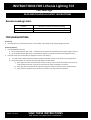
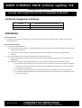
Remote Loading Limits
Product Maximum Continuous Remote Loading
TCE with HO 2.4W
TCE with EHO 6.6W
TROUBLESHOOTING:
For AC only
1. If the sign does not illuminate check the circuit breaker and validate the AC supply voltage is present.
For battery backup
1. The sign DOES NOT operate:
a) If the charge indicator light is OFF —Check the circuit breaker and validate the AC supply voltage is present.
b) If the charge indicator light is Red - Check that the battery is properly connected and charged for 24 hrs.
2. If remote lamps are connected to the equipment and are not working:
a) Turn OFF the AC supply, disconnect battery and disconnect the remote circuit wires from the equipment.
b) Reconnect battery, turn ON the AC supply and depress the test switch.
a) If the sign illuminates, then check the remote circuit for short or overload condition and correct as
required. Reconnect the circuit wires and restore AC power and battery connection.
b) If the sign does not illuminate after disconnecting the remote circuit wires, then replace battery.
c) If the previous step(s) does not resolve the problem, unit may need to be replaced.
INSTRUCTIONS FOR Lithonia Lighting TCE

LED Steel Sign
READ AND FOLLOW ALL SAFETY INSTRUCTIONS
SAVE THESE INSTRUCTIONS
and deliver to owner after installation
PAGE: 17 of 18
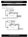
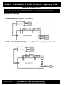
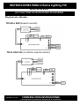
Wiring Diagram:
TCE EL ONLY (Non-HO / No Remote Support)
TCE HO or EHO (Remote Support)
INSTRUCTIONS FOR Lithonia Lighting TCE

LED Steel Sign
READ AND FOLLOW ALL SAFETY INSTRUCTIONS
SAVE THESE INSTRUCTIONS
and deliver to owner after installation
PAGE: 18 of 18
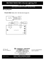
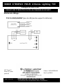
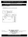
Wiring Diagram:
TCE AC ONLY (Non-HO / No Remote Support)
FCC Title 47,
Part 15, Subpart B Part No. 912-00378-001
Rev D , 04/2023
INSTRUCTIONS FOR Lithonia Lighting TCE

Enseigne en acier à DEL
MODE D’EMPLOI POUR Lithonia Lighting TCE
VEUILLEZ LIRE ET RESPECTER TOUTES LES CONSIGNES DE SÉCURITÉ
CONSERVEZ CES INSTRUCTIONS
et remettez-les au propriétaire après l’installation
PAGE: 1 sur 18
Lorsque de l’équipement électrique est utilisé, les précautions de sécurité élémentaires
suivantes devraient toujours être prises :
VEUILLEZ LIRE ET RESPECTER TOUTES LES CONSIGNES DE SÉCURITÉ
AVERTISSEMENT : LE NON-RESPECT DE CES INSTRUCTIONS ET DE CES AVERTISSEMENTS PEUT ENTRAÎNER LA MORT
OU DES DÉGÂTS MATÉRIELS IMPORTANTS. Pour votre sécurité, lisez et suivez attentivement les instructions et les mises en garde
suivantes avant d’installer ou d’effectuer l’entretien de cet appareil. Ces instructions n’ont pas la prétention de couvrir toutes les possibilités
d’installation et d’entretien. Si vous ne comprenez pas ces instructions et si d’autres informations sont requises, communiquez avec
LITHONIA LIGHTING ou avec votre distributeur LITHONIA LIGHTING local.
AVERTISSEMENT : RISQUE DE DÉCHARGE ÉLECTRIQUE –METTEZ TOUJOURS HORS TENSION LE CIRCUIT OU
L’ÉQUIPEMENT AVANT DE LE RACCORDER, DE LE DÉBRANCHER OU DE LE RÉPARER.
AVERTISSEMENT : NE PAS UTILISER DE MATÉRIAUX ABRASIFS NI DE SOLVANTS. L’UTILISATION DE CES SUBSTANCES
POURRAIT ENDOMMAGER LE LUMINAIRE ET ENTRAÎNER DES BLESSURES CORPORELLES.
AVERTISSEMENT :RISQUE DE BLESSURES CORPORELLES –Ce produit peut être tranchant aux extrémités. Portez des gants pour éviter
les coupures ou les écorchures lorsque vous sortez le produit
de la boîte et quand vous le manipulez, l’installez ou effectuez son entretien.
AVERTISSEMENT : RISQUE D’INCENDIE. Les lampes sont chaudes. Tenez les matériaux combustibles à distance des pièces chaudes.
Respectez tous les avertissements, recommandations et restrictions du fabricant de la lampe concernant le fonctionnement et l’entretien. Vérifiez
que les lampes sont bien en place.
IMPORTANTES MISES EN GARDE
•N’utilisez pas à l’extérieur. Convient pour une utilisation dans un emplacement humide 0 °C à 40 °C (32 °F à 104 °F).
•Consultez le code du bâtiment local pour connaître le câblage et l’installation homologués.
•Débranchez l’appareil du courant alternatif avant l’entretien ou l’installation.
•N’installez pas à proximité de fournaises au gaz ou électriques.
•N’utilisez pas cet équipement pour un usage autre que celui pour lequel il a été conçu.
•L’utilisation d’accessoires non recommandés par le fabricant pourrait être dangereuse.
•Tous les travaux d’entretien de cet appareil doivent être effectués par du personnel qualifié.
•Il faut installer cet appareil à un endroit et à une hauteur qui permettront d’éviter que les personnes non
autorisées n’y apportent des modifications.
•Soyez prudent lors de l’entretien des batteries.
•Vérifiez que les extrémités des câbles sont bien fixées et que les câbles ont été correctement replacés dans les
canaux de câbles appropriés.
MISES EN GARDE IMPORTANTES : Lors de l’utilisation d’un appareil électrique, des précautions de sécurité
élémentaires doivent toujours être suivies, telles que :
La page est en cours de chargement...
La page est en cours de chargement...
La page est en cours de chargement...
La page est en cours de chargement...
La page est en cours de chargement...
La page est en cours de chargement...
La page est en cours de chargement...
La page est en cours de chargement...
La page est en cours de chargement...
La page est en cours de chargement...
La page est en cours de chargement...
La page est en cours de chargement...
La page est en cours de chargement...
La page est en cours de chargement...
La page est en cours de chargement...
La page est en cours de chargement...
La page est en cours de chargement...
La page est en cours de chargement...
La page est en cours de chargement...
La page est en cours de chargement...
La page est en cours de chargement...
La page est en cours de chargement...
La page est en cours de chargement...
La page est en cours de chargement...
La page est en cours de chargement...
La page est en cours de chargement...
La page est en cours de chargement...
La page est en cours de chargement...
La page est en cours de chargement...
La page est en cours de chargement...
La page est en cours de chargement...
La page est en cours de chargement...
La page est en cours de chargement...
La page est en cours de chargement...
La page est en cours de chargement...
-
 1
1
-
 2
2
-
 3
3
-
 4
4
-
 5
5
-
 6
6
-
 7
7
-
 8
8
-
 9
9
-
 10
10
-
 11
11
-
 12
12
-
 13
13
-
 14
14
-
 15
15
-
 16
16
-
 17
17
-
 18
18
-
 19
19
-
 20
20
-
 21
21
-
 22
22
-
 23
23
-
 24
24
-
 25
25
-
 26
26
-
 27
27
-
 28
28
-
 29
29
-
 30
30
-
 31
31
-
 32
32
-
 33
33
-
 34
34
-
 35
35
-
 36
36
-
 37
37
-
 38
38
-
 39
39
-
 40
40
-
 41
41
-
 42
42
-
 43
43
-
 44
44
-
 45
45
-
 46
46
-
 47
47
-
 48
48
-
 49
49
-
 50
50
-
 51
51
-
 52
52
-
 53
53
-
 54
54
-
 55
55


Lithonia Lighting TCE Steel Running Man Sign Guide d'installation
- Taper
- Guide d'installation
- Ce manuel convient également à
Documents connexes
-
Lithonia Lighting TCC Commercial Steel Running Man Combo Guide d'installation
-
Lithonia Lighting LTKMSBK MR16GU10 LED 2700K DBL M4 Manuel utilisateur
-
-
-
-
-
-
-
Lithonia Lighting OFL2 LED P3 50K MVOLT IS DDBXD M2 Guide d'installation
-
Autres documents
-
AcuityBrands ELM4L Manuel utilisateur
-
Satco 67-120 Mode d'emploi
-
PLT SOLUTIONS Color Selectable LED Exit Sign Mode d'emploi
-
PLT SOLUTIONS Twin Head LED Emergency Light Manuel utilisateur
-
-
AcuityBrands ELM2L 120V-347V) Emergency Lighting Unit Manuel utilisateur
-
Hager XEVA205 Manuel utilisateur