
PL
DE
FR
NL
EN
Originalbetriebsanleitung für SELVE-Antriebe
Bitte sorgfältig aufbewahren!
S. 2
Operating instruction for SELVE motors
Please keep in a safe place!
P. 12
Notice de réglage des moteurs SELVE
Prière de conserver cette notice !
P. 22
Afstelhandleiding SELVE buismotoren
Deze handleiding zorgvuldig bewaren!
Blz. 32
Instrukcja obsługi SELVE elektroniczne siłowniki
Proszę zachować instrukcję!
Str. 42
SP-NHK

2
Sicherheitshinweise
1. Sicherheitshinweise
Warnung!
Wichtige Sicherheitshinweise für Montage und Betrieb!
Für die Sicherheit von Personen ist es wichtig, diese Anwei-
sungen zu befolgen, da falsche Bedienung und Montage zu
ernsthaften Verletzungen führen kann.
Die Anweisungen sind aufzubewahren.
• Folgende Punkte sind zu berücksichtigen:
· Die geltenden Gesetze, Normen und Vorschriften
· Landesspezifische Bedingungen
· Die Vorschriften der örtlichen Energieversorgungsunternehmen
sowie die Bestimmungen für Feuchträume nach VDE 0100
· Die Sicherheitshinweise der DIN EN 60335
· Der Stand der Technik zum Zeitpunkt der Installation
· Diese Betriebsanleitung sowie Betriebsanleitungen für angeschlos-
sene Komponenten
• Der Anschluss des Antriebs darf nur durch autorisiertes Fachperso-
nal vorgenommen werden. Bei der Installation oder Wartung ist die
Anlage spannungsfrei zu schalten.
• Bei Installation, Wartung oder Reparatur des Antriebs muss eine all-
polige Trennung vom Netz mit mindestens 3 mm Kontaktöffnungs-
weite pro Pol vorgesehen werden (DIN EN 60335).
Es müssen Sicherheitsmaßnahmen gegen unbeabsichtigtes Ein-
schalten getroffen werden.
• Vor der Installation des Antriebs sind alle nicht benötigten Leitun-
gen zu entfernen und jegliche Einrichtung, die nicht für die Betäti-
gung mit Kraftantrieb benötigt werden, außer Betrieb zu setzen.
• Die Betriebsanleitung ist Bestandteil des Gerätes und der Gewähr-
leistungsbedingungen. Sie ist dem Elektriker und dem Benutzer zu
überreichen.

3
DE
Sicherheitshinweise
• Die Anlage ist häufig auf mangelnde Balance oder auf Anzeichen
von Verschleiß oder beschädigte Federn und Anschlussleitungen zu
überprüfen und darf nicht betrieben werden, wenn Reparaturen
oder Korrekturen notwendig sind. Prüfen Sie den Antrieb und die
gesamte Anlage auf Beschädigungen. Bei Beschädigungen am An-
trieb, insbesondere der Anschlussleitung, darf dieser nicht in Betrieb
genommen werden!
• Der Antrieb ist nur im eingebauten Zustand funktionsfähig und darf
nur im spannungsfreien Zustand angeschlossen werden. Zur Kopp-
lung des Antriebs mit dem angetriebenen Teil dürfen nur Adapter
und Kupplungen aus dem aktuellen SELVE-Katalog verwendet wer-
den. Der kleinste Wellendurchmesser für SELVE-Antriebe der Bau-
reihe 1 (z. B. SE.. 1/…) beträgt 40 mm, für Baureihe 2 (z. B.
SE.. 2/…) 50 mm und für Baureihe 3 (z. B. SE.. 3/…) 60 mm. Bei
Nutrohren ist ggf. eine exzentrische Ausführung von Kupplung und
Laufring zu beachten.
• Nennmoment und Einschaltdauer müssen auf die Anforderungen
des angetriebenen Produkts abgestimmt sein. Die technischen
Daten können dem Typenschild des Antriebs entnommen werden.
• Wird ein Antrieb in einer Markise verwendet, so darf die Markise
nicht betrieben werden, wenn Arbeiten wie z. B. Wartung oder
Fensterputzen in der Nähe ausgeführt werden. Bei automatisch ge-
steuerten Markisen muss die Markise bei oben genannten Arbeiten
vom Versorgungsnetz getrennt werden.
• Die Antriebe können von Kindern ab 8 Jahren und von Personen mit
verminderten physischen, sensorischen oder mentalen Fähigkeiten
oder mit mangelnder Erfahrung und Wissen betrieben werden,
wenn sie beaufsichtigt werden oder hinsichtlich des sicheren Ge-
brauchs des Gerätes unterwiesen wurden und die damit verbunde-
nen Gefahren verstanden haben.
• Gegenstände sind aus dem Fahrbereich fernzuhalten. Der Fahrbe-
reich muss während des Betriebs einsehbar sein. Beobachten Sie
die Anlage während des Betriebes und halten Sie Personen von Ihr
fern. Verwenden Sie nur verriegelte Schaltelemente.

4
• Bei Antrieben, die mit einem Schalter mit AUS-Voreinstellung ge-
steuert werden, muss der Schalter in Sichtweite des Gerätes, von
sich bewegenden Teilen entfernt und in einer Höhe von über 1,5 m
angebracht werden.
• Ungeschützte, bewegliche Teile des Antriebs müssen in einer Höhe
von mehr als 2,5 m vom Boden oder einer anderen Ebene, die Zu-
gang zum Antrieb gewährt, montiert sein. Ein Mindestabstand von
40 cm zwischen sich bewegenden Teilen und benachbarten Gegen-
ständen ist einzuhalten.
• Kindern nicht erlauben, mit ortsfesten Steuerungen zu spielen.
Fernsteuerungen von Kindern fernhalten.
• Bei Einsatz in Markisen, bei denen sich im ausgefahrenen Zustand
Anlagenteile näher als 2 m vom Boden oder einer anderen Zu-
gangsebene zur Anlage befinden können, muss ein horizontaler
Mindestabstand von 40 cm zu anderen festen Objekten gewährleis-
tet sein.
• Im Außenbereich und bei Unterputzinstallation ist die weiße
PVC-Motoranschlussleitung im Rohr zu verlegen. Antriebe mit
PVC(H05VV-F)-Leitung dürfen nur im Innenbereich verwendet
werden. Wenn die Netzanschlussleitung des Antriebs beschädigt
ist, muss sie durch den Hersteller, seinen Kundendienst oder einer
ähnlich qualifizierten Person ersetzt werden.
• Schäden durch falsche Handhabung, falsche Verkabelung, Gewalt-
anwendung, Fremdeingriff in den Antrieb oder nachträgliche Verän-
derungen an der Anlage sowie Nichtbeachtung der Sicherheitshin-
weise und dadurch entstandene Folgeschäden fallen nicht unter die
Gewährleistung.
• Verwenden Sie nur unveränderte SELVE-Originalteile und -Zubehör.
Bitte beachten Sie hierfür den aktuellen SELVE-Katalog und die
SELVE-Website www.selve.de
Sicherheitshinweise

5
DE
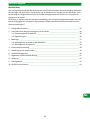
1. Sicherheitshinweise ________________________________________________________ 2
2. Informationen zu Eigenschaften des Antriebs ___________________________________ 6
2.1. Bestimmungsgemäße Verwendung ________________________________________ 6
2.2. Eigenschaften _________________________________________________________ 6
3. Montage _________________________________________________________________ 7
3.1. Einbau des Antriebs in die Welle __________________________________________ 7
3.2. Ablagerung des Antriebs ________________________________________________ 8
4. Elektrischer Anschluss ______________________________________________________ 8
5. Einstellung der Endlagen ____________________________________________________ 9
6. Technische Daten _________________________________________________________ 10
7. Allgemeine Konformitätserklärung ___________________________________________ 11
8. Entsorgung ______________________________________________________________ 11
9. Hinweise für die Fehlersuche _______________________________________________ 11
10. SELVE-Service-Hotline _____________________________________________________ 11
Inhaltsverzeichnis
Sehr geehrter Kunde,
Sie haben sich mit dem Kauf eines SELVE-Antriebs für ein Qualitätsprodukt aus dem Hause
SELVE entschieden. Diese Betriebsanleitung beschreibt Ihnen den Einbau und die Bedienung
des Antriebs. Bitte lesen Sie unbedingt diese Betriebsanleitung vor der Inbetriebnahme des
SELVE-Antriebs und beachten Sie die Sicherheitshinweise.
SELVE ist nach Erscheinen der Betriebsanleitung nicht haftbar für Änderungen der Normen
und Standards! Technische Änderungen vorbehalten!

6
Informationen zu Eigenschaften des Antriebs
2. Informationen zu Eigenschaften des Antriebs
2.1. Bestimmungsgemäße Verwendung
Der Antrieb SP-NHK ist ein Antrieb mit mechanischer Endabschaltung und Notbedienung
über eine Handkurbel.
Der Antrieb SP-NHK darf nur für den Betrieb von Rollläden, Markisen und (Zip-)Screens einge-
setzt werden.
Es werden feste Anschläge für die obere Endlage empfohlen!
2.2. Eigenschaften
Die Nothandkurbel darf nur im stromlosen Zustand betätigt werden.
Der Rollladen sollte über die Nothandkurbel nur soweit betrieben werden, bis er in Aufwärts-
richtung kurz vor dem Anschlag steht oder in Abwärtsrichtung die Lüftungsschlitze geschlos-
sen sind. Wird die Kurbel darüber hinaus bewegt, besteht die Gefahr, dass der Rollladen
beschädigt wird.
Die eingestellten Endpositionen werden bei Betätigung der Nothandkurbel nicht verändert
und der Antrieb ist anschließend sofort wieder betriebsbereit.
Die Luftschallemission des Antriebs liegt wesentlich unterhalb von 70 dB(A). Je nach Art der
Anlagenbeschaffenheit ist eine Verstärkung der Antriebslautstärke möglich und kann durch
Einsatz geeigneter Maßnahmen (z. B. Dämmung des Kastens, Verwendung von Schallschutz-
dübeln etc.) reduziert werden.
Der Antrieb ist für Links- und Rechtseinbau geeignet und kann mit herkömmlichen, für Rollla-
den- und Sonnenschutzantriebe geeigneten Schaltern, Tastern und Steuerungsanlagen
betrieben werden.
Das Antriebsdrehmoment muss für das Behanggewicht richtig ausgewählt werden.
Achtung! Um die in der Norm DIN EN 13659 vorgeschriebene Bedienkraft der Kurbelstange
nicht zu überschreiten, muss bei dem Antrieb SP 2/20-NHK (Über setzungsverhältnis 13:1)
eine Kurbelstange mit einer Ausladung von min. 180 mm (Art.-Nr. 278245) verwendet wer-
den.

7
DE
Montage
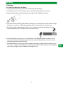
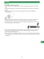
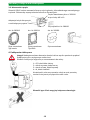
3. Montage
3.1. Einbau des Antriebs in die Welle
1. Laufring und Kupplung entsprechend der Wellengröße festlegen.
2. Laufring über den Antrieb schieben und an dem Motorkopf exakt positionieren.
3. Kupplung aufschieben und Kupplungssicherung (Artikel 288500) einstecken.
4. Den Antrieb formschlüssig in die Welle einschieben. Der Antrieb darf hierbei keine Schläge
bekommen. Laufring- und Kupplungsadapter dürfen in der Welle kein Spiel haben.
5. Den Antrieb falls notwendig axial sichern, z. B. durch Verschrauben der Welle mit dem
Kupplungsadapter. Nicht im Bereich des Antriebs bohren!
6. Die vorbereitete Einheit mit ca. 3 mm Axialspiel in den Rollladenkasten einbauen (siehe
hierzu auch Kapitel 3.2. Ablagerung des Antriebs) und die Walzen kapsel mit einer kurzen
Schraube gegen Verschieben sichern.
7. Die Motorleitung nicht knicken und so verlegen, dass keine Schäden daran entstehen kön-
nen. Um zu verhindern, dass Wasser in den Antrieb läuft, die Motorleitung in einem Bogen
nach unten verlegen, damit Fließwasser abtropfen kann.

8
Montage/Elektrischer Anschluss
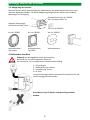
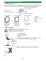
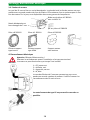
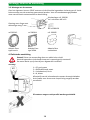
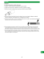
3.2. Ablagerung des Antriebs
Generell können SELVE-Antriebe über die Außenkontur des Motorkopfes oder über einen
Vierkant abgelagert werden. Für beide Ablagerungsmöglichkeiten stehen verschiedene
Motorlager zur Verfügung.
Adaption Gelenklager
mit Sechskant-Stab 7 mm
Vierkantflansch Art.-Nr. 282010
inkl. Schrauben M5 x 10
z. B. Art.-Nr. 280120
Art.-Nr. 282012
Aufsatzelement
Typ Inoutic
Art.-Nr. 282011
Aufsatzelement
Typ VEKA
Art.-Nr. 282005
Vorbauelement
4. Elektrischer Anschluss
Warnung!
Achtung! Verletzungsgefahr durch Stromschlag!
Anschluss nur im spannungsfreien Zustand!
Der Antrieb ist nur im eingebauten Zustand funktionsfähig.
1 = PE, gelb-grün
2 = Rechtsdrehung, schwarz
3 = Linksdrehung, braun
4 = N, blau
Je nach Einbaulage müssen eventuell die Anschlüsse für die
Laufrichtung getauscht werden.
Antriebe des Typs SP dürfen nicht parallel geschaltet
werden.

9
DE
Einstellung der Endlagen
5. Einstellung der Endlagen
Den Antrieb jetzt ohne angehängten Rollladen abwärts fahren, bis der Antrieb selbsttätig
abschaltet. Mit der entsprechenden Einstellschraube die untere Endlage so einstellen (siehe
weiter hinten in diesem Kapitel), dass der Rollladen befestigt werden kann.
Nach der Einstellung der unteren Endposition den Rollladen an der Welle befestigen und
anschließend die Aufwärtsrichtung betätigen. Während der Aufwärtsfahrt die obere Endlage
mit der entsprechenden Einstell schraube einstellen.
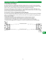
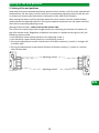
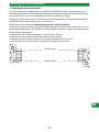
Einstellung der Endlagen, Leitungsaustritt auf der Rückseite:
Die auf der Abschaltung aufgedruckten geraden Pfeile geben die Drehrichtung der Rollladen-
welle an. Unabhängig davon, ob der Antrieb rechts oder links eingebaut wird, gelten grund-
sätzlich folgende Regeln:
• Endschaltereinstellung untere Rollladenposition, Einstellschraube 1 drehen
• Endschaltereinstellung obere Rollladenposition, Einstellschraube 2 drehen
• Einstellschraube im Uhrzeigersinn (+) drehen, bedeutet längeren Rollladenweg
• Einstellschraube gegen den Uhrzeigersinn (-) drehen, bedeutet kürzeren Rollladenweg
Einstellschraube 1
Einstellschraube 2

10
Einstellung der Endlagen/Technische Daten
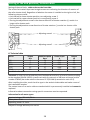
Einstellung der Endlagen, Leitungsaustritt auf der Vorderseite:
Die auf der Abschaltung aufgedruckten geraden Pfeile geben die Drehrichtung der Rollladen-
welle an. Unabhängig davon, ob der Antrieb rechts oder links eingebaut wird, gelten grund-
sätzlich folgende Regeln:
• Endschaltereinstellung untere Rollladenposition, Einstellschraube 2 drehen
• Endschaltereinstellung obere Rollladenposition, Einstellschraube 1 drehen
• Einstellschraube gegen den Uhrzeigersinn (+) drehen, bedeutet längeren Rollladenweg
• Einstellschraube im Uhrzeigersinn (-) drehen, bedeutet kürzeren Rollladenweg
Einstellschraube 1
Einstellschraube 2
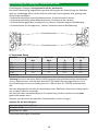
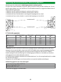
6. Technische Daten
Baureihe Drehmoment
Nm
Drehzahl
Rpm
Stromaufnahme
A
Leistung
W
2/6 6 16 0,38 88
2/7 7 17 0,41 95
2/10 10 17 0,45 105
2/15 15 17 0,66 152
2/20* 20 17 0,75 172
Einbauort:
*Achtung! Um die in der Norm DIN EN 13659 vorgeschriebene Bedienkraft der Kurbelstange
nicht zu überschreiten, muss bei dem Antrieb SP 2/20-NHK (Über setzungsverhältnis 13:1)
eine Kurbelstange mit einer Ausladung von min. 180 mm (Art.-Nr. 278245) verwendet wer-
den.
Nach der Montage des Antriebs den Antriebstyp in der Tabelle der technischen Daten markie-
ren und den Einbauort vermerken.
Die Antriebe haben standardmäßig eine 3 m Netzleitung, die fest installiert ist und nicht
gewechselt werden kann!
Hinweise zum Anschluss bei speziellen Steckverbindern sind zu erfragen.
Angaben für alle Antriebstypen:
Nennspannung: 230 V AC/50 Hz
Schutzart: IP 44
Betriebsart: S2 4 Min.
Technische Änderungen vorbehalten.

11
DE
Allgemeine Konformitätserklärung/Entsorgung/Fehlersuche
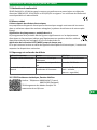
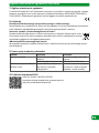
7. Allgemeine Konformitätserklärung
Hiermit erklärt die Firma SELVE GmbH & Co. KG, dass sich der Antrieb in Über einstimmung
mit den grundlegenden Anforderungen und den anderen relevanten Vorschriften der Richtli-
nien 2006/42/EG, 2014/30/EU und 2011/65/EU befindet. Die Konformitäts erklärung ist ein-
sehbar unter www.selve.de
8. Entsorgung
Getrennte Erfassung von Altgeräten
Elektro- und Elektronikgeräte, die zu Abfall geworden sind, sind vom Besitzer einer vom Haus-
müll getrennten Erfassung zuzuführen (spezielle Sammel- und Rückgabesysteme).
Möglichkeiten der Rückgabe von Altgeräten
Besitzer von Altgeräten aus privaten Haushalten können diese bei den Sammelstellen der
öffentlich-rechtlichen Entsorgungsträger oder bei den von Herstellern oder Vertreibern im
Sinne des ElektroG eingerichteten Rücknahmestellen unentgeltlich abgeben.
Bedeutung des Symbols „durchgestrichene Mülltonne“
Das auf Elektro- und Elektronikgeräten regelmäßig abgebildete Symbol einer durch-
gestrichenen Mülltonne weist darauf hin, dass das jeweilige Gerät am Ende seiner
Lebensdauer getrennt vom Hausmüll zu erfassen ist.
Länderspezifische Umsetzung von WEEE
Bzgl. der Entsorgung von Elektro- und Elektronikgeräten sind die nationalen Bestimmungen
zu beachten.
9. Hinweise für die Fehlersuche
Störung Ursache Beseitigung
Antrieb läuft nicht Elektrischer Anschluss ist feh-
lerhaft
Anschluss prüfen
Thermoschutzschalter hat
ausgelöst
5 bis 20 Minuten warten
Die Richtungen AUF und AB
sind vertauscht
Schwarze und braune Ader
falsch am Schalter angeschlos-
sen
Adern tauschen
(Schwarz = Rechtsdrehung,
braun = Linksdrehung)
10. SELVE-Service-Hotline
Hotline: Telefon 02351 925-299
Download der Betriebsanleitung
unter www.selve.de oder QR-Scan

12
Safety instructions
1. Safety instructions
Warning!
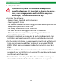
Important safety notes for installation and operation!
For safety of persons, it is important to observe the instruc-
tions, since wrong operation and installation may cause
severe injury. The instructions must be kept.
• Consider the following:
· Relevant laws, standards and instructions
· Country-specific terms
· The specifications of the local energy providers and stipulations for
damp rooms pursuant to VDE 0100
· The safety instructions of DIN EN 60335
· The state of the technology at the time of installation
· This instruction manual and any operating instructions for
connected components
• This motor must only be connected by authorised specialists. For
installation and maintenance the system has to be de-energised.
• For the motor installation, a mains supply circuit break with at least
3 mm contact opening width per pole must be provided (DIN EN
60335). Safety measures against inadvertent activation must be in
place.
• Before installation of the motor, all cables not needed must be re-
moved and any facility that is not required for operation with power
must be put out of operation.
• This instruction manual is part of the device and the warranty con-
ditions. It has to be handed out to the electrician and operator.

EN
13
Safety instructions
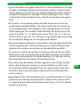
• Check the system at regular intervals for a lack of balance or for signs
of wear or damaged springs and connection cables. It must not be
used if repairs or corrections are required. Check the motor and the
complete installation for damage. In case of damage to the motor,
in particular to the connection line, it must not be taken into opera-
tion!
• The motor is only working when installed and must only be con-
nected when powered down. The motor must only be connected
to the powered part with adapters and couplings from the current
SELVE catalogue. The smallest shaft diameter for SELVE motors for
series 1 (e.g. SE.. 1/…) is 40 mm, for series 2 (e.g. SE.. 2/…) 50 mm
and for series 3 (e.g. SE.. 3/…) 60 mm. For grooved tubes, there may
be an eccentric design for the coupling and adapter.
• Nominal torque and duration of activation must be aligned with the
system requirements. Technical data such as nominal torque and
duration of activation are written on the identification plate.
• If a motor is used in an awning, the awning must not be operated
while work such as maintenance or window cleaning is carried out
nearby. For automatically controlled awnings, the awning must be
disconnected from the power for the above work.
• The motor may be used by children aged 8 or over and by people
with reduced physical, sensory or mental abilities or with a lack
of experience and knowledge if they are supervised or have been
trained in how to use the device safely and they understand the
risks involved.
• Keep objects from the operating area. It must be possible to see the
operation area during working process. Observe the system while
it is operating and keep other people away from it. Use only locked
switching elements.

14
• On motors which are controlled using a switch with an OFF setting,
the switch must be fitted in view of the device, away from moving
parts and at a height of over 1.5 m.
• Unprotected, moving parts of the motor must be installed at a
height of more than 2.5 m from the floor or another level which
provides access to the motor. A minimum distance of 40 cm be-
tween moving parts and neighbouring items must be maintained.
• Do not allow children to play with stationary control systems. Keep
remote controls away from children.
• If used in awnings on which extended system parts may be closer
than 2 m to the floor or another access level to the system, a min-
imum horizontal distance of 40 cm to other fixed objects must be
ensured.
• Outdoor or flush mounted, the motor connecting cable must be laid
in a conduit. Motors with PVC(H05VV-F)-cables must only be used
indoors. If the mains connection cable for the motor is damaged,
it must be replaced by the manufacturer, its customer service or a
similarly qualified person.
• Damage due to wrong handling, wrong wiring, use of force, interfer-
ence with the motor by a third party or subsequent changes to the
installation and any consequential damage arising from this is not
subject to the warranty.
• Use only unchanged SELVE original parts and accessories. For this,
please observe the current SELVE catalogue and the SELVE website
www.selve.de
Safety instructions

EN
15
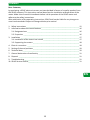
1. Safety instructions ________________________________________________________ 12
2. Information about the motor features ________________________________________ 16
2.1. Designated use _______________________________________________________ 16
2.2. Properties ___________________________________________________________ 16
3. Installation ______________________________________________________________ 17
3.1. Installation of the motor into a shaft ______________________________________ 17
3.2. Supporting the motors _________________________________________________ 18
4. Electric connection _______________________________________________________ 18
5. Setting of the end positions _________________________________________________ 19
6. Technical data ____________________________________________________________ 20
7. General declaration of conformity ___________________________________________ 21
8. Disposal ________________________________________________________________ 21
9. Troubleshooting __________________________________________________________ 21
10. SELVE Service Hotline ______________________________________________________ 21
Contents
Dear Customer,
by purchasing a SELVE electronic motor you have decided in favour of a quality product from
the SELVE company. This instruction manual describes the installation and operation of the
motor. Make sure to read this handbook before initial operation of the SELVE motor and
adhere to the safety instructions.
After publication of the operating instructions, SELVE shall not be liable for any changes to
norms and standards! Subject to change without prior notice!

16
Information about the motor features
2. Information about the motor features
2.1. Designated use
The motor SP-NHK is a motor with mechanical end limit stop and emergency operation via a
hand crank.
The motor SP-NHK must only be used for operating roller shutters, awnings and (zip-)screens.
Fixed limit stops for the upper end limit are recommended.
2.2. Properties
The emergency hand crank may only be operated when the power is off.
The roller shutter should only be operated by the emergency hand crank until it is shortly in
front of the limit stop in upward direction or in downward direction until the ventilation slits
are closed. In case the hand crank will be moved more than that, there is the risk that the
roller shutter will be damaged.
The set end limit positions will not be changed when using the emergency hand crank and
the motor is immediately ready for operation afterwards.
The airborne noise of the motor is significantly below 70 dB (A). Depending on the type of the
roller shutter/awning/screen a strengthening of the sound intensity of the motor is possible.
It can be reduced by use of appropriate measures (e.g. insulation of the box, using noise pro-
tection plugs, etc.).
The motor is suitable for left and right installation controlled with conventional switches, but-
tons and control systems that are suitable for roller shutter and sun control motors.
The motor torque has to be chosen correctly for the hanging weight.
Caution! In order to not exceed the prescribed operational force of a hand crank according to
the standard DIN EN 13659, a hand crank with an outreach of 180 mm minimum (article
number 278245) has to be used for the motor SP 2/20-NHK (transmission ratio 13:1).

EN
17
Installation
3. Installation
3.1. Installation of the motor into a shaft
1. Crown and coupling adapter need to be determined according to the size of the shaft.
2. Push the crown adapter over the shaft and position it precisely on the motor head.
3. Slide the coupling and plug-in the coupling locking device.
4. Push the motor into the shaft in a positive-locking way. The motor must not be subject to
any impacts. Crown and coupling adapters must not have any play inside the shaft.
5. Where required, secure the motor axially, e.g. by screwing the shaft to the coupling adapt-
er. Do not drill holes into the motor area!
6. Mount the prepared unit with approximately 3 mm axial play into the roller shutter box
(please also see chapter 3.2. Supporting the motors) and fix the cap against sliding with a
short screw.
7. Do not bend the motor cable and place it so that it cannot be damaged. To keep water
from getting into the motor, place the motor line in a bend direction downwards, so that
any water can drip off.

18
Installation/Electrical connection
3.2. Supporting the motors
In general, SELVE motors can be supported by means of a square or by means of the external
contour of the motor head. There are different motor brackets for all support options.
Adaptation for
hexagonal rod 7 mm
Square flange item no. 282010
incl. screws M5 x 10
e.g. item no. 280120
Item no. 282012
Top mounted
roller shutter
type Inoutic
Item no. 282011
Top mounted
roller shutter
type VEKA
Item no. 282005
Front mounted
roller shutter
4. Electric connection
Warning!
Caution! Risk of injury through an electric shock!
Connection only when de-energised!
Run the motor only after installation.
1 = PE, yellow-green
2 = Rotation right, black
3 = Rotation left, brown
4 = N, blue
Depending on the installation position, the connections for
the running direction may have to be exchanged
Motors of type SP must not be connected in parallel.

EN
19
Setting of the end positions
5. Setting of the end positions
Now move the motor downwards without attached roller shutter until the motor switches off
automatically. Set the lower end limit with the corresponding adjusting screw so that the roll-
er shutter can be mounted (see further information at the end of this chapter).
After setting the lower end limit position mount the roller shutter onto the shaft and after-
wards operate the upwards direction. During the upwards movement set the upper end limit
with the corresponding ad justing screw.
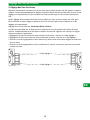
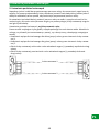
Setting of the end limits, cable outlet on the reverse side:
The on the limit switch imprinted straight arrows are indicating the direction of rotation of
the roller shutter shaft. Regardless of whether the motor is installed on the right or left, the
following rules are valid:
• Limit switch for lower shutter position, turn adjusting screw 1
• Limit switch for upper shutter position, turn adjusting screw 2
• Turning the adjustment screw in the direction of shutter rotation (+) results in a longer roll-
er shutter path
• Turning the adjustment screw reverse direction of shutter rotation (-) results in a shorter
roller shutter path
Adjusting screw 1
Adjusting screw 2

20
Setting of the end positions/Technical data
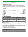
Setting of the end limits, cable outlet on the front side:
The on the limit switch imprinted straight arrows are indicating the direction of rotation of
the roller shutter shaft. Regardless of whether the motor is installed on the right or left, the
following rules are valid:
• Limit switch for lower shutter position, turn adjusting screw 2
• Limit switch for upper shutter position, turn adjusting screw 1
• Turning the adjustment screw in the reverse direction of shutter rotation (+) results in a
longer roller shutter path
• Turning the adjustment screw direction of shutter rotation (-) results in a shorter roller
shutter path
Adjusting screw 1
Adjusting screw 2
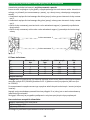
6. Technical data
Series Torque
Nm
Rotation speed
Rpm
Power Input
A
Output
W
2/6 6 16 0.38 88
2/7 7 17 0.41 95
2/10 10 17 0.45 105
2/15 15 17 0.66 152
2/20* 20 17 0.75 172
Installation location:
*Caution! In order to not exceed the prescribed operational force of a hand crank according
to the standard DIN EN 13659, a hand crank with an outreach of 180 mm minimum (article
number 278245) has to be used for the motor SP 2/20-NHK (transmission ratio 13:1).
After installing the drive, mark the drive type in the technical data table and make a note of
the installation location.
The motors have a 3 m mains cable as standard which is permanently installed and cannot be
replaced.
Information about connections using special connectors must be requested.
Information for all motor types:
Nominal voltage: 230 V AC/50 Hz
Safety class: IP 44
Operating mode: S2 4 min.
Subject to change without prior notice!
La page est en cours de chargement...
La page est en cours de chargement...
La page est en cours de chargement...
La page est en cours de chargement...
La page est en cours de chargement...
La page est en cours de chargement...
La page est en cours de chargement...
La page est en cours de chargement...
La page est en cours de chargement...
La page est en cours de chargement...
La page est en cours de chargement...
La page est en cours de chargement...
La page est en cours de chargement...
La page est en cours de chargement...
La page est en cours de chargement...
La page est en cours de chargement...
La page est en cours de chargement...
La page est en cours de chargement...
La page est en cours de chargement...
La page est en cours de chargement...
La page est en cours de chargement...
La page est en cours de chargement...
La page est en cours de chargement...
La page est en cours de chargement...
La page est en cours de chargement...
La page est en cours de chargement...
La page est en cours de chargement...
La page est en cours de chargement...
La page est en cours de chargement...
La page est en cours de chargement...
La page est en cours de chargement...
La page est en cours de chargement...
-
 1
1
-
 2
2
-
 3
3
-
 4
4
-
 5
5
-
 6
6
-
 7
7
-
 8
8
-
 9
9
-
 10
10
-
 11
11
-
 12
12
-
 13
13
-
 14
14
-
 15
15
-
 16
16
-
 17
17
-
 18
18
-
 19
19
-
 20
20
-
 21
21
-
 22
22
-
 23
23
-
 24
24
-
 25
25
-
 26
26
-
 27
27
-
 28
28
-
 29
29
-
 30
30
-
 31
31
-
 32
32
-
 33
33
-
 34
34
-
 35
35
-
 36
36
-
 37
37
-
 38
38
-
 39
39
-
 40
40
-
 41
41
-
 42
42
-
 43
43
-
 44
44
-
 45
45
-
 46
46
-
 47
47
-
 48
48
-
 49
49
-
 50
50
-
 51
51
-
 52
52


dans d''autres langues
- English: Selve SP-NHK, ≤ 20 Nm Operating instructions
- Deutsch: Selve SP-NHK, ≤ 20 Nm Bedienungsanleitung
- Nederlands: Selve SP-NHK, ≤ 20 Nm Handleiding
- polski: Selve SP-NHK, ≤ 20 Nm Instrukcja obsługi


