La page est en cours de chargement...

2
Avvertenze
• Questo prodotto Comelit è progettato e realizzato con lo scopo di
essere utilizzato nella realizzazione di impianti per comunicazione
audio e video in edifici residenziali, commerciali, industriali e in edifici
pubblici o ad uso pubblico.
• Tutte le attività connesse all’installazione dei prodotti Comelit devono
essere realizzate da personale tecnicamente qualificato, seguendo
attentamente le indicazioni di manuali / istruzioni dei prodotti stessi.
• Togliere l’alimentazione prima di effettuare qualsiasi operazione.
• Utilizzare conduttori con sezione adeguata in funzione delle distanze,
rispettando le indicazioni riportate nel manuale di sistema.
• Si consiglia di non posare i conduttori per l’impianto nella stessa
tubazione dove transitano i cavi di potenza (230V o superiori).
• Per l’utilizzo sicuro dei prodotti Comelit è necessario: seguire con
attenzione le indicazioni di manuali e istruzioni; curare che l’impianto
realizzato con i prodotti Comelit non sia manomesso / danneggiato.
• I prodotti Comelit non prevedono interventi di manutenzione ad
eccezione delle normali operazioni di pulizia, da effettuarsi comunque
secondo quanto indicato in manuali / istruzioni. Eventuali riparazioni
devono essere effettuate: per i prodotti, esclusivamente da Comelit
Group S.p.A., per gli impianti, da personale tecnicamente qualificato.
• Comelit Group S.p.A. non assume alcuna responsabilità per usi
differenti da quello previsto e mancato rispetto di indicazioni ed
avvertenze presenti in questo manuale / istruzioni. Comelit Group
S.p.A. si riserva comunque il diritto di modificare in qualsiasi momento
e senza preavviso quanto descritto nel presente manuale / istruzioni.
Warning
• This Comelit product was designed for use in the creation of audio and
video communication systems in residential, commercial or industrial
settings and in public buildings or buildings used by the public.
• All activities connected to the installation of Comelit products must be
carried out by qualified technical personnel, with careful observation
of the indications provided in the manuals / instruction sheets
supplied with those products.
• Cut off the power supply before carrying out any maintenance
procedures.
• Use wires with a cross-section suited to the distances involved,
observing the instructions provided in the system manual.
• We advise against running the system wires through the same duct as
the power cables (230V or higher).
• To ensure Comelit products are used safely: carefully observe the
indications provided in the manuals / instruction sheets and make
sure the system created using Comelit products has not been
tampered with / damaged.
• Comelit products do not require maintenance aside from routine
cleaning, which should be carried out in accordance with the
indications provided in the manuals / instruction sheets. Any repair
work must be carried out: for the products themselves, exclusively by
Comelit Group S.p.A., for systems, by qualified technical personnel.
• Comelit Group S.p.A. does not assume any responsibility for:
any usage other than the intended use; non-observance of the
indications and warnings contained in this manual / instruction sheet.
Comelit Group S.p.A. nonetheless reserves the right to change the
information provided in this manual / instruction sheet at any time and
without prior notice.
Avertissements
• Ce produit Comelit a été conçu et réalisé pour être utilisé dans la
réalisation d'installations de communication audio et vidéo dans
des bâtiments résidentiels, commerciaux, industriels et publics ou à
usage public.
• Toutes les opérations liées à l'installation des produits Comelit sont
réservées à des techniciens qualifiés qui devront suivre attentivement
les consignes des Manuels / Instructions desdits produits.
• Couper l'alimentation avant d'effectuer toute opération.
• Utiliser des conducteurs d'une section adéquate en fonction des
distances et en respectant les explications contenues dans le manuel
du système.
• Il est conseillé de ne pas poser les conducteurs destinés à
l’installation dans la canalisation destinée aux câbles de puissance
(230 V ou plus).
• Pour utiliser les produits Comelit en toute sécurité : suivre
attentivement les consignes contenues dans les Manuels /
Instructions; s'assurer que l’installation réalisée avec les produits
Comelit n'est pas sabotée / endommagée.
• Les produits Comelit sont sans maintenance, exception faite pour les
opérations de nettoyage qui devront être effectuées selon les consignes
contenues dans les Manuels / Instructions. Les réparations concernant :
les produits, sont réservées exclusivement à Comelit Group S.p.A., les
installations, sont réservées à des techniciens qualifiés.
• Comelit Group S.p.A. ne sera pas tenue pour responsable en cas
d'utilisation contraire aux indications, de non-respect des indications
et des recommandations présentes dans ce Manuel / Instructions.
Comelit Group S.p.A. se réserve le droit de modifier à tout moment
et sans préavis le contenu de ce Manuel / Instructions.
Waarschuwingen
• Dit product van Comelit is ontworpen en ontwikkeld om te worden
gebruikt bij de realisatie van audio- en videocommunicatiesystemen
In woningen, winkels, bedrijven en openbare gebouwen of in
openbare ruimtes.
• Alle functies die zijn aangesloten op de installatie van de Comelit-
producten moeten zijn uitgevoerd door gekwalificeerd technisch
personeel, volgens de aanwijzingen in de handleiding/instructies van
de betreffende producten.
• Sluit de voeding af voordat u onderhoudswerkzaamheden uitvoert.
• Gebruik geleiders met een geschikte doorsnede, afhankelijk van
de afstanden, volgens de aanwijzingen in de handleiding van de
installatie.
• Het is raadzaam om de kabels voor de installatie niet in dezelfde
leiding te plaatsen als die waar de vermogenskabels (230v of hoger)
doorheen lopen.
• Voor een veilig gebruik van de producten Comelit is het volgende
noodzakelijk: het zorgvuldig opvolgen van de aanwijzingen in de
handleiding/instructies, ervoor zorgen dat de installatie die met
de Comelit-producten is uitgevoerd niet wordt gesaboteerd /
beschadigd raakt.
• De producten van Comelit hebben geen onderhoud nodig, behalve de
normale reiniging, welke moet worden uitgevoerd zoals is aangegeven
in de handleiding/instructies. Eventuele reparaties moeten worden
uitgevoerd voor de producten, uitsluitend door Comelit Group
S.p.A., voor de installatie, door gekwalificeerd technisch personeel.
• Comelit Group S.p.A. is niet verantwoordelijkheid voor andere
toepassingen dan het beoogde gebruik, het niet in acht nemen van
de aanwijzingen en waarschuwingen in deze handleiding/instructies.
Comelit Group S.p.A. behoudt zich het recht voor om op elk
moment, zonder waarschuwing vooraf, wijzigingen aan te brengen in
deze handleiding/instructies.
Hinweise
• Dieses Comelit-Produkt ist für den Einsatz in Anlagen für Audio-
und Video-Kommunikation in Wohngebäuden, Gewerbe- und
Industrieanlagen, in öffentlichen Gebäuden und für den öffentlichen
Gebrauch konzipiert.
• Die Installation der Comelit-Produkte darf nur durch Fachkräfte
unter genauer Befolgung der Anweisungen in den technischen
Handbüchern / den Bedienungsanleitungen erfolgen.
• Vor Eingriffen an der Anlage immer die Spannungsversorgung
unterbrechen.
• Leiter mit einem für die Entfernung bemessenen Querschnitt
verwenden und die im Handbuch der Anlage aufgeführten
Anweisungen einhalten.
• Es wird empfohlen, die Leiter der Anlage nicht in den Rohren der
Leistungskabel (230 V oder höher) zu verlegen.
• Sicherer Umgang mit Comelit-Produkten: Halten Sie sich
strikt an die Angaben in den technischen Handbüchern / den
Bedienungsanleitungen. Nehmen Sie keine Änderungen an
der Anlage mit Comelit-Produkten vor und vermeiden Sie
Beschädigungen.
• Die Comelit-Produkte erfordern keine Wartungsarbeiten, abgesehen
von der normalen Reinigung, die entsprechend den Anweisungen
in den technischen Handbüchern / den Bedienungsanleitungen
auszuführen ist. Eventuelle Reparaturen dürfen für die Produkte nur
durch die Firma Comelit Group S.p.A., an der Anlage nur durch
Fachkräfte ausgeführt werden.
• Comelit Group S.p.A. lehnt jede Haftung ab bei Schäden durch
bestimmungsfremden Gebrauch, Missachtung der Anweisungen
und Hinweise in dem vorliegenden technischen Handbuch / den
Bedienungsanleitungen. Comelit Group S.p.A. behält sich vor, jeder
Zeit und ohne Vorankündigung Änderungen an dem vorliegenden
technischen Handbuch / den Bedienungsanleitungen vorzunehmen.
La page est en cours de chargement...
La page est en cours de chargement...
La page est en cours de chargement...

1.
3.
2.
JP1
NC
NO
JP1
NC
NO
SE
-
SE
+
NC NO C
SE
-
SE
+
NC NO C
1
2
6
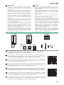
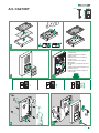
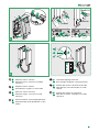
1. LED trimmer di regolazione luminosità pulsanti
2. CV2 cavallotto da tagliare per spegnere
l’illuminazione dei pulsanti
3. SPK trimmer di regolazione volume altoparlante
Sostituzione cartellini portanome
1. LED button brightness control trimmer
2. CV2 jumper to be removed when switching o the
button lighting
3. SPK loudspeaker volume adjustment trimmer
Changing nameplates
1.
LED variateur du réglage de la luminosité des boutons
2. CV2 chevalier à couper pour éteindre l’éclairage des
boutons
3. SPK variateur du réglage volume haut-parleur
Remplacement des étiquettes porte-noms
1. LED trimmer helderheidsregeling drukknoppen
2. CV2 draadbrug die moeten worden doorgeknipt om
de verlichting van de knoppen uit te schakelen
3. SPK trimmer volumeregeling luidspreker
Vervanging naamkaders
1. LED Trimmer zur Helligkeitsregelung der Tasten
2. CV2 Jumper durchtrennen zur Abschaltung der
Tastenbeleuchtung
3.
SPK Trimmer der Lautstärkeregelung des Lautsprechers
Austausch der Namensschilder
1. LED Trimmer de regulación de la luminosidad de los
pulsadores
2. CV2 Puente a quitar para apagar la iluminación de
los pulsadores
3. SPK Trimmer de regulación del volumen del altavoz
Sustitución de los tarjeteros
1. LED trimmer de regulação da luminosidade dos botões
2. CV2 abraçadeira a cortar para desligar a iluminação
dos botões
3. SPK trimmer de regulação do volume do altifalante
Substituição das etiquetas porta-nomes

7
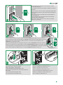
Programmazione indirizzi di chiamata diversi da quelli pre-programmati (1, 2, 3, 4)
Esistono 2 modalità di programmazione:
• Programmazione smart indirizzi
consecutivi: consente la programmazione
rapida dei pulsanti con indirizzi consecutivi
(ad esempio: 5, 6, 7, 8)
• Programmazione indirizzi specifici:
consente la programmazione di indirizzi
specifici (ad esempio: 25, 37, 70, 58)
Programming call addresses other than the pre-programmed options (1, 2, 3, 4)
There are 2 programming methods:
• Smart programming of consecutive
addresses: allows quick programming of
buttons with consecutive addresses (e.g.:
5, 6, 7, 8)
• Programming of specific addresses:
allows programming of specific addresses
(e.g.: 25, 37, 70, 58)
Programmation des adresses d’appel diérentes de celles qui ont été pré-programmées (1, 2, 3, 4)
2 modalités de programmation sont possibles :
• Programmation smart d’adresses
consécutives : permet de programmer
rapidement les boutons donnant accès à des
adresses consécutives (par exemple : 5, 6, 7, 8)
• Programmation d’adresses précises:
permet de programmer des adresses
spécifiques (par exemple : 25, 37, 70, 58)
Programmering van andere oproepadressen dan de voorgeprogrammeerde (bijvoorbeeld: 1, 2, 3, 4)
Er zijn 2 programmeermodi:
• Slim programmeren van opeenvolgende
adressen: hiermee kunnen drukknoppen
met opeenvolgende adressen snel worden
geprogrammeerd bijvoorbeeld: 5, 6, 7, 8
• Programmering van specifieke adressen:
maakt het programmeren van specifieke
adressen mogelijk (bijvoorbeeld: 25, 37, 70, 58)
Rufadressenprogrammierung für Adressen, die sich von den vorprogrammierten (1, 2, 3, 4) unterscheiden.
Es gibt 2 Programmiermodi:
• Intelligente Programmierung
aufeinanderfolgender Adressen:
ermöglicht die schnelle Programmierung
von Tasten mit aufeinanderfolgenden
Adressen (z.B.: 5, 6, 7, 8)
• Programmierung spezifischer Adressen:
ermöglicht das Programmieren von
spezifischen Adressen (z.B.: 25, 37, 70, 58)
Programación de direcciones de llamada diferentes a las preprogramadas (1, 2, 3 y 4)
Hay dos modos de programación:
• Programación inteligente de direcciones
consecutivas: permite programar de
forma rápida pulsadores con direcciones
consecutivas (por ejemplo: 5, 6, 7 y 8)
• Programación de direcciones
específicas: permite programar direcciones
específicas (por ejemplo: 25, 37, 70 y 58)
Programação de endereços de chamada diferentes dos pré-programados (1, 2, 3, 4)
Existem dois modos de programação:
• Programação Smart de endereços
consecutivos: permite programar
rapidamente botões com endereços
consecutivos (por exemplo: 5, 6, 7, 8)
• Programação de endereços específicos:
permite programar endereços específicos
(por exemplo: 25, 37, 70, 58)

art. CA9213
ON
S1
1 2
art. CA9210
ON
S1
1 2
art. CA9211
ON
S1
1 2
S1
LL
1 2 3
example
code 5
4
8
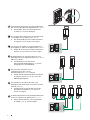
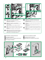
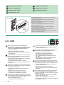
Programmazione smart indirizzi consecutivi
Collegare la pulsantiera Impostare S1 in funzione del numero di pulsanti Entrare in programmazione alzando PRC
Impostare l’indirizzo dell’appartamento che si desidera chiamare (ad esempio:
5) tramite i DIP-switch (vedi tabella pag 15)
Prendere nota delle impostazioni dei DIP-switch di S2
È obbligatorio eseguire le operazioni di programmazione nell'ordine indicato
Set the address of the apartment you want to call (for example: 5) using the
DIP switches (see table, page 15)
Smart programming of consecutive addresses
Take note of the S2 DIP-switch settings
The programming procedures must be carried out in the specified order
Set S1 according to the number of buttons
Enter programming mode by moving PRC upwards
Connect the entrance panel
Définir l’adresse de l’appartement à appeler (par exemple : 5) au moyen des
DIP-switch (voir tableau page 15)
Programmation smart d’adresses consécutives
Noter les réglages des DIP-switch de S2
Eectuer impérativement les opérations de programmation dans l’ordre indiqué
Définir S1 en fonction du nombre de boutons
Accéder à la programmation en soulevant PRC
Connecter la platine
Stel het adres van het appartement in dat u wilt oproepen (bijvoorbeeld: 5) via
de DIP-switches (zie tabel op pag 15)
Smart programmering opeenvolgende adressen
Noteer de instellingen van de DIP-switches van S2
De handelingen voor het programmeren moeten worden uitgevoerd in de aangegeven volgorde
Stel S1 in op basis van het aantal drukknoppen
Ga naar de programmering door PRC omhoog te zetten
Sluit het deurstation aan
Die Adresse der Wohnung, die man anrufen möchte (zum Beispiel : 5), über
die Dipschalter einstellen (siehe Tabelle auf Seite 15)
Intelligente Programmierung
aufeinanderfolgender Adressen
Die Einstellungen der DIP-Schalter von S2 notieren
Die Programmierungen müssen in der angegebenen Reihenfolge durchgeführt werden
Stellen Sie S1 entsprechend der Anzahl der Tasten ein
Aktivieren Sie den Programmiermodus, indem Sie den
PRC-Schalter nach oben bewegen.
Die Türstation verbinden
Mediante los DIP-switches configurar la dirección de la vivienda (por ejemplo:
5) que se desea llamar (véase tabla de pág. 15)
Programación inteligente de direcciones
consecutivas
Anotar la configuración de los DIP-switches de S2
Es obligatorio efectuar las operaciones de programación en el orden indicado
Configurar S1 en función del número de pulsadores
Entrar en el modo programación subiendo el PRC
Conectar la placa de calle
Configurar o endereço do apartamento ao qual se pretende chamar (por
exemplo: 5) através dos DIP switches (consultar a tabela na pág. 15)
Programação Smart de endereços
consecutivos
Configurar S1 consoante o número de botões
Aceder à programação premindo PRC para cimaLigar a botoneira
É obrigatório realizar as operações de programação pela ordem indicada
Anotar as configurações dos DIP-switch de S2

5
=
5
+1
6
=
+1
7
=
+1
8
=
6
7 8
9
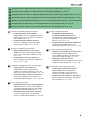
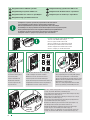
Premere il pulsante a cui si desidera associare l’indirizzo di chiamata
impostato tramite DIP-switch
Premere i pulsanti successivi per assegnare indirizzi consecutivi, ad ogni pressione l'indirizzo verrà incrementato di 1
Uscire dalla programmazione abbassando PRC Ripristinare la configurazione dei DIP-switch di S2
+2
=
2×
Press the button you want to associate with the call address set using the
DIP switches
Press the next buttons to assign consecutive addresses; every time a button is pressed the address will be increased by 1
Exit programming by moving PRC downwards
Restore the configuration of the DIP-switches for S2
Appuyer sur le bouton à associer à l’adresse d’appel définie par DIP switch
Appuyer sur les boutons l’un après l’autre pour attribuer les adresses consécutives. L’adresse augmente d’1 unité
chaque fois
que l’on appuie sur le bouton
Quitter la programmation en abaissant PRC
Rétablir la configuration des dip-switch de S2
Druk op de drukknop waaraan u het ingestelde oproepadres wilt koppelen
via DIP-switch
Druk op de opeenvolgende knoppen om opeenvolgende adressen toe te kennen, bij elke druk zal het adres met 1 toenemen.
Verlaat de programmering door PRC omlaag te zetten
Herstel de configuratie van de dip-switches van S2
Die Taste drücken, welcher die über Dipschalter eingestellte Rufadresse
zugeordnet werden soll
Drücken Sie die nächsten Tasten, um fortlaufende Adressen zuzuweisen. Bei jedem Drücken wird die Adresse um den Wert 1 erhöht
Verlassen Sie den Programmiermodus durch herunterschieben des
PRC-Schalters
Setzen Sie die Konfiguration der DIP-Schalter von S2 zurück
Presionar el pulsador al que se desea asociar la dirección de llamada
configurada mediante los DIP-switches
Presionar los pulsadores sucesivos para asignar las direcciones consecutivas; con cada pulsación, se aumenta de una unidad
Salir del modo programación bajando el PRC
Restablecer la configuración de los DIP-switches de S2
Premir o botão ao qual se pretende associar o endereço de chamada
configurado com o DIP switch
Premir os botões seguintes para atribuir endereços consecutivos. Cada pressão aumenta o endereço em 1
Sair da programação premindo PRC para baixo Repor a configuração dos DIP-switches S2
La page est en cours de chargement...

=
70
=
58
=
37
example code 37 example code 70 example code 58
7
6
8
11
25
=
5
Premere il pulsante a cui si desidera associare l’indirizzo di chiamata
impostato tramite DIP-switch
Ripetere le operazioni 4 e 5 per assegnare un indirizzo specifico a ciascun pulsante
Uscire dalla programmazione abbassando PRC Ripristinare la configurazione dei DIP-switch di S2
Press the button you want to associate with the call address set using the
DIP switches
Exit programming by moving PRC downwards
Repeat steps 4 and 5 to assign a specific address to each button
Restore the configuration of the DIP-switches for S2
Appuyer sur le bouton à associer à l’adresse d’appel définie par DIP switch
Quitter la programmation en abaissant PRC
Répéter les opérations 4 et 5 pour attribuer une adresse spécifique à chaque bouton
Rétablir la configuration des dip-switch de S2
Druk op de drukknop waaraan u het ingestelde oproepadres wilt koppelen
via DIP-switch
Verlaat de programmering door PRC omlaag te zetten
Ga naar de programmering door PRC omhoog te zetten
Herstel de configuratie van de dip-switches van S2
Die Taste drücken, welcher die über Dipschalter eingestellte Rufadresse
zugeordnet werden soll
Verlassen Sie den Programmiermodus durch herunterschieben des
PRC-Schalters
Wiederholen Sie die Schritte 4 und 5, um jeder Taste eine bestimmte Adresse zuzuweisen
Setzen Sie die Konfiguration der DIP-Schalter von S2 zurück
Presionar el pulsador al que se desea asociar la dirección de llamada
configurada mediante los DIP-switches
Salir del modo programación bajando el PRC
Repetir las operaciones 4 y 5 para asignar una dirección específica a cada pulsador
Restablecer la configuración de los DIP-switches de S2
Premir o botão ao qual se pretende associar o endereço de chamada
configurado com o DIP switch
Sair da programação premindo PRC para baixo
Repetir as operações 4 e 5 para associar um endereço específico a cada botão
Repor a configuração dos DIP-switches S2
La page est en cours de chargement...

1
2
1
1
1
1
2
6
4
1
1
CLACK!
2
CLACK!
5
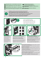
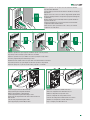
13
Selettore volume suoneria
Indicatore rosso: suoneria in modalità
silenziosa
Ringtone volume selector
Red indicator: ringtone in silent mode
Sélecteur volume sonnerie
Indicateur rouge : sonnerie en mode
silencieux
Keuzeschakelaar volumeregeling beltoon
Indicatielampje rood: oproeptoon in stille
modus
Lautstärkeregelung Läutewerk
Rote Anzeige: Klingelton stummgeschaltet
Selector del volumen del tono de llamada
Indicador rojo: tono de llamada en modo
silencio
Selector do volume da campainha
Indicador vermelho: campainha no modo
silencioso

Art. 1209
106 mm 62 mm
89 mm
14
È necessario installare a monte dell’impianto
videocitofonico un appropriato interruttore di rete
onnipolare con apertura del contatto di almeno 3mm.
• Togliere l’alimentazione prima di effettuare
qualsiasi operazione.
• Rimettere le protezioni sui morsetti.
• Non ostruire le aperture o fessure di ventilazione e
di dissipazione.
Programmazione indirizzo
Impostare l’indirizzo dell’appartamento (ad esempio: 37) tramite i DIP-
switch (vedi tabella pag 15)
example
code 37
Art. 2738W
Set the address of the apartment (for example: 37) using the DIP
switches (see table, page 15)
A suitable omnipolar switch with a contact opening
of at least 3mm must be installed upstream of the
video entry phone system.
• Disconnect the power supply before carrying out
any operations on the wiring.
• Replace the protections on the terminals.
• Do not obstruct the ventilation and cooling slots or
apertures.
Address programming
Définir l’adresse de l’appartement (par exemple : 37) au moyen des
DIP-switch (voir tableau page 15)
Installer un interrupteur de réseau omnipolaire avec
ouverture de contact d'au moins 3mm en amont de
l'installation vidéophonique.
• Couper l'alimentation avant d'effectuer toute
opération.
• Reposer les protections sur les bornes.
• Ne pas gêner les ouvertures ou les fentes
d'aération et de dissipation de la chaleur.
Programmation adresse
Stel het adres van het appartement (bijvoorbeeld: 37) via de DIP-
switches (zie tabel op pag 15)
Aan de basis van het video-deurintercomsysteem moet
een geschikte meerpolige netschakelaar zijn aangebracht
met een contactopening van ten minste 3mm.
• Sluit de voeding af voordat u
onderhoudswerkzaamheden uitvoert.
• Zet de beschermingen terug op de klemmen.
• Sluit de ventilatie-openingen of spleten voor de
warmte-afvoer niet af.
Programmering adres
Die Adresse der Wohnung (zum Beispiel : 37) über die Dipschalter
einstellen (siehe Tabelle auf Seite 15)
Vor der Video-Türsprechanlage muss ein allpoliger
Netzschalter mit einer Kontaktöffnung von
mindestens 3 mm installiert werden.
• Vor Eingriffen an der Anlage immer die
Spannungsversorgung unterbrechen.
• Die Schutzabdeckungen der Klemmen wieder
anbringen.
• Die Öffnungen und Schlitze zur Belüftung und
Wärmeableitung nicht verschließen.
Programmierung Adresse
Mediante los DIP-switches (véase tabla de pág. 15) configurar la
dirección de la vivienda (por ejemplo: 37)
Es necesario instalar, aguas arriba de la instalación de
videoportero, un interruptor de red omnipolar con una
distancia de apertura de los contactos de al menos 3 mm.
• Antes de efectuar cualquier operación hay que
cortar la alimentación.
• Colocar las protecciones en los bornes.
• No tapar las aberturas o ranuras de ventilación y
disipación.
Programación dirección
É necessário instalar a montante do equipamento
vídeo-intercomunicador um interruptor de rede
omnipolar adequado com uma abertura de contacto
de pelo menos 3 mm.
• Cortar a alimentação eléctrica antes de realizar
qualquer tipo de operação.
• Voltar a colocar as protecções nos bornes.
• Não obstruir as aberturas ou fendas de ventilação e
de dissipação de calor.
Programação endereço
Configurar o endereço do apartamento (por exemplo: 37) através dos DIP
switches (consultar a tabela na pág. 15)
La page est en cours de chargement...

B
A
A
C
B
2738W
MAX 4
CA2100P
CA9213
1209
CA2100P
CA9211
B
A
A
C
B
2738W
2738W
2738W
1209
A MAX B MAX C MAX
Comelit Art. 4577/4579 1 mm²
(Ø 1,2 mm AWG 17)
260 m
(850 feet)
130 m
(425 feet)
130 m
(425 feet)
UTP5 cat. 5 0,2 mm²
(Ø 0,5 mm AWG 24)
80 m
(260 feet)
40 m
(130 feet)
40 m
(130 feet)
0,28 mm² (Ø 0,6 mm AWG 23)
100 m
(328 feet)
50 m
(164 feet)
50 m
(164 feet)
0,5 mm² (Ø 0,8 mm AWG 20)
140 m
(460 feet)
70 m
(230 feet)
70 m
(230 feet)
1 mm² (Ø 1,2 mm AWG 17)
200 m
(656 feet)
100 m
(328 feet)
100 m
(328 feet)
1,5 mm² (Ø 1,4 mm AWG 15)
80 m
(260 feet)
40 m
(130 feet)
40 m
(130 feet)
UTP5 cat. 5 0,2 mm²
(Ø 0,5 mm AWG 24)
MULTI PAIR CABLE
GREEN
ORANGE
BLU
GREEN / WHITE
ORANGE / WHITE
BLU / WHITE
BROWN / WHITE
BROWN
260 m
(850 feet)
130 m
(425 feet)
130 m
(425 feet)
16
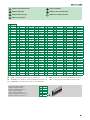
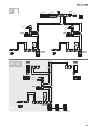
Distanze di funzionamento
Cavo UTP con connessione multi-
coppiola: RISPETTARE I COLORI
INDICATI IN FIGURA!
Operating distances
UTP cable with multi-cable
connection: FOLLOW THE COLOURS
SHOWN IN THE DIAGRAM!
Distances de fonctionnement
Câble UTP avec connexion paires
torsadées multiples : RESPECTER
LES COULEURS INDIQUÉES DANS
LA FIGURE !
Afstanden
UTP-kabel met multi-paar aansluiting:
DE IN DE AFBEELDING AANGEGEVEN
KLEUREN AANHOUDEN!
Maximal zulässige Entfernungen
UTP-Kabel mit Doppeladerbündel-
Anschluss: DIE IN DER ABBILDUNG
ANGEGEBENEN FARBEN BEACHTEN!
Distancias de funcionamiento
Cable UTP con conexión multipar:
¡RESPETAR LOS COLORES
INDICADOS EN LA FIGURA!
Distâncias de funcionamento
Cabo UTP com ligação multi-par:
RESPEITAR AS CORES INDICADAS
NA IMAGEM!

LL
O
D
E
T
R
NO
SE
-
SE
+
NC C
M
O
C
1209
L
N
110-240V
L2
L2
L1
L1
CA2100P
+ CA9213
31 Vdc
31 Vdc
1
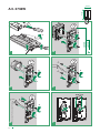
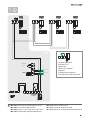
Chiamata fuori porta
Floor door call
Appel palier
Oproep van etagebel
Etagenruf
Llamada timbre de planta
Chamada da campainha externa
L L
C
F
P
C
F
P
2738W
1
ON
S1
1 2 3 4 6 75 8
L L
C
F
P
C
F
P
2738W
1
ON
S1
1 2 3 4 6 75 8
L L
C
F
P
C
F
P
2738W
1
ON
S1
1 2 3 4 6 75 8
L L
C
F
P
C
F
P
2738W
1
ON
S1
1 2 3 4 6 75 8
L L
C
F
P
C
F
P
Kit
17
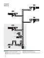
Max 20 m. Pulsante comando apriporta locale.
Max 20 m. Local door-opener button.
Max 20 m. Bouton commande ouvre-porte local.
Max 20 m. Bedieningsknop lokale deuropener.
Max 20 m. Lokale Türönertaste.
20 m máx. Pulsador abrepuertas local.
20 m máx
. Botão de comando abertura da porta local.

LL
O
D
E
T
R
NO
SE
-
SE
+
NC C
M
O
C
1209
L
N
110-240V
L2
L2
L1
L1
CA2100P
+ CA9211
1
2
3
4
4
2738W
1
3
ON
S1
1 2 3 4 6 75 8
4
2
L L
C
F
P
C
F
P
2738W
2738W
2738W
L L
C
F
P
C
F
P
L L
C
F
P
C
F
P
L L
C
F
P
C
F
P
ON
S1
1 2 3 4 6 75 8
ON
S1
1 2 3 4 6 75 8
ON
S1
1 2 3 4 6 75 8
Kit
18
Max 20 m. Pulsante comando apriporta locale.
Max 20 m. Local door-opener button.
Max 20 m. Bouton commande ouvre-porte local.
Max 20 m. Bedieningsknop lokale deuropener.
Max 20 m. Lokale Türönertaste.
20 m máx. Pulsador abrepuertas local.
20 m máx
. Botão de comando abertura da porta local.
La page est en cours de chargement...

www.comelitgroup.com
Via Don Arrigoni, 5 - 24020 Rovetta (BG) - Italy
2ª edizione 08/2019
cod. 2G40002446
CERTIFIED MANAGEMENT SYSTEMS
230 V
10A MAX
AC-DC
12V/24V
LL
O
D
E
T
R
SE
-
SE
+
NC
C
O
M
NO C
CA2100P
+CA921x
S2
JP1
SE
-
SE
+
NC NO C
P1
JP1
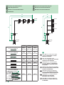
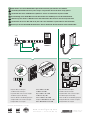
Attivazione del relè C.NC.NO della pulsantiera tramite pulsante P1 del citofono
Impostare JP1 come da figuraImpostare JP1 come da figura Settare il DIP 8 di S2 a ON
Activating C.NC.NO entrance panel relays using button P1 on the door-entry phone
Set JP1 as shown in the figureSet JP1 as shown in the figure
Set DIP8 for S2 to ON
Activation du relais C.NF.NO de la platine à travers le bouton P1 du poste audio
Programmer JP1 comme le montre la figure
Programmer JP1 comme le montre la figure Régler le DIP 8 de S2 sur ON
Inschakeling relais C.NC.NO van het deurstation via drukknop P1 van de deurtelefoon
Stel JP1 in volgens de afbeeldingStel JP1 in volgens de afbeelding Zet DIP 8 van S2 op ON
Aktivierung des Relais C.NC.NO an der Türstation über die Taste P1 der Innensprechstelle
Stellen Sie JP1 wie in der Abbildung gezeigt einStellen Sie JP1 wie in der Abbildung gezeigt ein
Stellen Sie DIP8 von S2 auf ON
Activación del relé C. NC. NA de la placa de calle mediante el pulsador P1 del telefonillo
Configurar JP1 como se ilustra en la figuraConfigurar JP1 como se ilustra en la figura
Configurar el DIP-switch 8 de S2 en ON
Activação do relé C.NC.NO da botoneira através do botão P1 do telefone intercomunicador
Configurar JP1 como na figuraConfigurar JP1 como na figura Definir oDIP-switch 8 de S2 em ON
-
 1
1
-
 2
2
-
 3
3
-
 4
4
-
 5
5
-
 6
6
-
 7
7
-
 8
8
-
 9
9
-
 10
10
-
 11
11
-
 12
12
-
 13
13
-
 14
14
-
 15
15
-
 16
16
-
 17
17
-
 18
18
-
 19
19
-
 20
20


Comelit KCA2061 Le manuel du propriétaire
- Taper
- Le manuel du propriétaire
- Ce manuel convient également à
dans d''autres langues
- italiano: Comelit KCA2061 Manuale del proprietario
- English: Comelit KCA2061 Owner's manual
- español: Comelit KCA2061 El manual del propietario
- Deutsch: Comelit KCA2061 Bedienungsanleitung
- Nederlands: Comelit KCA2061 de handleiding
- português: Comelit KCA2061 Manual do proprietário
Documents connexes
-
Comelit KCA2061 Technical Manual
-
-
-
-
-
-
Comelit 8451V Le manuel du propriétaire
-
-
-