Axis 0264-003 Manuel utilisateur
- Catégorie
- Des caméras de sécurité
- Taper
- Manuel utilisateur

ENGLISH FRANCAIS DEUTSCH ESPAÑOL
ITALIANO
AXIS 207
AXIS 207W
AXIS 207MW
Installation Guide


AXIS 207/207W/207MW Installation Guide Page 3
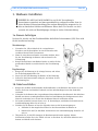
ENGLISH
ENGLISH
AXIS 207/207W/207MW
Installation Guide
This installation guide provides instructions for installing the AXIS 207/207W/207MW
Network Camera on your network. For all other aspects of using the product, please see the
User’s Manual, which is available on the CD included in this package, or from
www.axis.com/techsup
Installation steps
1. Check the package contents against the list below.
2. Hardware overview. Familiarize yourself with the camera. See page 4.
3. Install the hardware and make all cable connections. See page 7.
4. Set an IP address. See page 8.
5. Set the password. See page 12.
6. Configure the wireless connection. See page 13.
7. Adjust the focus. See page 15.
1. Package contents
Item Models/variants/notes
Network camera AXIS 207
AXIS 207W
AXIS 207MW
Indoor power supply
(country specific)
AXIS 207: type PS-L
AXIS 207MW/AXIS 207W: type PS-H
Power supply extension
cable
1.8 meters
Camera stand Supplied with 3 mounting screws. The extension section is ready fitted.
Flexible clamp For shelf mounting
Terminal block connector 4-pin connector block for connecting external devices to the I/O terminal con-
nector
Cable clip Self-adhesive - fixes to back panel for holding power cable
CD Axis Network Video Product CD, including installation tools and other software,
product documentation
Printed Materials AXIS 207/207W/207MW Installation Guide (this document)
Axis Warranty Document
Important!
This product must be used in
compliance with local laws
and regulations.

Page 4 AXIS 207/207W/207MW Installation Guide
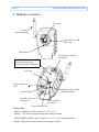
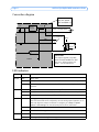
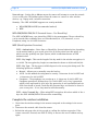
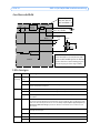
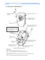
2. Hardware overview
Product ID & Serial number (S/N).
The serial number may be
required during the installation.
Dimensions
AXIS 207: HxWxD = 85 x 55 x 34mm (3.3" x 2.2" x 1.3")
Weight = 177g (0.39 lb) (stand included, power supply excluded)
AXIS 207W/MW: HxWxD = 85 x 55 x 40mm (3.3" x 2.2" x 1.6") (antenna excluded)
Weight: 190g (0.42 lb) (stand included, power supply excluded)
Network connector
(see page 5)
I/O terminal connector
(see page 5)
Power connector
(see page 5)
Focus ring
Status indicator LED
(outer ring)
Lock ring
Microphone
Antenna
(wireless models)
Network indicator
LED
Control button Wireless indicator LED
(wireless models)
Power indicator LED

AXIS 207/207W/207MW Installation Guide Page 5
ENGLISH
ENGLISH
Unit connectors
Network connector - RJ-45 Ethernet connector. Supports Auto-MDIX (AXIS 207W/MW
only) for automatic detection of straight or crossover cable. Using shielded cables is
recommended.
Power connector - Mini DC connector. 4.9-5.1V DC, max 4.0W. See product label for ±
connection.
I/O terminal connector - Used in applications for e.g. motion detection, event triggering,
time lapse recording, alarm notifications, etc. It provides the interface to:
• 1 transistor output - For connecting external devices such as relays and LED:s.
Connected devices can be activated by Output buttons on the Live View page or
by an Event Type. The output will show as active (in Event Configuration > Port
Status) if the alarm device is activated.
• 1 digital input - An alarm input for connecting devices that can toggle between
an open and closed circuit, for example: PIRs, door/window contacts, glass break
detectors, etc. When a signal is received the state changes and the input becomes
active (shown under Event Configuration > Port Status).
• Auxiliary power and GND
Function Pin number Notes Specifications
Transistor
Output
Pin 4 Uses an open-collector NPN
transistor with the emitter con-
nected to the GND pin. If used
with an external relay, a diode
must be connected in parallel
with the load, for protection
against voltage transients.
Max load = 100mA
Max voltage = 24V DC
(to the transistor)
Digital Input Pin 3 Connect to GND to activate, or
leave floating (or unconnected)
to deactivate.
Must not be exposed to
voltages greater than
10V DC
GND AXIS 207 = Pin 2
AXIS 207W/MW = Pin 1
Ground
Auxiliary DC
Power Input
AXIS 207 = Pin 1
AXIS 207W/MW = Pin 2
Electrically connected in parallel
with the connector for the power
supply, this pin provides an
auxiliary connector for mains
power to the unit.
This pin can also be used to
power auxiliary equipment, with
a maximum current of 50mA.
Voltage = 4.9-5.1V DC
(all models)
Min power:
AXIS 207: 2.5W
AXIS 207W: 3.5W
AXIS 207MW: 4.0W
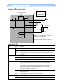
Pin layouts
1
4
1
4
AXIS 207MW
AXIS 207W
AXIS 207

Page 6 AXIS 207/207W/207MW Installation Guide
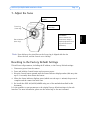
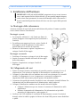
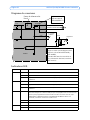
Connection diagram
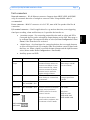
LED indicators
LED Color Indication
Wireless Unlit Wired mode.
Green Steady for connection to a wireless network. Flashes for network activity.
Red Steady for no wireless network connection. Flashes when scanning for wireless
networks.
Network Green Steady for connection to a 100 Mbit/s network. Flashes for network activity.
Amber Steady for connection to 10 Mbit/s network. Flashes for network activity.
Unlit No wired network connection, or AXIS 207MW/AXIS 207W in wireless mode.
Status Green Steady green for normal operation.
Note: The Status LED can be configured to be unlit during normal operation, or to
flash only when the camera is accessed. To configure, go to Setup > System
Options > LED settings. See the online help files for more information.
Amber Steady during startup, during reset to factory default or when restoring settings.
Red Slow flash for failed upgrade.
Power Green Normal operation.
Amber Flashes green/amber during firmware upgrade.
o
z
z
o
oo
oo
Camera
3.3V
Power - see table above.
e.g. pushbutton
Device
z
4
o3
o
Linear
Power
Supply
o
1
o
o
Relay
GND
+
2
Fuse
IMPORTANT!
This diagram applies to the AXIS
207W and AXIS 207MW. The AXIS
207 has a different pinout and
power - see the table above.
2
1
z
Fuse:
AXIS 207: 500mA
AXIS 207W/MW: 1A

AXIS 207/207W/207MW Installation Guide Page 7
ENGLISH
ENGLISH
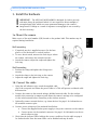
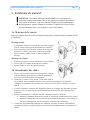
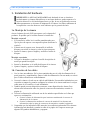
3. Install the hardware
3a. Mount the camera
Make a note of the serial number (S/N) located on the product label. This number may be
required during installation.
Wall mounting
1. If required, use the 3 supplied screws to fix the base
plate to a flat (horizontal or vertical) surface.
2. To use a shorter stand, unscrew the lock ring to release
the camera, and remove the extension section.
3. Attach the camera, adjust the angle and tighten the
lock ring.
Shelf mounting
1. Position the clamp and tighten the fixing screw
securely.
2. Attach the clamp to the lock ring on the camera.
3. Adjust the angle and tighten the lock ring.
3b. Connect the cables
1. Using the self-adhesive strip, attach the supplied cable
clip to the rear panel and fasten the power cable to it. This will prevent accidental cable
disconnection.
2. Connect the camera to the network using a shielded network cable. For the wireless
models, this connection is temporary and allows the camera’s settings to be configured
via the wired network before connecting to the wireless network.
3. Optionally connect external devices, e.g. alarm devices. See page 5 for information on
the terminal connector pins.
4. Connect power, using one of the methods listed below:
• Connect the supplied indoor power supply to the power connector on the camera.
• Connect power via the terminal connector. See page 5 for information on the ter-
minal connector pins.
5. Check that the indicator LED:s indicate the correct conditions. See the table on page 6
for further details. Note that some LED:s can be disabled and may be unlit.
!IMPORTANT! - The AXIS 207/207W/207MW is designed for indoor use only,
and must always be positioned where it is not exposed to direct sunlight or
strong halogen light, which can cause permanent damage to the camera’s
image sensor. Damage as a result of exposure to strong light is not covered by
the Axis warranty.

Page 8 AXIS 207/207W/207MW Installation Guide
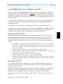
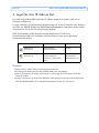
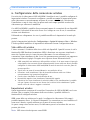
4. Set an IP address
To make it accessible on the network, the AXIS 207/207W/207MW must be assigned an IP
address.
Depending on the number of cameras you wish to install, the recommended method for
setting IP addresses in Windows is either AXIS IP Utility or AXIS Camera Management. Use
the method that best suits your purpose.
Both of these free applications are available on the Axis Network Video Product CD supplied
with this product, or they can be downloaded from www.axis.com/techsup
Notes:
• A network DHCP server is optional.
• The AXIS 207/207W/207MW has the default IP address 192.168.0.90
• If setting the IP address fails, check that there is no firewall blocking the operation.
• For other methods of setting or discovering the IP address of the AXIS 207/207W/207MW, e.g. in
other operating systems, see page 11.
Method Recommended for Operating system
AXIS IP Utility
See page 9.
Single cameras
Small installations
Windows
AXIS Camera Management
See page 10.
Multiple cameras
Large installations
Installations on other subnets
Windows 2000
Windows XP Pro
Windows 2003 Server

AXIS 207/207W/207MW Installation Guide Page 9
ENGLISH
ENGLISH
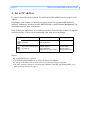
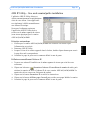
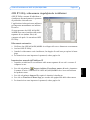
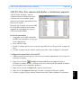
AXIS IP Utility - single camera/small installation
AXIS IP Utility automatically discovers
and displays Axis devices on your
network. The application can also be used
to manually set a static IP address.
Note that the computer running AXIS IP
Utility must be on the same network
segment (physical subnet) as the AXIS
207/207W/207MW.
Automatic discovery
1. Check that the AXIS 207/207W/
207MW is connected to the network
and that power has been applied.
2. Start AXIS IP Utility.
3. When the camera appears in the window, double-click it to open its home page.
4. See page 12 for instructions on how to set the password.
Set the IP address manually
1. Acquire an unused IP address on the same network segment your computer is connected
to.
2. Click the button Set IP address using serial number and enter the serial number
and IP address for the AXIS 207/207W/207MW. The serial number is located on the
product label.
3. Click the Set IP button and follow the instructions.
4. Click View Home Page button to access the camera’s web pages.
5. See page 12 for instructions on how to set the password.

Page 10 AXIS 207/207W/207MW Installation Guide
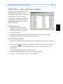
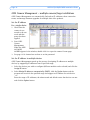
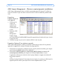
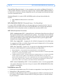
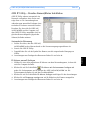
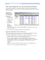
AXIS Camera Management - multiple cameras/large installations
AXIS Camera Management can automatically find and set IP addresses, show connection
status, and manage firmware upgrades for multiple Axis video products.
Set the IP address
for a single device
1. Check that the
camera is con-
nected to the net-
work and that
power has been
applied.
2. Start AXIS
Camera
Management.
When the AXIS
207/207W/
207MW appears in the window, double-click it to open the camera’s home page.
3. See page 12 for instructions on how to set the password.
Set the IP address in multiple devices
AXIS Camera Management speeds up the process of assigning IP addresses to multiple
devices, by suggesting IP addresses from a specified range.
1. Select the devices you wish to configure (different models can be selected) and click the
Assign IP button.
2. Select Obtain IP addresses automatically (DHCP), click the Update button and the
program will search in the specified range and suggest an IP address for each device.
-or-
Enter the range of IP addresses, the subnet mask and default router that devices can use
and click the Update button.

AXIS 207/207W/207MW Installation Guide Page 11
ENGLISH
ENGLISH
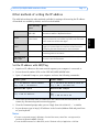
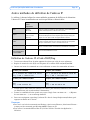
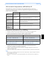
Other methods of setting the IP address
The table below shows the other methods available for setting or discovering the IP address.
All methods are enabled by default, and all can be disabled.
Set the IP address with ARP/Ping
1. Acquire an IP address on the same network segment your computer is connected to.
2. Locate the serial number (S/N) on the AXIS 207/207W/207MW label.
3. Open a Command Prompt on your computer and enter the following commands:
4. Check that the network cable is connected to the camera and then start/restart the
camera, by disconnecting and reconnecting power.
5. Close the Command prompt when you see ‘Reply from 192.168.0.125: ...’ or similar.
6. In your browser, type in http://<IP address> in the Location/Address field and press Enter
on your keyboard.
Notes:
• To open a command prompt in Windows: from the Start menu, select Run... and type cmd (or
command in Windows 98/ME). Click OK.
• To use the ARP command on a Mac OS X, use the Terminal utility in Application > Utilities.
Use in operating
system
Notes
UPnP™
Windows
(ME or XP)
When enabled on your computer, the camera is automatically
detected and added to “My Network Places.”
Bonjour MAC OSX
(10.4 or later)
Applicable to browsers with support for Bonjour. Navigate to the
Bonjour bookmark in your browser (e.g. Safari) and click on the
link to access the camera’s web pages.
AXIS Dynamic DNS
Service
All A free service from Axis that allows you to quickly and simply
install your camera. Requires an Internet connection with no
HTTP proxy. See www.axiscam.net for more information.
ARP/Ping All See below. The command must be issued within 2 minutes of
connecting power to the camera.
View DHCP server
admin pages
All To view the admin pages for the network DHCP server, please see
the server’s own documentation.
Windows syntax Windows example
arp -s <IP Address> <Serial Number>
ping -l 408 -t <IP Address> arp -s 192.168.0.125 00-40-8c-18-10-00
ping -l 408 -t 192.168.0.125
UNIX/Linux/Mac syntax UNIX/Linux/Mac example
arp -s <IP Address> <Serial Number> temp
ping -s 408 <IP Address> arp -s 192.168.0.125 00:40:8c:18:10:00
temp
ping -s 408 192.168.0.125

Page 12 AXIS 207/207W/207MW Installation Guide
5. Set the password
When accessing the AXIS 207/207W/207MW
for the first time, the ‘Configure Root
Password’ dialog will be displayed.
1. Enter a password and then re-enter it, to
confirm the spelling. Click OK.
2. Enter the user name root in the ‘Enter
Network Password’ dialog.
Note: The default administrator user name
root cannot be deleted.
3. Enter the password as set above, and click OK. If the password is lost, the AXIS 207/
207W/207MW must be reset to the factory default settings. See page 15.
4. If required, click Yes to install AMC (AXIS Media Control), which allows viewing of the
video stream in Internet Explorer. You will need administrator rights on the computer to
do this.
The Live View page of the AXIS 207/207W/207MW is displayed, with links to the Setup
tools, which allow you to customize the camera.
Setup - Provides all the neces-
sary tools for configuring the
camera to requirements.
Help - Displays online help on
all aspects of using the camera.

AXIS 207/207W/207MW Installation Guide Page 13
ENGLISH
ENGLISH
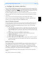
6. Configure the wireless connection
Once the AXIS 207W/MW has been installed on your network, the wireless settings can be
configured. These settings should always (i.e. both during installation and at all other times)
be configured or changed in the camera first and in the wireless access point secondly. This
ensures that the camera is always accessible when making changes.
The AXIS 207W/MW automatically senses the available network connections, and allows
only one of these to be active at a time. Connecting a network cable disables the wireless
connection.
Using a wired connection ensures greater secrecy while making these settings.
Open the wireless settings from Setup > System Options > Network > Wireless. These
settings can also be reached from the Basic Configuration menu.
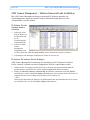
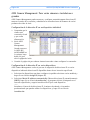
Status of Wireless Networks
This list is the result of a network scan. Access points with a disabled SSID Broadcast will
not appear unless the camera is associated with it. The network currently associated to is
shown in blue. A network using unsupported security is shown in grey. The following
information is provided:
• SSID - The name of a wireless network (or ad-hoc device). If the same name occurs
several times this means that several access points for that network were found. The
AXIS 207W/MW cannot be configured to only associate with one particular access
point.
• Network Type - An Access Point (Master) or Ad-Hoc device.
• Security - Shows which type of security the network uses. See below for the
supported security types.
• Channel - Shows the wireless channel currently in use.
• Signal strength - Shows the signal strength.
• Bit rate - Shows the bit rate in Mbit/s. This can only be shown for the access point
currently in use. Note that the bit rate shown is the current rate, and that this value
may vary over time.
Wireless Settings
These settings control how the AXIS 207W/MW interacts with the wireless network. Apart
from identifying the wireless network, it is also possible to enable wireless encryption.
SSID - This is the name of the wireless network the camera is configured for. The field
accepts up to 32 alphanumeric characters. The name must be exactly the same as that used
in the wireless access point, or the connection will not be established.
Leaving this field blank means the camera will attempt to access the nearest unsecured
network.
Note: SSID is sometimes written as ESSID.

Page 14 AXIS 207/207W/207MW Installation Guide
Network type - Setting this to Master means the camera will attempt to access the network
via an access point. The Ad-hoc option allows the camera to connect to other wireless
devices, e.g. a laptop with a wireless connection.
Security - The AXIS 207W/MW supports two security methods:
•WPA-PSK/WPA2-PSK (recommended method)
•WEP
WPA-PSK/WPA2-PSK (Wi-Fi Protected Access - Pre-Shared Key)
The AXIS 207W/MW uses a pre-shared key (PSK) for key management. The pre-shared key
can be entered either as Manual hex, as 64 hexadecimal (0-9, A-F) characters, or as a
Passphrase, using 8 to 63 ASCII characters.
WEP (Wired Equivalent Protection)
WEP - Authentication - Select Open or Shared Key System Authentication, depending
on the method used by your access point. Not all access points have this option, in
which case they probably use Open System, which is sometimes known as SSID
Authentication.
WEP - Key length - This sets the length of the key used for the wireless encryption, 64
or 128 bit. The encryption key length can sometimes be shown as 40/64 and 104/128.
WEP - Key Type - The key types available depend on the access point being used. The
following options are available:
• Manual - Allows you to manually enter the hex key.
• ASCII - In this method the string must be exactly 5 characters for 64-bit WEP and
13 characters for 128-bit WEP.
• Passphrase - The passphrase can contain up to 31 characters. In 64-bit WEP, the
Passphrase generates 4 different keys. For 128-bit WEP, only 1 key is generated,
which is then replicated for all 4 keys. Key generation is not standardized and can
differ from brand to brand. Check that the generated keys are identical to those in
your access point - if not, they must be entered manually.
WEP - Active Transmit Key - When using WEP encryption, this selects which of the 4
keys the AXIS 207MW/AXIS 207W uses when transmitting.
Complete the wireless installation
1. Check that the wireless settings in the camera correspond to the settings in the access
point.
2. Disconnect the network cable from the camera.
3. Refresh the web page after 20-30 seconds to confirm the wireless connection. If the
camera cannot be accessed, run AXIS IP Utility to discover the new IP address and try
again.

AXIS 207/207W/207MW Installation Guide Page 15
ENGLISH
ENGLISH
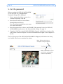
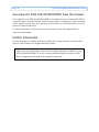
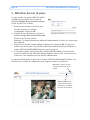
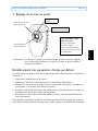
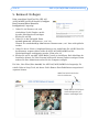
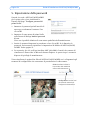
7. Adjust the focus
Resetting to the Factory Default Settings
This will reset all parameters, including the IP address, to the Factory Default settings:
1. Disconnect power from the camera.
2. Press and hold the Control button and reconnect power.
3. Keep the Control button pressed until the Status indicator displays amber (this may take
up to 15 seconds), then release the button.
4. When the Status indicator displays green (which can take up to 1 minute) the process is
complete and the camera has been reset.
5. Re-install the AXIS 207/207W/207MW using one of the methods described in this
document.
It is also possible to reset parameters to the original factory default settings via the web
interface. For more information, please see the online help or the user’s manual.
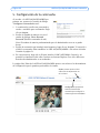
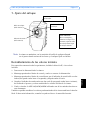
To focus:
Open a browser and
examine the image. If
required, adjust the focus
ring until the focus is
satisfactory.
Small dot above the lens
assembly.
Note: Upon delivery, the raised line on the focus ring is aligned with the dot
above the lens, and the focus is set to infinity.
Raised line on
focus ring.
Status indicator
(outer ring)
Focus ring
(inner ring)

Page 16 AXIS 207/207W/207MW Installation Guide
Accessing the AXIS 207/207W/207MW from the Internet
Once installed, your AXIS 207/207W/207MW is accessible on your local network (LAN). To
access the camera from the Internet, network routers must be configured to allow incoming
traffic, which is usually done on a specific port. Please refer to the documentation for your
router for further instructions.
For more information on this and other topics, please visit the Axis Support Web at
www.axis.com/techsup
Further information
The user’s manual is available from the Axis Web site at www.axis.com or from the Axis
Network Video Product CD supplied with this product.
Tip!
Visit www.axis.com/techsup to check if there is updated firmware available for your
AXIS 207/207W/207MW. To see the currently installed firmware version, see the
Basic Configuration web page in the product’s setup tools.

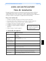
AXIS 207/207W/207MW Guide d’installation Page 17
FRANCAIS
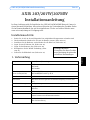
AXIS 207/207W/207MW
Guide d'installation
Ce guide d'installation vous explique comment installer la AXIS 207/207W/207MW Network
Camera sur votre réseau. Pour d'autres informations sur l'utilisation de ce produit, consultez
le Manuel de l'utilisateur, disponible sur le CD fourni, ou visitez le site www.axis.com/
techsup.
Étapes de l'installation
1. Vérifiez le contenu de la livraison à l'aide de la liste ci-dessous.
2. Présentation du matériel. Familiarisez-vous avec la caméra. Reportez-vous à la page 18.
3. Installez le matériel et connectez tous les câbles. Reportez-vous à la page 21.
4. Paramétrez une adresse IP. Reportez-vous à la page 22.
5. Définissez le mot de passe. Reportez-vous à la
page 26.
6. Configurez la connexion sans fil. Reportez-vous à la
page 27.
7. Réglez la mise au point. Reportez-vous à la page 29.
1. Contenu de l'emballage
Article Modèles/variantes/remarques
Caméra réseau AXIS 207
AXIS 207W
AXIS 207MW
Alimentation intérieure
(dépend du pays)
AXIS 207 : type PS-L
AXIS 207MW/AXIS 207W : type PS-H
Câble de rallonge
d'alimentation
1,8 mètres
Pied de la caméra Fourni avec 3 vis de montage. La section télescopique est déjà montée.
Pince flexible Utilisée pour le montage sur étagère
Connecteur pour terminaux Connecteur 4 broches pour la connexion d'équipements externes au connecteur
E/S
Clip pour câble Auto-adhésif : sert à immobiliser le câble d'alimentation au niveau de la face
arrière
CD CD de la caméra vidéo réseau Axis comprenant les outils d'installation, les
autres logiciels et la documentation
Documentation imprimée AXIS 207/207W/207MW Guide d'installation (le présent document)
Document de garantie d'Axis
Important !
Ce produit doit être utilisé
conformément aux lois et
dispositions locales en
vigueur.

Page 18 AXIS 207/207W/207MW Guide d’installation
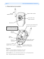
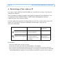
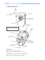
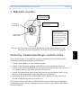
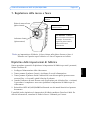
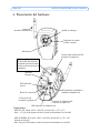
2. Présentation du matériel
Microphone
Dimensions
AXIS 207 : H x L x P = 85 x 55 x 34 mm (3,3" x 2,2" x 1,3")
Poids = 177 g (0,39 lb) (pied inclus, alimentation exclue)
AXIS 207W/MW : H x L x P = 85 x 55 x 40 mm (3,3" x 2,2" x 1,6") (antenne exclue)
Poids : 190 g (0,42 lb) (pied inclus, alimentation exclue)
Connecteur de réseau
(reportez-vous à la page 19)
Connecteur pour terminaux E/S
(reportez-vous à la page 19)
Connecteur d'alimentation
(reportez-vous à la page 19)
Bague de mise au point
Témoin DEL d’état
(bague extérieure)
(modèles sans fil)
Bague de
blocage
Antenne
ID du produit et numéro de série
(S/N). Le numéro de série peut
être requis pendant l'installation.
Témoin
DEL réseau
Bouton de
commande
Témoin DEL
d’alimentation
Témoin DEL sans fil
(modèles sans fil)

AXIS 207/207W/207MW Guide d’installation Page 19
FRANCAIS
Connecteurs de l'unité
Connecteur de réseau - Connecteur Ethernet RJ-45. Prend en charge Auto-MDIX (AXIS
207W/MW uniquement) pour la détection automatique de câble direct ou inverseur. Il est
recommandé d'utiliser des câbles blindés.
Connecteur - Miniconnecteur CC. 4,9-5,1 V CC, jusqu'à 4,0 W. Reportez-vous à l'étiquette
du produit pour connaître la connexion ±.
Connecteur pour terminaux E/S - Utilisé dans les applications, par exemple pour la
détection de mouvement, le déclenchement d'événements, l'enregistrement à intervalles, les
notifications d'alarme, etc. Il sert d'interface aux éléments suivants :
• 1 sortie transistor : permet de connecter des dispositifs externes, comme des relais ou DELs.
Les dispositifs connectés peuvent être activés à l'aide des boutons de sortie sur la page Live
View (Vidéo en direct) ou à l'aide d'un type d'événement. La sortie est considérée comme
étant active (Event Configuration (Configuration d'événement) > Port Status (État du
port)) si le dispositif d'alarme est activé.
• 1 entrée numérique : entrée d'alarme utilisée pour connecter des dispositifs pouvant passer
d'un circuit ouvert à un circuit fermé, par exemple : les détecteurs infrarouge passifs, les
contacts de porte/fenêtre, les détecteurs de bris de verre, etc. Lorsqu'un signal est reçu,
l'état change et l'entrée devient active (elle apparaît sous Event Configuration
(Configuration d'événement) > Port Status (État du port)).
•Alimentation auxiliaire et mise à la terre
Fonction Numéro de broche Remarques Spécifications
Sortie
transistor
Broche 4 Utilise un transistor NPN à collecteur
ouvert avec émetteur connecté au
contact à la masse. En cas d'utilisation
avec un relais externe, une diode doit
être connectée en parallèle avec la
charge, comme protection contre les
tensions transitoires.
Charge maximale = 100 mA
Tension maximale = 24 VCC
(en entrée)
Entrée
numérique
Broche 3 Connectez-la au GND pour l'activer ou
laissez-la flotter (ou déconnectée)
pour la désactiver.
Ne doit pas être exposée à
une tension supérieure à 10
V CC
GND AXIS 207 = broche 2
AXIS 207W/MW = broche 1
Terre
Entrée
d'alimentation
CC auxiliaire
AXIS 207 = broche 1
AXIS 207W/MW = broche 2
Branchée en parallèle au connecteur
de l'alimentation PS-H, cette broche
fournit à l'unité un connecteur
auxiliaire pour l'alimentation secteur.
Cette broche peut également servir à
alimenter le matériel auxiliaire
(intensité maximale : 50 mA).
Tension = 4,9-5,1 V CC
(tous les modèles)
Alimentation minimale :
AXIS 207 : 2,5 W
AXIS 207W : 3,5 W
AXIS 207MW : 4,0 W
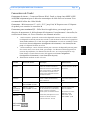
Disposition des broches
1
4
1
4
AXIS 207MW
AXIS 207W
AXIS 207

Page 20 AXIS 207/207W/207MW Guide d’installation
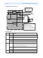
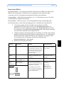
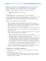
Diagramme de connexion
Témoins DEL
DEL Couleur Indication
Module Éteint Mode avec fil.
Vert Continu en cas de connexion à un réseau sans fil. Clignote en cas d'activité réseau.
Rouge Continu en l'absence de connexion à un réseau sans fil. Clignote lors de la recherche de réseaux
sans fil.
Réseau Vert Continu en cas de connexion à un réseau 100 Mbits/s. Clignote en cas d'activité réseau.
Orange Continu en cas de connexion à un réseau 10 Mbits/s. Clignote en cas d'activité réseau.
Éteint Pas de connexion à un réseau avec fil ou AXIS 207MW/AXIS 207W en mode sans fil.
État Vert Vert continu en cas de fonctionnement normal.
Remarque : Le voyant d'état peut être configuré pour être éteint au cours du fonctionnement
normal, ou pour clignoter uniquement lors des accès à la caméra. Pour ce faire, cliquez sur
Setup > System Options > LED settings (Configuration > Options système > Paramètres DEL).
Reportez-vous à l'aide en ligne pour plus d'informations.
Orange En continu pendant le démarrage, la réinitialisation des valeurs d'usine ou la restauration des
paramètres.
Rouge Clignote lentement en cas d'échec de la mise à niveau.
Alimen-
tation
Vert Fonctionnement normal.
Orange Clignote en vert/orange pendant la mise à niveau du microprogramme.
o
z
z
o
oo
oo
Caméra
3,3 V
Alimentation (reportez
-vous au tableau précédent)
par exemple, un bouton de commande
Dispositif
z
4
o3
o
Alimen
-tation
linéaire
o
1
o
o
Relais
GND
+
2
Fusible
IMPORTANT!
Ce diagramme s'applique aux caméras
AXIS 207W et AXIS 207MW.
La caméra AXIS 207 présente une
alimentation et un brochage différents
(reportez-vous au tableau précédent).
2
1
z
Fusible :
AXIS 207 : 500 mA
AXIS 207W/MW : 1 A
La page est en cours de chargement...
La page est en cours de chargement...
La page est en cours de chargement...
La page est en cours de chargement...
La page est en cours de chargement...
La page est en cours de chargement...
La page est en cours de chargement...
La page est en cours de chargement...
La page est en cours de chargement...
La page est en cours de chargement...
La page est en cours de chargement...
La page est en cours de chargement...
La page est en cours de chargement...
La page est en cours de chargement...
La page est en cours de chargement...
La page est en cours de chargement...
La page est en cours de chargement...
La page est en cours de chargement...
La page est en cours de chargement...
La page est en cours de chargement...
La page est en cours de chargement...
La page est en cours de chargement...
La page est en cours de chargement...
La page est en cours de chargement...
La page est en cours de chargement...
La page est en cours de chargement...
La page est en cours de chargement...
La page est en cours de chargement...
La page est en cours de chargement...
La page est en cours de chargement...
La page est en cours de chargement...
La page est en cours de chargement...
La page est en cours de chargement...
La page est en cours de chargement...
La page est en cours de chargement...
La page est en cours de chargement...
La page est en cours de chargement...
La page est en cours de chargement...
La page est en cours de chargement...
La page est en cours de chargement...
La page est en cours de chargement...
La page est en cours de chargement...
La page est en cours de chargement...
La page est en cours de chargement...
La page est en cours de chargement...
La page est en cours de chargement...
La page est en cours de chargement...
La page est en cours de chargement...
La page est en cours de chargement...
La page est en cours de chargement...
La page est en cours de chargement...
La page est en cours de chargement...
La page est en cours de chargement...
-
 1
1
-
 2
2
-
 3
3
-
 4
4
-
 5
5
-
 6
6
-
 7
7
-
 8
8
-
 9
9
-
 10
10
-
 11
11
-
 12
12
-
 13
13
-
 14
14
-
 15
15
-
 16
16
-
 17
17
-
 18
18
-
 19
19
-
 20
20
-
 21
21
-
 22
22
-
 23
23
-
 24
24
-
 25
25
-
 26
26
-
 27
27
-
 28
28
-
 29
29
-
 30
30
-
 31
31
-
 32
32
-
 33
33
-
 34
34
-
 35
35
-
 36
36
-
 37
37
-
 38
38
-
 39
39
-
 40
40
-
 41
41
-
 42
42
-
 43
43
-
 44
44
-
 45
45
-
 46
46
-
 47
47
-
 48
48
-
 49
49
-
 50
50
-
 51
51
-
 52
52
-
 53
53
-
 54
54
-
 55
55
-
 56
56
-
 57
57
-
 58
58
-
 59
59
-
 60
60
-
 61
61
-
 62
62
-
 63
63
-
 64
64
-
 65
65
-
 66
66
-
 67
67
-
 68
68
-
 69
69
-
 70
70
-
 71
71
-
 72
72
-
 73
73


Axis 0264-003 Manuel utilisateur
- Catégorie
- Des caméras de sécurité
- Taper
- Manuel utilisateur
dans d''autres langues
- italiano: Axis 0264-003 Manuale utente
- English: Axis 0264-003 User manual
- español: Axis 0264-003 Manual de usuario
- Deutsch: Axis 0264-003 Benutzerhandbuch