Senco DS530 Series Manuel utilisateur
- Catégorie
- Outils électroportatifs
- Taper
- Manuel utilisateur

KYOCERA-SENCO Industrial Tools, Inc.
8450 Broadwell Road
Cincinnati, OH 45244
1-800-543-4596
www.senco.com © 2022 by KYOCERA-SENCO Industrial Tools, Inc.
NFD810X • Issued May 18, 2022 (Replaces 6/13/2021)
DS530 Series
AUTO-FEED SCREW
SYSTEM ATTACHMENT
Operating Instructions
IMPORTANT:
Read before use.

Table of Contents
General Power Tool Safety Warnings ...................................................................................... 4
Work Area Safety ................................................................................................................... 4
Electrical Safety ..................................................................................................................... 4
Personal Safety ..................................................................................................................... 4
Power Tool Use and Care ...................................................................................................... 5
Service .................................................................................................................................. 5
Functional Description ............................................................................................................. 6
Tool Operation .......................................................................................................................... 7
Installing a DS530 Attachment .............................................................................................. 7
Adjusting for Fastener Length ............................................................................................... 8
Loading the Tool .................................................................................................................... 9
Depth of Drive Adjustment .................................................................................................... 9
Driving Screws ...................................................................................................................... 9
Reverse Operation ............................................................................................................... 10
Bit Replacement .................................................................................................................. 10
Nosepiece Replacement ...................................................................................................... 10
Installing the Extension Pole ............................................................................................... 11
Maintenance .......................................................................................................................... 12
Accessories ............................................................................................................................ 12
Technical Specifications ........................................................................................................ 12
Troubleshooting ..................................................................................................................... 13
2

3
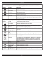
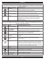
SYMBOLS
The following signal words and meanings are intended to explain the levels of risk associated
with this product.
SYMBOL SIGNAL MEANING
DANGER: Indicates a hazardous situation, which, if not avoided, will result in
death or serious injury.
WARNING: Indicates a hazardous situation, which, if not avoided, could result in
death or serious injury.
CAUTION: Indicates a hazardous situation, which, if not avoided, may result in
minor or moderate injury.
NOTICE: (Without Safety Alert Symbol) indicates information considered im-
portant, but not related to a potential injury (e.g. messages relating
to property damage).
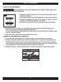
Some of the following symbols may be used on this product. Please study them and learn their meaning.
Proper interpretation of these symbols will allow you to operate the product in a better, safer manner.
SYMBOL NAME DESIGNATION/EXPLANATION
Safety Alert Indicates a potential personal injury hazard.
Read Operator’s
Manual
To reduce the risk of injury, user must read and understand opera-
tor’s manual before using this product.
Eye Protection Always wear eye protection with side shields marked to comply with
ANSI Z87.1.
Wet Conditions
Alert
Do not expose to rain or use in damp locations.
No Hands Failure to keep your hands away from blade will result in serious
personal injury.
Recycle This product uses Litium-ion batteries. Local, state, or federal laws
may prohibit disposal of batteries in ordinary trash. Consult your
local waste authority for information regarding available recycling
and or disposal options.
VVolts Voltage
min Minutes Time
Direct Current Type or characteristic of current
Alternating
Current
Type or characteristic of current
noNo Load Speed Rotational speed, at no load
.../min Per Minute Revolutions, strokes, surface speed, orbits, etc. per minute

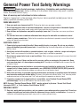
General Power Tool Safety Warnings
WARNING
Read all safety warnings, instructions, illustrations and specifications pro-
vided with this power tool. Failure to follow all instructions listed below may result in electric
shock, fire and/or serious injury.
Save all warnings and instructions for future reference.
The term “power tool” in the warnings refers to your mains-operated (corded) power tool or
battery-operated (cordless) power tool.
WORK AREA SAFETY
1. Keep your work area clean and well lit. Cluttered or dark areas promote accidents.
2. Do not operate power tools in explosive atmospheres, such as in the presence of flammable liquids,
gases, or dust. Power tools create sparks which may ignite the dust or fumes.
3. Keep children and bystanders away while operating a power tool. Distractions can cause you to lose
control.
4. The included auto-feed screwdriver attachment was designed to work with one make and several
models of power screwdrivers. Refer to the screwdriver manufacturer’s operator’s manual for related
safety and operating instructions.
ELECTRICAL SAFETY
5. Power tool plugs must match the outlet. Never modify the plug in any way. Do not use any adapter
plugs with earthed (grounded) power tools. Unmodified plugs and matching outlets will reduce risk of
electric shock.
6. Avoid body contact with earthed or grounded surfaces, such as pipes, radiators, ranges and refrigera-
tors. There is an increased risk of electric shock if your body is earthed or grounded.
7. Do not expose power tools to rain or wet conditions. Water entering a power tool will increase the risk of
electric shock.
8. Do not abuse the cord. Never use the cord for carrying, pulling or unplugging the power tool. Keep
cord away from heat, oil, sharp edges or moving parts. Damaged or entangled cords increase the risk
of electric shock.
9. When operating a power tool outdoors, use an extension cord suitable for outdoor use. If operating
a power tool in a damp location is unavoidable, use a RESIDUAL CURRENT DEVICE (RCD) protected
supply. Use of a cord suitable for outdoor use reduces the risk of electric shock.
10. Hold power tool using its insulated gripping surfaces when performing an operation where the fastener
may come into contact with hidden wiring. Fasteners that come into contact with a “live” wire may make
exposed metal parts of the power tool “live” and could give the operator an electric shock.
11. If operating a power tool in damp location is unavoidable, use a Residual Current Devise (RCD)
protected supply. Use of an RCD reduces the risk of electric shock.
NOTE: the term “Residual Current Devise (RCD)” may be replaced by the term “Ground Fault Circuit
Interrupter (GFCI)” or “Earth Leakage Circuit Breaker (ELCB)”.
PERSONAL SAFETY
12. Stay alert, watch what you are doing, and use common sense when operating a power tool. Do not use
a power tool while you are tired or under the influence of drugs, alcohol, or medication. A moment of
inattention while operating power tools may result in serious personal injury.
4

13. Use personal protective equipment. Always wear eye protection. Protective equipment such as dust
mask, non-skid safety shoes, hard hat or hearing protection used for appropriate conditions will reduce
personal injuries.
14. Prevent unintentional starting. Ensure the switch is in the off-position before connecting to power
source and/or battery pack, picking up or carrying the tool. Carrying power tools with your finger on the
switch or energizing power tools that have the switch on promotes accidents.
15. Remove any adjusting key or wrench before turning the power tool on. A wrench or a key left attached to
a rotating part of the power tool may result in personal injury.
16. Do not overreach. Keep proper footing and balance at all times. This enables better control of the power
tool in unexpected situations.
17. Dress properly. Do not wear loose clothing or jewelry. Keep your hair and clothing away from moving
parts. Loose clothes, jewelry or long hair can be caught in moving parts.
18. If devices are provided for dust extraction and collection, ensure these are connected and properly
used. Use of dust collection can reduce dust-related hazards.
19. Do not let familiarity gained from frequent use of tools allow you to become complacent and ignore tool
safety principles. A careless action can cause severe injury within a fraction of a second.
POWER TOOL USE AND CARE
20. Do not force the power tool. Use the correct power tool for your application. The correct power tool will
provide better safer results when used according to its specifications.
21. Do not use the power tool if the power switch does not turn it on and off. Any power tool that cannot be
controlled with the switch is dangerous and must be repaired.
22. Disconnect the plug from the power source and/or remove the BATTERY pack, if detachable, from the
power tool before making any adjustments, changing accessories, or storing power tools.
Such preventive safety measures reduce the risk of starting the power tool accidentally.
23. Store idle power tools out of the reach of children and do not allow persons unfamiliar with the power
tool or these instructions to operate the power tool. Power tools are dangerous in the hands of untrained
users.
24. Maintain power tools and accessories. Check for misalignment or binding of moving parts, breakage of
parts and any other condition that may affect the power tool’s operation. If damaged, have the power
tool repaired before use. Many accidents are caused by poorly maintained power tools.
25. Keep cutting tools sharp and clean. Properly maintained cutting tools with sharp cutting edges are less
likely to bind and are easier to control.
26. Use the power tool, accessories and tool bits etc. in accordance with these instructions, taking into
account the working conditions and the work to be performed. Use of the power tool for operations
different from its intended purpose could result in a hazardous situation.
27. Keep handles and grasping surfaces dry, clean and free from oil and grease. Slippery handles and
grasping surfaces do not allow for safe handling and control of the tool in unexpected situations.
SERVICE
28. Have your power tool serviced by a qualified repair person using only identical replacement parts.
This will ensure that the safety of the power tool is maintained.
29. Users or full-service dealers need to be aware that a spring is housed inside the feed system.
It will release from its constrained position during disassembly. Normal precautions should apply.
GENERAL POWER TOOL SAFETY WARNINGS
5

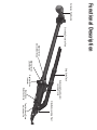
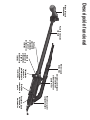
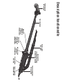
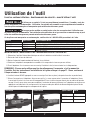
Functional Description
Extension Pole Handle
Stand-Up Extension Pole Strip Guide Track
Detachable Feed System
Locking Clamp
Slide Body Loading Point
Tool-less Nose Piece
Adjustment Pin
Nose Piece
Retention Screw
Depth of Drive
Indicator
Depth of Drive
Lock Button
Depth of Drive
Adjustment Knob

Tool Operation
Read sections titled “Safety Warnings” before operating tool.
WARNING
Do not use this product if it is not completely assembled or if any parts
appear to be missing or damaged. Use of a product that is not properly and completely
assembled or with damaged or missing parts could result in serious personal injury.
WARNING
Do not attempt to modify this product or create accessories or attachments not
recommended for use with this product. Any such alteration or modification is misuse
and could result in hazardous conditions possibly leading to serious personal injury.
If any parts are damaged or missing, please call 1-800-543-4596 for assistance.
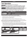
MODEL ADAPTER COMPATIBLE TOOLS
DS530-S1 MB0184 SENCO • SG2510, SG4100
DS530-M1 MB0186 MAKITA • FS2200, FS2500, FS4200, FS6200, XSF03, XSF04, XSF05
DS530-D1 MB0183 DEWALT • DCF624
MB0185 DEWALT • DW252, DW253, DW255, DW257, DW266, DW272, DW276
SOLD SEPARATELY MB0187 MAKITA • FS2701
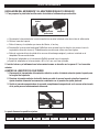
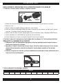
INSTALLING A DS530-S1 OR DS530-M1 ADAPTER AND ATTACHMENT
1. Unplug tool from electrical supply or remove battery before installing attachment.
2. Remove the manufacturer’s nose cone from the tool.
3. Remove manufacturer’s bit and holder if present.
4. Choose the adapter which matches the screwdriver model and brand you are using.
5. Attach the adapter onto the screwdriver ensuring it is fully seated and secure, tighten all set screws.
NOTE: If you want to use an extension pole with the attachment, install that, now. See instructions for
using the extension pole on page 11. Otherwise, continue to next step, below.
6. Install the appropriate Senco bit, making sure it is fully seated (this may require some force.)
7. Slide the attachment onto the adapter. Make sure there’s no gap between the attachment and the adapter.
Tighten clamp. Adjust the screw with a 2.5mm hex key if necessary to provide more or less clamping
force. This should only be tightened enough to prohibit the attachment from easily rotating on the adapt-
er or sliding off with minimal force. Over-tightening will only make it harder to unlock the clamp during
removal and could damage clamp components.
Locked Unlocked Bit Type DS530
EA0314 Phillips
EA0315 Square
EA0316 Rex
TOOL USE
7

TOOL USE
8
INSTALLING THE DS530-D1 OR DS530-D2 ADAPTER AND ATTACHMENT
1. To prepare the screw gun before installing the screw-on adapter.
Adapter
DeWalt Tool
Output Shaft
Assembly
a. Unplug tool from electrical supply or remove battery before installing attachment.
b. Remove the nose cone.
c. Remove manufacturer’s bit and holder if present.
d. Unscrew the stock DeWalt clutch housing by rotating clockwise (threads are left-hand/reversed). The
use of a wrench may be necessary.
e. Remove the output shaft assembly from the stock clutch housing and reinstall into the supplied Senco
adapter.
f. Thread adapter onto the DeWalt tool by rotating counterclockwise.
g. Torque adapter onto tool to 50 in. lbs. with an adjustable wrench.
2. Install the bit and the attachment onto the tool as described in steps 6-7 in the previous section.
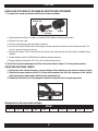
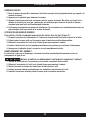
ADJUSTING FASTENER LENGTH
1. Unplug tool from electrical supply or remove battery before adjusting nose-piece for fastener length.
2. Depress the screw selector pin until it is flush with nosepiece and slide the nosepiece to the desired
setting by aligning hatch marks with the silver adjustment pin.
3. Release pin ensuring it is fully engaged in selected nosepiece slot for proper operation.
Nosepiece has these possible settings:
DS530
1" 1 1/4” 1 1/2” 1 5/8” 1 3/4” 2” 2 1/4” 2 1/2” 2 3/4” 3”

TOOL USE
LOADING THE TOOL
CAUTION
Beware of sharp points on screws. Avoid grabbing this area during loading and
operation.
11. Make sure the heads of the screws are resting on top of the plastic colla-
tion material.
This will ensure proper strip advancement and prevent jamming.
2. Check for proper fastener length setting (see “Adjusting for Fastener
Length” above).
3. Feed the strip into the strip guide up toward the nose of the tool.
4. Feed the strip into the slide body until the first screw is aligned with the bit. The tool will feed all
subsequent screws automatically as the tool is pulled back off the work surface, returning to its
relaxed state.
5. To remove the strip, pull it through from the top of the nosepiece.
ADJUSTING DEPTH OF DRIVE
1. This tool is equipped with a locking depth-control adjustment.
2. Depress the lock switch to release the thumbwheel and rotate it to a notched position. Adjust the
amount of countersink by turning the thumbwheel clockwise to go more shallow, or counter-clock-
wise to go deeper. Release the lock button after adjustment, and make sure the thumbwheel is
locked into a notched position.
3. Test drive screws while adjusting until the desired countersink is reached.
DRIVING SCREWS
1. Whenever possible, hold the tool at a right angle (perpendicular) to the work surface.
2. Pull the trigger to start the motor.
3. Press the nosepiece with constant force against the work surface. Do not remove the tool from the
work surface until the clutch disengages and the bit stops rotating, signalling a fully driven screw.
4. Continue to allow the motor to run. The next screw will be automatically fed into place when the tool
is pulled off the work surface.
9

TOOL USE
10
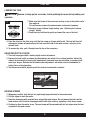
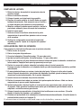
REVERSE OPERATION
To operate tool in reverse for removal of screws (refer to Figure 1):
1. Flip the forward/reverse switch on the tool to reverse rotation.
2. Rotate the clamp on the attachment to the unlock position.
3. Slide the attachment off the tool to expose the bit.
4. Insert bit into screw and apply/maintain pressure to engage clutch.
5. Pull trigger until screw is completely disengaged.
BIT REPLACEMENT
Due to wear or damage, the bit will need to be replaced periodically or when changing screw recess type.
CAUTION
Remove battery or unplug tool before attempting to replace the bit.
1. Turn the clamp on the attachment to the unlock position.
2. Slide the attachment off the tool to expose the bit.
3. Remove bit per tool manufacturer’s instructions
4. Insert the new bit per tool manufacturer’s instructions.
5. Install attachment and rotate clamp to lock position.
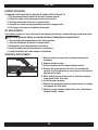
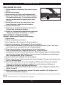
NOSEPIECE REPLACEMENT
1. Remove battery or unplug the tool before changing the
nosepiece.
2. Remove retention screw.
3. Set the nosepiece on the longest setting possible.
4. Depress the screw selector pin until it is completely de-
pressed. It will be necessary to use a screw or thin object to
depress to this depth.
5. While holding the pin in this position, slide the nosepiece
forward and off the slide body.
6. Install the new nosepiece.
7. Replace the nosepiece retention screw ensuring it is seated
snug against the slide body.
8. Check for proper fastener length setting (see “Adjusting for
Fastener Length” above).

TOOL USE
11
INSTALLING THE EXTENSION POLE
To prepare the screwgun for using the extension pole:
1. Remove the nose cone.
2. Remove bit holder assembly.
3. Attach adapter. (See page 7-8 for details.)
4. Tighten set screws. (See page 7-8 for details.)
5. Remove the extension pole drive shaft from inside the extension pole, and insert it into the tool.
Push it in until you hear it snap into place.
6. Slide the extension pole shell down onto the drive shaft.
Thread the extension pole on to the adapter until it’s all the way down and hand-tight.
7. The handle should slide over and down the pole. Place the collar over the bottom of extension pole
just above the adapter. Tighten by spinning the handle clockwise in the desired orientation. (Do not
overtighten).
8. Insert the bit into the end of the extension pole.
9. Slide the attachment down over the top of the bit. Pull it on tight, making sure there’s no gap.
10. Tighten clamp. Adjust the screw if necessary to provide more or less clamping force. This should
be tight enough to prohibit the attachment from easily rotating on the adapter or sliding off with
minimal force.
11. Set nosepiece for the length of screws to be driven. (See Adjusting Fastener Length, on page 8)
12. Set depth of drive for the desired amount of countersink. (See Adjusting Depth of Drive on page 9)
The attachment is now installed and you are ready to load in a screw strip and begin driving screws.
Load the tool and drive screws as described on page 9.

12
Maintenance
Read section titled “Safety Warnings” before maintaining tool.
1. With battery removed or cord disconnected, make daily inspection to ensure free movement of
nosepiece and trigger.
Do not use tool if nosepiece or trigger sticks or binds.
2. Lubrication of the feed system is not necessary. DO NOT OIL.
3. Wipe tool clean daily and inspect for wear, especially the bit and nosepiece. Replace as necessary.
WARNING
Repairs other than those described here should be performed only by trained,
qualified personnel. Contact SENCO for information at 1-800-543-4596.
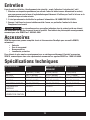
Accessories
SENCO offers a full line of DuraSpin screws and accessories for your SENCO tools, including:
• Bits
• Storage Bag
• Assorted Nosepieces
• Safety Glasses
For more information or a fully illustrated catalogue of Senco accessories, contact your sales
representative or call Senco at 1-800-543-4596.
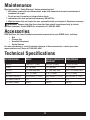
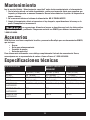
Technical Specifications
SPECIFICATION DS530 DS530-S1/DS530-D1/
DS530-M1
DS532/DS534
WEIGHT 1.65 LBS. (.75 KG) 3.5 LBS. (1.6 KG) 7 LBS. (3.2 KG)
HEIGHT 3.5" (89 MM) 3.5" (89 MM) 7" (178 MM)
LENGTH 22" (556 MM) MAX 33" (838 MM) MAX 40.5" (1029 MM) MAX
WIDTH 2.75" (70 MM) 2.75" (70 MM) 2.75" (70 MM)
FASTENER CAPACITY 50 SCREWS (1 STRIP) 50 SCREWS (1 STRIP) 50 SCREWS (1 STRIP)
FASTENER LENGTH 1-3" 1-3" 1-3"
FASTENER RANGE #6-#12 #6-#12 #6-#12

13
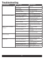
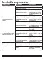
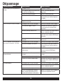
Troubleshooting
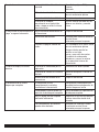
Problem/Symptom Probable Cause Corrective Action
Tool will not fully drive fastener Bit is worn Replace bit
Power capabilities of the tool have
been exceeded Discontinue use in that application
Tool is in reverse Switch tool to forward
Incorrect bit installed Ensure correct bit type and length
are installed
Depth of drive not set properly See p. 9 for proper adjustment
Tool does not advance fastener Screw length is improperly set See p. 8-9 for proper adjustment
Return spring is weak Replace or return to authorized
service center for repair
Defective collation material Use Senco branded fasteners for
optimum performance
Defective slide body Replace or return to Senco autho-
rized service center for repair
Screw strip is jammed in guide
track Ensure strip slides free in guide
track
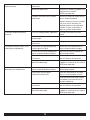
Screws “kick out” or misdrive
during use Screw length improperly set See p. 9-10 for proper
adjustment
Incorrect bit installed Ensure correct bit type and length
are installed
Defective or damaged feed system Return to Senco Authorized
service centre for repair
Bit slips off screw or screw is
driven at an angle Tool slid forward during drive Hold tool firmly while driving
Bit is worn or broken Replace bit
Nosepiece is worn or damaged Replace or return to Senco autho-
rized service centre for repair
Fastener jams Screw length improperly set See p. 9-10 for proper
adjustment
Defective collation material Use Senco branded fasteners for
optimum performance
Nosepiece damaged or bent Replace nosepiece
Screw partially driven into collation
material then feed system released Remove jammed screw with
fingers or pliers and resume use

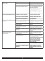
14
Slide mechanism ”sticks” or
returns slowly Debris build-up in mechanism Clean mechanism
Weak return spring Replace or return to Senco
authorized service centre for repair
Bit sticking in collation material Use Senco branded fasteners for
optimum performance
Always attempt to store screws
in cool, dry place before use.
Overheated collation can get soft
and cause a delay in feed system
return
Pushing force becomes excessive Improper screw for application Consider alternative fastener
CAM screw is loose or damaged Tighten or replace CAM screw
Debris build-up on mechanism Clean mechanism
Attachment will not fully
install/lock The attachment is not fully insert-
ed and seated onto the tool Verify that the attachment is fully
seated before attempting to lock
the collar
The clamp is not turned to the full
unlock position Rotate the clamp to full unlock
position
Foreign object stuck inside
attachment Make sure that no objects or parts
are jammed inside the connection
Components in connector may be
damaged Replace connector or return to
Senco Authorized service centre
for repair
Attachment will not fully
uninstall/unlock The clamp is not turned to the full
unlock position Rotate the clamp to full unlock
position
The attachment is catching on the
front end of the tool Avoid removing at any angle, pull
attachment straight off and away
from the tool to remove
When in full unlock position,
maneuver attachment up and
down to disengage grabbing
features from tool
Foreign object stuck inside
attachment Be sure that no objects or parts
are jammed inside the connection
Components in connector may be
damaged Replace connector or return to
Senco Authorized service centre
for repair

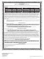
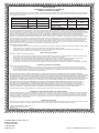
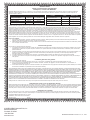
Limited Warranty
SENCO® Pneumatic, DuraSpin®, Cordless Tools
& Compressors
KYOCERA-SENCO Industrial Tools, Inc. (“SENCO”) designs and constructs its products using the highest standards of material and workmanship.
SENCO warrants to the original retail purchaser that the following products will be free from defects in material or workmanship for the warranty period
Products New Reconditioned Products New Reconditioned
Pneumatic Tools ÜFive Years One Year Air Compressors One Year 90 Days
Fusion Tools Five Years Six Months Combo Kit Tools One Year 90 Days
Gas Tools Two Years Six Months Multi-Blow Hand Nailers One Year 90 Days
Duraspin Tools Five Years 90 Days Stapling Hammers One Year 90 Days
Ü = Both XP and Pro Series
During the warranty period (which begins on the purchase date), SENCO will repair or replace, at SENCO’s option and expense, any product or part
that is defective in materials or workmanship after examination by a SENCO Authorized Warranty Service Centre, subject to the exceptions, exclusions
and limitations described below. Any replacement product or part will carry a warranty for the balance of the warranty period applicable to the replaced
product or part. A DATED SALES RECEIPT OR PROOF OF PURCHASE FROM THE ORIGINAL RETAIL PURCHASER IS REQUIRED TO MAKE A
WARRANTY CLAIM. Warranty registration is also required and can be accomplished through on-line Product Registration at www.senco.com or by
completing and returning the postage paid warranty registration form included with your Operator’s manual/parts chart information, found inside the
product carton. To make a warranty claim, you must return the product, with proper receipt/proof of purchase and return transportation charges prepaid,
to a SENCO Authorized Warranty Service Centre. A list of SENCO Authorized Warranty Service Centres can be found at www.senco.com or by calling
1-800-543-4596 toll free. SENCO will perform its obligations under this warranty within a reasonable time after approval of the warranty claim.
SENCO Cordless:
1. Subject to the exceptions, exclusions and limitations described below, SENCO warrants that the SENCO Cordless tool will be free from defects
in materials and workmanship for two years after the purchase date.
2. SENCO warrants that the batteries and chargers used with SENCO Cordless tools will be free from defects in material and workmanship for
one year after the purchase date.
Warranty Exclusions
The following warranty exclusions apply:
1.
seals, driver blades, piston stops, and piston/driver assembly.
2. This warranty does not cover parts damaged due to normal wear, misapplication, misuse, accidents, operation beyond the recommended
speeds or voltage (electric units only), improper storage, or damage resulting from shipping.
3. Prod
4. Labour charges or loss or damage resulting from improper operation, maintenance or repairs are not covered by this warranty.
General Warranty Conditions
This warranty will be honoured only if:
A. Clean, dry, regulated compressed air has been used, at air pressure not exceeding the maximum indicated on the tool casting;
B. No e
C. No d
maintenance instructions).
THIS WARRANTY IS THE ONLY WARRANTY ON THE PRODUCT, AND SENCO DISCLAIMS ALL OTHER WARRANTIES. ANY IMPLIED WAR-
RANTIES WILL BE LIMITED IN DURATION TO THE APPLICABLE WARRANTY PERIOD SPECIFIED ABOVE. SOME STATES DO NOT ALLOW
LIMITATIONS ON HOW LONG AN IMPLIED WARRANTY LASTS, SO THE ABOVE LIMITATION MAY NOT APPLY TO YOU. YOUR REMEDIES ARE
SOLELY AND EXCLUSIVELY AS STATED ABOVE. SENCO SHALL IN NO EVENT BE LIABLE FOR INCIDENTAL, CONSEQUENTIAL, INDIRECT,
OR SPECIAL DAMAGES. SOME STATES DO NOT ALLOW THE EXCLUSION OR LIMITATION OF INCIDENTAL OR CONSEQUENTIAL DAMAGES,
SO THE ABOVE LIMITATION OR EXCLUSION MAY NOT APPLY TO YOU. IN NO EVENT, WHETHER AS A RESULT OF A BREACH OF CONTRACT,
WARRANTY, TORT (INCLUDING NEGLIGENCE) OR OTHERWISE, SHALL SENCO’S LIABILITY EXCEED THE PRICE OF THE PRODUCT WHICH
HAS GIVEN RISE TO THE CLAIM OR LIABILITY. ANY LIABILITY CONNECTED WITH THE USE OF THIS PRODUCT SHALL TERMINATE UPON THE
EXPIRATION OF THE WARRANTY PERIOD SPECIFIED ABOVE. NO EMPLOYEE OR REPRESENTATIVE OF SENCO OR ANY DISTRIBUTOR OR
DEALER IS AUTHORIZED TO MAKE ANY CHANGE OR MODIFICATION TO THIS WARRANTY.
Replacement of Tool Due to Natural Disaster
Such a claim will be honoured provided that the original retail purchaser had previously submitted a completed warranty registration card for the tool,
and then submits proof of ownership and an acceptable statement describing such Act of God documented by an insurance carrier, police department,
Customer Satisfaction
If for any reason the product does not perform to the original purchaser’s satisfaction, it can be returned to the place of purchase within thirty days with
dated sales receipt for a full refund of the purchase price (applies to new product sales only).
© 2022 KYOCERA-SENCO Industrial Tools, Inc.
CINCINNATI, OHIO 45244-1611 USA
www.senco.com
160101
KYOCERA-SENCO Industrial Tools, Inc.
8450 Broadwell Road
Cincinnati, OH 45244
1-800-543-4596
www.senco.com © 2022 by KYOCERA-SENCO Industrial Tools, Inc.

KYOCERA-SENCO Industrial Tools, Inc.
8450 Broadwell Road
Cincinnati, OH 45244
1-800-543-4596
www.senco.com © 2022 by KYOCERA-SENCO Industrial Tools, Inc.

KYOCERA-SENCO Industrial Tools, Inc.
8450 Broadwell Road
Cincinnati, OH 45244
1-800-543-4596
www.senco.com © 2022 por KYOCERA-SENCO Industrial Tools, Inc.
NFD810X • Emitido el 18 de mayo de 2022 (Reemplaza 6/13/2021)
Serie DS530
ADITAMENTO DEL SISTEMA DE
ALIMENTACIÓN AUTOMÁTICA
DE TORNILLOS
Instrucciones de operación
IMPORTANTE:
Lea este documento
antes de utilizar la
herramienta.

Índice
Advertencias generales de seguridad al usar herramientas eléctricas ..................................................4
Seguridad en el área de trabajo .............................................................................................................. 4
Seguridad con la electricidad .................................................................................................................4
Seguridad personal ................................................................................................................................4
Uso y cuidado de las herramientas eléctricas ........................................................................................5
Servicio ..................................................................................................................................................5
Descripción funcional ...............................................................................................................................6
Operación de la herramienta .................................................................................................................... 7
Instalación del aditamento DS530 ..........................................................................................................7
Ajuste de la longitud del sujetador .........................................................................................................8
Carga de la herramienta .........................................................................................................................9
Ajuste de la profundidad a la que se introducen los tornillos .................................................................9
Inserción de los tornillos ........................................................................................................................9
Operación inversa ................................................................................................................................10
Reemplazo de la broca ......................................................................................................................... 10
Reemplazo de la punta ......................................................................................................................... 11
Instalación del poste de extensión .......................................................................................................11
Mantenimiento ........................................................................................................................................ 12
Accesorios ............................................................................................................................................... 12
Especificaciones técnicas ....................................................................................................................... 12
Solución de problemas ...........................................................................................................................13
2

3
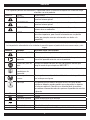
SÍMBOLOS
Las siguientes palabras de señalización y significados tienen la intención de explicar los niveles de riesgo
asociados con este producto.
SÍMBOLO SEÑAL SIGNIFICADO
PELIGRO: Indica una situación peligrosa que, si no se evita, provocará la
muerte o lesiones graves.
ADVERTENCIA: Indica una situación peligrosa que, si no se evita, puede provocar la
muerte o lesiones graves.
PRECAUCIÓN: Indica una situación peligrosa que, si no se evita, puede provocar
lesiones leves o moderadas.
AVISO: (Sin símbolo de alerta de seguridad) indica información que se
considera importante, pero no está relacionada con una posible
lesión (por ejemplo, mensajes relacionados con daños a la
propiedad).
Se pueden usar algunos de los siguientes símbolos en este producto. Estúdielos y aprenda su significado.
La interpretación adecuada de estos símbolos le permitirá operar el producto de una manera mejor y más
segura.
SÍMBOLO NOMBRE DESIGNACIÓN O EXPLICACIÓN
Alerta de seguridad Indica un posible riesgo de lesiones personales.
Lea el manual del
operador
Para reducir el riesgo de lesiones, el usuario debe leer y entender el
manual del operador antes de usar este producto.
Protección para los
ojos
Siempre use protección para los ojos con guardas laterales que
tenga la marca de que cumple con ANSI Z87.1.
Alerta de
condiciones de
humedad
No exponga la herramienta a la lluvia ni la use en lugares húmedos.
No acerque las
manos
Mantenga las manos lejos de la cuchilla, de lo contrario, podría sufrir
una lesión personal grave.
Reciclaje Este producto utiliza baterías de iones de litio. Las leyes locales,
estatales o federales pueden prohibir que se desechen las baterías
en la basura ordinaria. Consulte a su autoridad local de residuos
para obtener información sobre las opciones disponibles de reciclaje
y desecho.
VVoltios Voltaje
min Minutos Tiempo
Corriente continua Tipo o característica de la corriente
Corriente alterna Tipo o característica de la corriente
no Velocidad sin carga Velocidad de rotación, sin carga
.../min Por minuto Revoluciones, golpes, velocidad superficial, órbitas, etc. por minuto

Advertencias generales de seguridad
al usar herramientas eléctricas
Lea todas las advertencias de seguridad, instrucciones, ilustraciones y
especificaciones que se le proporcionan con esta herramienta eléctrica. El incumplimiento de todas las
instrucciones enumeradas a continuación puede provocar descargas eléctricas, incendios o lesiones graves.
Guarde todas las advertencias e instrucciones para una consulta posterior.
El término “herramienta eléctrica” en las advertencias se refiere a una herramienta eléctrica que funciona
con la red eléctrica (con cable) o a una que funciona con una batería (inalámbrica).
SEGURIDAD EN EL ÁREA DE TRABAJO
1. Mantenga su área de trabajo limpia y bien iluminada. Las áreas desordenadas u oscuras promueven accidentes.
2. No opere herramientas eléctricas en atmósferas explosivas, por ejemplo, en presencia de polvo, gases o líquidos
inflamables. Las herramientas eléctricas crean chispas que pueden encender el polvo o los vapores.
3. Mantenga alejados a los niños y las personas que estén en los alrededores mientras opera una herramienta
eléctrica. Las distracciones pueden hacer que pierda el control.
4. El aditamento de destornillador de alimentación automática incluido fue diseñado para funcionar con una marca y
varios modelos de destornilladores eléctricos. Consulte el manual del operador del fabricante del destornillador para
obtener instrucciones de seguridad y operación relacionadas.
SEGURIDAD CON LA ELECTRICIDAD
5. Los enchufes de las herramientas eléctricas deben coincidir con el tomacorriente. No haga ningún tipo de
modificación al enchufe. No utilice la herramienta eléctrica conectada a tierra con un enchufe adaptador. Los
enchufes no modificados y los tomacorrientes correspondientes reducirán el riesgo de una descarga eléctrica.
6. Evite el contacto del cuerpo con las superficies conectadas a tierra, como tuberías, radiadores, estufas y
refrigeradores. Existe un mayor riesgo de descarga eléctrica si su cuerpo está conectado a tierra.
7. No exponga las herramientas eléctricas a la lluvia o a condiciones de humedad. Si le entra agua a una herramienta
eléctrica aumentará el riesgo de una descarga eléctrica.
8. No maltrate el cable. Nunca use el cable para transportar, jalar o desenchufar la herramienta eléctrica. Mantenga
el cable alejado del calor, aceite, bordes afilados o piezas móviles. Si el cable está enredado o dañado, aumenta el
riesgo de una descarga eléctrica.
9. Cuando opere una herramienta eléctrica en exteriores, use un cable de extensión adecuado para uso en exteriores.
Si es inevitable utilizar una herramienta eléctrica en una ubicación húmeda, utilice un suministro protegido por un
DISPOSITIVO DE CORRIENTE RESIDUAL (RCD). El uso de un cable adecuado para uso en exteriores reduce el riesgo
de una descarga eléctrica.
10. Sujete la herramienta eléctrica utilizando las superficies de agarre aisladas cuando realice una operación en la que
el sujetador pueda entrar en contacto con cables ocultos. Los sujetadores que entran en contacto con un cable que
lleva energía pueden hacer que las partes metálicas expuestas de la herramienta eléctrica “se energicen” y podrían dar al
operador una descarga eléctrica.
11. Si es inevitable utilizar una herramienta eléctrica en una ubicación húmeda, utilice un suministro protegido por un
dispositivo de corriente residual (RCD). El uso de un RCD reduce el riesgo de una descarga eléctrica.
SEGURIDAD PERSONAL
12. Manténgase alerta, observe lo que está haciendo y use el sentido común al operar una herramienta eléctrica. No
use una herramienta eléctrica cuando esté cansado o bajo los efectos de drogas, alcohol o medicamentos. Un
momento de falta de atención al operar una herramienta eléctrica puede causar lesiones personales graves.
13. Use equipo de protección personal. Siempre use protección para los ojos. El equipo de protección como una
mascarilla antipolvo, zapatos de seguridad antideslizantes, casco o protección auditiva para condiciones apropiadas
reducirá las lesiones personales.
4
La page charge ...
La page charge ...
La page charge ...
La page charge ...
La page charge ...
La page charge ...
La page charge ...
La page charge ...
La page charge ...
La page charge ...
La page charge ...
La page charge ...
La page charge ...
La page charge ...
La page charge ...
La page charge ...
La page charge ...
La page charge ...
La page charge ...
La page charge ...
La page charge ...
La page charge ...
La page charge ...
La page charge ...
La page charge ...
La page charge ...
La page charge ...
La page charge ...
-
 1
1
-
 2
2
-
 3
3
-
 4
4
-
 5
5
-
 6
6
-
 7
7
-
 8
8
-
 9
9
-
 10
10
-
 11
11
-
 12
12
-
 13
13
-
 14
14
-
 15
15
-
 16
16
-
 17
17
-
 18
18
-
 19
19
-
 20
20
-
 21
21
-
 22
22
-
 23
23
-
 24
24
-
 25
25
-
 26
26
-
 27
27
-
 28
28
-
 29
29
-
 30
30
-
 31
31
-
 32
32
-
 33
33
-
 34
34
-
 35
35
-
 36
36
-
 37
37
-
 38
38
-
 39
39
-
 40
40
-
 41
41
-
 42
42
-
 43
43
-
 44
44
-
 45
45
-
 46
46
-
 47
47
-
 48
48


Senco DS530 Series Manuel utilisateur
- Catégorie
- Outils électroportatifs
- Taper
- Manuel utilisateur
dans d''autres langues
- English: Senco DS530 Series User manual
- español: Senco DS530 Series Manual de usuario