SCOPREGA Turbo Max 12v For Inflatables Electric Inflator Manuel utilisateur
- Taper
- Manuel utilisateur

1
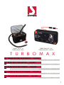
TURBOMAX
TURBO MAX 12V
TURBO MAX 24V/S
TURBO MAX KIT 12V
TURBO MAX KIT 24V/EV
CONSERVARE QUESTE ISTRUZIONI
GONFIATORE ELETTRICO - 12/24VIT
SAVE THIS INSTRUCTIONS MANUAL FOR REFERENCE
ELECTRIC INFLATOR – 12/24VEN
DIESE ANLEITUNG AUFBEWAHREN
ELEKTRISCHE PUMPE – 12/24VDE
CONSERVER CES INSTRUCTIONS
GONFLEUR ELECTRIQUE – 12/24VFR
GARDER ESTAS INSTRUCCCIONES
INFLADOR ELECTRICO – 12/24VES

2
INDICE
1. DESCRIZIONE FUNZIONALE
2. PREMESSA
3. AVVERTENZE PRELIMINARI
4. INTRODUZIONE
5. UTILIZZI CONSIGLIATI
6. DATI TECNICI
7. REGOLE DI SICUREZZA GENERALI
8. UTILIZZO E FUNZIONAMENTO
9. MONITORAGGIO STATO GONFIATORE E BATTERIA
10. SOLUZIONE DEI PROBLEMI
8.1 ACCESSORI E CAVI DI ALIMENTAZIONE
8.2 COLLEGAMENTO E ACCESSORI
8.3 ACCESSORI DEL GONFIATORE
8.4 AVVERTENZA SUGLI ACCESSORI
10.1 SOLO PER TURBOMAX KIT 12V e TURBOMAX KIT 24V-EV

3
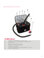
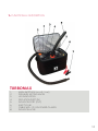
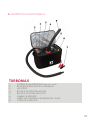
TURBOMAX
1. INTERRUTTORI PRINCIPALI (on-o / start)
2. MANOPOLA DI REGOLAZIONE DELLA PRESSIONE
3. LED DI STATO
4. BOCCA DI SGONFIAGGIO (IN)
5. BOCCA DI GONFIAGGIO (OUT)
6. FUSIBILE DI SICUREZZA
7. CAVO CON MORSETTI DI ALIMENTAZIONE A 12/24 V
8. TUBO DI GONFIAGGIO
1. DESCRIZIONE FUNZIONALE

4
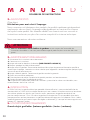
MANUALEDI
CONSERVARE QUESTE ISTRUZIONI
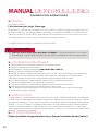
2. PREMESSA
Gentile cliente,
congratulazioni per aver scelto Scoprega.
Progettiamo e fabbrichiamo prodotti della massima qualità secondo le
esigenze della nostra clientela. Scoprega o re la massima qualità anche
nell’assistenza. I nostri u ci dedicati garantiscono consulenza e istruzioni in
caso di bisogno, oltre a un’assistenza tecnica completa.
La ringraziamo per la fi ducia.
4. INTRODUZIONE
Il TURBO MAX è un gonfi atore elettrico portatile ad alta e cienza, sinonimo di a dabilità e
funzionalità. Il TURBO MAX è dotato di due potenti motori in corrente continua che azionano turbine
poste in serie fra di loro, che permettono di gonfi are qualsiasi oggetto a una pressione compresa
tra i 175 ed i 250 mbar. Il gonfi atore è dotato di LED che monitorano lo stato della pompa durante
il funzionamento. Il gonfi atore si avvia quando si preme il tasto ON e si spegne automaticamente
quando raggiunge la pressione impostata sulla manopola (2). Quando l’utilizzatore preme il tasto
OFF, l’apparato si arresta.
5. UTILIZZI CONSIGLIATI
Oggetti gonfi abili di grandi dimensioni (gommoni / tende / zattere).
Leggere queste istruzioni prima di utilizzare il gonfi atore. La mancata osservanza di
tutte le istruzioni elencate di seguito può provocare danni al prodotto e/o causare lesioni
gravi alle persone.
ATTENZIONE
1. Attenersi a tutte le istruzioni presenti su questo documento.
2. Conservare le presenti istruzioni.
3. Non ostruire le bocchette di aerazione (VEDI FIGURA A PAG. 3).
4. Proteggere sempre il cavo di alimentazione.
5. Non aprire il gonfi atore. Far eseguire tutte le attività di manutenzione a manutentori qualifi cati
autorizzati da Scoprega. La manutenzione è necessaria quando l’apparecchio risulta in qualche
modo danneggiato o non funzionante.
6. Non manomettere il prodotto. L’apertura del gonfi atore comporta la decadenza della garanzia.
7. Fornire una ventilazione adeguata
8. Evitare di posizionare oggetti nelle vicinanze del prodotto durante il suo funzionamento.
9. Tenere il presente prodotto fuori dalla portata dei bambini.
10. Il gonfi atore in moto produce vibrazioni per cui, per evitare cadute accidentali, ne consigliamo
l’utilizzo a pavimento.
3. AVVERTENZE PRELIMINARI

5
ISTRUZIONI
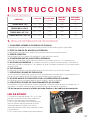
7. REGOLE DI SICUREZZA GENERALI
1. CONSIDERARE SEMPRE L’AMBIENTE DI LAVORO.
Non esporre il gonfi atore alla pioggia. Non utilizzare in presenza di liquidi o gas infi ammabili.
2. EVITARE L’AVVIO ACCIDENTALE.
Non avviare il gonfi atore con la bocca di ingresso in contatto con polvere o acqua.
3. PRESTARE ATTENZIONE.
Prestare attenzione a quello che si sta facendo. Usare il buon senso.
4. CONTROLLARE CHE NON VI SIANO PARTI DANNEGGIATE.
Prima di usare il gonfi atore, ispezionare con attenzione le pareti esterne e i suoi componenti.
5. NON AVVIARE i gonfi atori portatili nei pressi di liquidi infi ammabili o atmosfere gassose o
esplosive. I motori di questi gonfi atori producono scintille che possono rilasciare fumi.
6. ATTENZIONE A NON INALARE!
L’aria compressa proveniente dal gonfi atore non è pura. Non inalare mai aria dal gonfi atore.
7. ATTENZIONE! PERICOLO DI SCOPPIO.
Gonfi are l’unità gonfi abile solo seguendo le raccomandazioni del costruttore. Una pressione
eccessiva può causare l’esplosione del gonfi abile, che può cagionare lesioni personali.
8. NON LASCIARE MAI IL DISPOSITIVO SENZA SORVEGLIANZA.
Il gonfi aggio eccessivo può causare gravi lesioni e danni materiali.
9. ATTENZIONE! PERICOLO DI FUNZIONAMENTO NON SICURO
Non modifi care o tentare di riparare l’unità. Non forare o apportare modifi che al gonfi atore o ai suoi
accessori. Qualunque modifi ca al prodotto comporta la decadenza della garanzia.
10. Non trasportare mai il gonfi atore dal tubo fl essibile né dal cavo di
alimentazione.
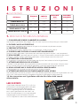
6. DATI TECNICI
ARTICOLO TENSIONE
(V)
PORTATA
(L/minuto)
TURBO MAX 12V 9.5 ÷ 14.5
PRESSIONE
MAX
(mbar)
250
1000
CONSUMO
CORRENTE
(A)
70
TURBO MAX 24V/S
TURBO MAX KIT 24V-EV
19.5 ÷ 28.5
19.5 ÷ 28.5
250
250
1000
1000
35
35
TURBO MAX KIT 12V 9.5 ÷ 14.5 250
1000 70
LED DI STATO
Il gonfi atore è dotato di due LED (A e B) che
permettono il monitoraggio dello stato della
batteria e la temperatura della pompa.
Il LED A segnala gli errori di funzionamento
per il quale il gonfi atore ha arrestato il suo
ciclo di funzionamento (si rinvia al paragrafo
Monitoraggio Stato Gonfi atore e Batteria).
Il LED B segnala lo stato di carica della batteria

6
8. UTILIZZO E FUNZIONAMENTO
1. Nelle versioni TURBO MAX 12V e TURBO MAX 24V/S, il tubo di gonfi aggio, gli
adattatori ed il cavo con morsetti sono inseriti nella borsa.
2. Nelle versioni TURBO MAX KIT12V e TURBO MAX KIT 24V-EV, essendo destinate ad
un’installazione fi ssa, sono fornite le sta e e le viti di montaggio, il cavo di alimentazione
è lungo 50 cm ed è cablato con un connettore da 100 A.
Il tubo di gonfi aggio e raccordi per valvole vengono forniti solo su richiesta.
Adattatori per valvole a baionetta sono disponibili come optional (consultare catalogo).
8.1 ACCESSORI E CAVI DI ALIMENTAZIONE
1. Scegliere l’adattatore più idoneo per la valvola presente sull’oggetto da gonfi are.
Un apposito adattatore deve inserirsi nella valvola e mantenerla aperta durante tutta la
fase di gonfi aggio/sgonfi aggio.
2. Assicurarsi che l’interruttore principale sia su OFF.
3. Collegare il tubo di gonfi aggio in base all’operazione da e ettuare:
per gonfi are (collegare all’uscita OUT), per sgonfi are (collegare all’uscita IN).
4. Inserire l’adattatore nella valvola dell’oggetto da gonfi are/sgonfi are.
8.2 COLLEGAMENTO DEGLI ACCESSORI
1. Collegare i morsetti alla batteria o assicurarsi per le versioni KIT che i connettori di
alimentazione siano collegati correttamente
2. Stendere sempre il cavo elettrico.
3. Selezionare la pressione di gonfi aggio desiderata (valore tra 175 e 250 mbar).
4. Mettere l’interruttore su ON. Il LED B inizia a lampeggiare segnalando lo stato della
batteria (si rinvia al paragrafo Monitoraggio Stato Gonfi atore e Batteria)
5. Premere l’interruttore START. Il LED B passa da lampeggiante a fi sso con il colore dello
stato batteria
6. In fase di gonfi aggio il gonfi atore si arresterà alla pressione impostata e il LED B
tornerà a lampeggiare
7. In caso di errore il gonfi atore va in autoprotezione arrestandosi. Il LED A si illumina
per indicare il tipo di problema (si rimanda al paragrafo Monitoraggio Stato Gonfi abile
e Batteria). Dopo aver risolto il problema è necessario premere START per riavviare il
gonfi atore.
8. Per sgonfi are, collegare il tubo all’uscita IN e porre la manopola di regolazione della
pressione su 175 mbar.
8.3 ACCENSIONE DEL GONFIATORE
Nel caso si utilizzino le pinze a coccodrillo, assicurarsi della corretta polarità (morsetto
rosso collegato al positivo della batteria).
In caso contrario il gonfi atore non si avvierà.
ATTENZIONE

7
Prestare attenzione quando si collega il cavo di alimentazione alla batteria per evitare
che si generino corto circuiti con conseguente pericolo di incendio
ATTENZIONE
Non lasciare mai incustodito il gonfi atore acceso. Il gonfi aggio eccessivo di un oggetto
può provocare gravi conseguenze.
ATTENZIONE
Controllare la tensione. Non collegare il gonfi ature a 12V con una batteria a 24V.
ATTENZIONE
Controllare sempre la pressione massima di gonfi aggio per evitare rischi di scoppio.
ATTENZIONE
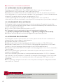
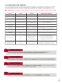
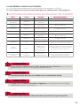
9. MONITORAGGIO STATO GONFIATORE E BATTERIA
LED BLED A STATO POSSIBILE SOLUZIONE
OFF
Stand By
Batteria CARICA
Stand By
Batteria BASSA
Stand By
Batteria SCARICA
In funzione
Batteria BASSA
In funzione
Batteria SCARICA
FINE CICLO per
Batteria SCARICA
FINE CICLO per
SOTTOTENSIONE o
SOVRATENSIONE
Tensione inferiore ai
limiti consentiti
FINE CICLO per
SOVRATEMPERATURA
In funzione
Batteria CARICA
Ricaricare la batteria
Si consiglia di ricaricare la batteria
prima di procedere.
Ricaricare la batteria
Ricaricare la batteria e poi premere
START per far ripartire il gonfi atore
Verifi care che la tensione della batteria
sia compresa nei valori descritti nel
paragrafo DATI TECNICI
Aspettare che i LED smettano di
lampeggiare e premere START per far
ripartire il gonfi atore
Si consiglia di ricaricare la batteria
prima di procedere.
SPENTO
VERDE
lampeggiante
GIALLO
lampeggiante
ROSSO
lampeggiante
GIALLO
fi sso
ROSSO
fi sso
ROSSO
lampeggiante
VERDE
lampeggiante
Lampeggiante
(colore dipende da
stato batteria)
VERDE
fi sso
ROSSO
lampeggiante
SPENTO
SPENTO
SPENTO
SPENTO
SPENTO
SPENTO
ROSSO
ROSSO
SPENTO
Gli accessori raccomandati nell’utilizzo del gonfi atore sono quelli originali SCOPREGA.
L’uso di qualsiasi accessorio non raccomandato per questo gonfi atore può essere pericoloso.
8.4 AVVERTENZA SUGLI ACCESSORI

8
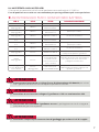
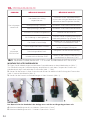
PROBLEMA POSSIBILE CAUSA POSSIBILE SOLUZIONE
Il gonfi atore
non parte
Il gonfi atore
non gonfi a
Cavo di alimentazione non
collegato correttamente.
Sottotensionedi tensione nella batteria.
Sovratensione tensione nella batteria.
Errato collegamento del tubo.
Non è stato premuto il tasto ON.
Il fusibile di protezione è bruciato.
Errata impostazione della pressione.
Interruttore non in posizione START.
L’apparato è danneggiato
Collegare il cavo di alimentazione
correttamente e con la giusta
polarità morsetto rosso al positivo
della batteria).
Controllare lo stato della batteria.
Controllare lo stato della batteria.
Collegare il tubo dell’aria alla
bocca corretta.
Premere il tasto ON.
Sostituire il fusibile con uno dello
stesso tipo (40 o 70 A).
Correggere l’impostazione della
pressione.
Posizionare interruttori principali su
ON e poi premere START.
Rivolgersi a un centro di
assistenza SCOPREGA.
10. SOLUZIONE DEI PROBLEMI
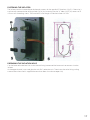
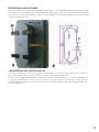
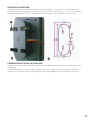
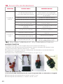
10.1 SOLO PER TURBOMAX KIT 12V e TURBOMAX KIT 24V-EV
1. Inserire sulle estremità del cavo i coperchi ed i gommini rossi (fi g. 1).
Per garantire il passaggio di corrente consigliamo, dopo la crimpatura del faston, di stagnare
l’estremità del cavo al connettore (fi g. 1 – freccia).
2. Inserire i faston nella loro sede, facendo attenzione al senso del dente di aggancio (fi g. 2) ed alla
polarità (fi g. 4).
3. Inserire nella loro sede i gommini ed i coperchi (fi g. 3).
MONTAGGIO CONNETTORE
CAVO DI ALIMENTAZIONE
La sezione del cavo di alimentazione dell’impianto di bordo deve essere adeguata alla sua
lunghezza:
4. Per lunghezza del cavo fi no a 6 metri: sezione 10 mm2
5. Per lunghezza del cavo da 6 a 12 metri: sezione 16 mm2

9
FISSAGGIO GONFIATORE
PREPARAZIONE TUBO DI GONFIAGGIO
Il gonfi atore può essere fi ssato all’imbarcazione utilizzando le squadrette “B” (fi g. 5) in dotazione,
oppure dopo aver e ettuato un foro per l’incasso a pannello (fi g. 6), si può fi ssare ai fori “A” (fi g. 5)
con delle viti autofi lettanti con Ø 4.5 mm. La lunghezza massima della vite nel gonfi atore è di 8 mm.
Tagliare il tubo della misura desiderata. Inserire in una delle due estremità il raccordo rosso per
collegare il tubo al gonfi atore.
Nell’estremità opposta inserire ed incollare il riduttore in PVC morbido. Successivamente innestare
il raccordo per la valvola facendo attenzione a scegliere dal kit in dotazione quello che consente
l’apertura completa della valvola stessa.

1
0
INDEX
1. FUNCTIONAL DESCRIPTION
2. FOREWORD
3. PRELIMINARY WARNINGS
4. INTRODUCTION
5. RECOMMENDED USES
6. TECHNICAL SPECIFICATIONS
7. GENERAL SAFETY RULES
8. USE AND OPERATION
9. INFLATOR AND BATTERY STATUS MONITORING
10. TROUBLESHOOTING
8.1 ACCESSORIES AND POWER CABLES
8.2 CONNECTION AND ACCESSORIES
8.3 INFLATOR ACCESSORIES
8.4 ACCESSORY WARNING
10.1 ONLY FOR TURBOMAX KIT 12V and TURBOMAX KIT 24V-EV

1
1
TURBOMAX
1. MAIN SWITCHES (on-o / start)
2. PRESSURE SETTING KNOB
3. LED INDICATORS
4. DEFLATION PORT (IN)
5. INFLATION PORT (OUT)
6. SAFETY FUSE
7. CABLE WITH 12/ 24V POWER CLAMPS
8. INFLATION HOSE
1. FUNCTIONAL DESCRIPTION

1
2
MANUALOF
SAVE THIS INSTRUCTIONS MANUAL FOR REFERENCE
2. FOREWORD
Dear customer,
congratulations on choosing Scoprega.
We design and manufacture products of the highest quality to meet the needs
of our customers. Scoprega o ers the highest quality in service as well. Our
specialised departments provide support and instructions when needed, as well
as comprehensive technical service.
We thank you for your trust.
4. INTRODUCTION
The TURBO MAX is a high-e ciency portable electric infl ator, which stands for reliability and
functionality. The TURBO MAX is equipped with two powerful DC motors that drive two turbines
connected in series, thus allowing any object to be infl ated to a pressure between 175 and 250 mbar.
The infl ator is equipped with LED indicators checking pump status during operation. The infl ator starts
when the ON button is pressed and automatically stops when the set pressure on the knob (2) is
reached. The device stops when the user presses the OFF button.
5. RECOMMENDED USES
Large infl atable objects (rubber dinghies / tents / rafts).
Read these instructions before using the infl ator. Failure to follow all the instructions listed
below may result in damage to the product and/or cause serious injury to persons.
WARNING
1. Comply with all instructions in this document.
2. Keep these instructions.
3. Do not block the air vents (SEE FIGURE ON PAGE 3).
4. Always protect the power cable.
5. Do not open the infl ator. Refer all servicing to qualifi ed service personnel authorised by Scoprega.
Servicing is required when the device is damaged or not working in any way.
6. Do not tamper with the product. Opening the infl ator will void its warranty.
7. Provide suitable ventilation
8. Avoid placing objects near the product during operation.
9. Keep this product out of the reach of children.
10. The operating infl ator produces vibrations: therefore, we recommend you to use it on the fl oor, so
as to avoid accidental falls.
3. PRELIMINARY WARNINGS

1
3
INSTRUCTIONS
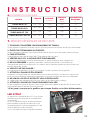
7. GENERAL SAFETY RULES
1. ALWAYS TAKE INTO ACCOUNT THE WORKING ENVIRONMENT.
Do not expose the infl ator to rain. Do not use in the presence of fl ammable liquids or gases.
2. AVOID UNINTENTIONAL STARTING.
Do not start the infl ator with the inlet in contact with dust or water.
3. PAY ATTENTION.
Pay attention to what you are doing. Use common sense.
4. CHECK THAT THERE ARE NO DAMAGED PARTS.
Before using the infl ator, carefully check its outer sides and components.
5. DO NOT OPERATE portable infl ators near fl ammable liquids or in gaseous or explosive
atmospheres. The infl ator motors produce sparks that can release fumes.
6. DO NOT INHALE!
The compressed air coming from the infl ator is not clean. Never inhale air from your infl ator.
7. WARNING! RISK OF EXPLOSION.
Infl ate the unit only complying with the manufacturer’s recommendations. Exceeding the pressure
rating could cause the infl ator to explode, resulting in personal injury.
8. NEVER LEAVE THE DEVICE UNATTENDED.
Overinfl ation could result in serious injury and property damage.
9. WARNING! RISK OF UNSAFE OPERATION
Do not modify or attempt to repair the unit. Do not drill into or make any modifi cations to the infl ator
or its accessories. Any modifi cation to the product will void its warranty.
10. Never carry the infl ator by the fl exible hose or power cable.
6. TECHNICAL SPECIFICATIONS
ITEM VOLTAGE
(V)
FLOW RATE
(L / minute)
TURBO MAX 12V 9.5 ÷ 14.5
MAX.
PRESSURE
(mbar)
250
1000
POWER
CONSUMPTION
(A)
70
TURBO MAX 24V/S
TURBO MAX KIT 24V-EV
19.5 ÷ 28.5
19.5 ÷ 28.5
250
250
1000
1000
35
35
TURBO MAX KIT 12V 9.5 ÷ 14.5 250
1000 70
LED INDICATORS
The infl ator is equipped with two LED indicators
(A and B) that allow the battery status and the
pump temperature to be checked.
LED A indicates the operating errors that
have stopped infl ator operating cycle (refer
to paragraph Infl ator and Battery Status
Monitoring).
LED B indicates battery charging status

1
4
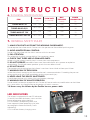
8. USE AND OPERATION
1. TURBO MAX 12V and TURBO MAX 24V/S versions: the infl ation hose, adapters and
cable with clamps are located inside the carry bag.
2. TURBO MAX KIT 12V and TURBO MAX KIT 24V-EV versions: as they are intended for a
permanent installation, brackets and retaining screws are provided. The power cable is 50 cm
long and is wired with a 100 A connector.
The infl ation hose and valve fi ttings are supplied only upon request.
Adapters for bayonet valves are available as an optional feature (see catalogue).
8.1 ACCESSORIES AND POWER CABLES
1. Choose the most suitable adapter for the valve on the object to be infl ated.
During infl ation/defl ation, the valve should be kept open by a suitable adapter.
2. Make sure that the main switch is set to OFF.
3. Connect the infl ation hose according to the operation to be performed:
to infl ate (connect to the OUT outlet), to defl ate (connect to the IN outlet).
4. Insert the adapter into the valve of the object to be infl ated/defl ated.
8.2 CONNECTING THE ACCESSORIES
1. Connect clamps to battery or, for KIT versions, make sure that the power connectors are
properly assembled
2. Always stretch the electric cable.
3. Set the desired infl ation pressure (value between 175 and 250 mbar).
4. Set the switch to ON. LED B starts fl ashing, indicating battery status (refer to paragraph
Infl ator and Battery Status Monitoring)
5. Press the START switch. LED B shifts from fl ashing to steady, the colour depends on the
battery status
6. When infl ating, the infl ator will stop at the set pressure and LED B will resume fl ashing
7. In the event of an error, the infl ator stops as a protective measure. LED A lights up to
indicate the type of problem (refer to paragraph Infl ator and Battery Status Monitoring).
Once the problem has been fi xed, the infl ator should be restarted by pressing START.
8. To defl ate, connect the hose to the IN outlet and set the pressure setting knob to 175 mbar.
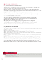
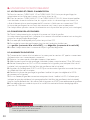
8.3 TURNING ON THE INFLATOR
In case crocodile clips are used, make sure of the correct polarity (red clamp connected to
battery positive terminal).
Otherwise the infl ator will not start.
WARNING

15
When connecting the power cable to the battery , make sure to avoid short circuits and
possible fi re risk
WARNING
Do not leave the infl ator running unattended. Overinfl ating an object could result in
serious injury.
WARNING
Check the voltage. Do not connect the 12V infl ator to a 24V battery.
WARNING
Always check the maximum infl ation pressure to avoid risks of explosion.
WARNING
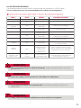
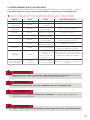
LED BLED A STATUS POSSIBLE SOLUTION
OFF
Standby, CHARGED
battery
Standby
LOW battery
Standby
LOW battery
Operating
LOW battery
Operating
LOW battery
CYCLE END due to
LOW battery
CYCLE END due to
UNDERVOLTAGE or
OVERVOLTAGE
Voltage below
permitted limits
CYCLE END due to
OVERTEMPERATURE
Operating
CHARGED battery
Charge the battery
We recommend you to charge the
battery before operating.
Charge the battery
Charge the battery and then press START
to restart the infl ator
Make sure that the battery voltage
complies with the values indicated in
paragraph TECHNICAL FEATURES
Only after the LED indicators have
stopped fl ashing can the infl ator be
restarted by pressing START
We recommend you to charge the
battery before operating.
OFF
Flashing
GREEN
Flashing
YELLOW
Flashing RED
Steady YELLOW
Steady RED
RED
fl ashing
Flashing
GREEN
Flashing (colour
depends on the
battery status)
Steady GREEN
RED
fl ashing
OFF
OFF
OFF
OFF
OFF
OFF
RED
RED
OFF
8.4 ACCESSORY WARNING
The recommended accessories when using the infl ator are the original SCOPREGA ones.
The use of any accessory not recommended for this infl ator can be dangerous.
9. INFLATOR AND BATTERY STATUS MONITORING

1
6
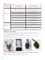
PROBLEM POSSIBLE CAUSE POSSIBLE SOLUTION
The infl ator
does not start
The infl ator
does not
infl ate
Power cable not properly
connected.
Undervoltage in battery.
Overvoltage in battery.
Hose wrong connection.
The ON button has not been pressed.
The safety fuse is blown.
Wrong pressure setting.
Switch not in START position.
The device is damaged
Connect the power cable correctly
and with the right polarity (red clamp
to battery positive terminal).
Check battery conditions.
Check battery conditions.
Connect the air hose to the
correct port.
Press the ON key.
Replace the fuse with one of the same
type (40 or 70 A).
Correct pressure setting.
Set main switches to ON and then
press START.
Contact a SCOPREGA service
centre.
10. TROUBLESHOOTING
10.1 ONLY FOR TURBOMAX KIT 12V and TURBOMAX KIT 24V-EV
1. Put the lids and the red grommets onto the cable ends (fi g. 1).
After crimping the faston, we recommend you to tin the cable end to the connector to ensure current
fl ow (fi g. 1 - arrow).
2. Insert the fastons into their seats, checking coupling tooth (fi g. 2) and polarity (fi g. 4).
3. Insert the grommets and the lids into their seats (fi g. 3).
ASSEMBLING THE CONNECTOR
POWER CABLE
The cable section of the on-board supply system should be suitable for its length:
4. For cable length up to 6 meters: 10 mm2 section
5. For cable length from 6 to 12 meters: 16 mm2 section

1
7
FASTENING THE INFLATOR
PREPARING THE INFLATION HOSE
The infl ator can be fastened onto the boat by means of the supplied “B” brackets (fi g. 5). Otherwise, it
can be wall-mounted after drilling a hole (fi g. 6), by fastening it to the “A” holes (fi g. 5) by means of Ø
4.5 mm self-threading screws. The maximum screw length inside the infl ator is 8 mm.
Cut the hose to the desired size. Insert the red fi tting into one of the hose ends to connect it to the
infl ator.
At the opposite end, insert and glue the soft PVC reduction unit. Then insert the valve fi tting, taking
care to select from the kit supplied the one that allows the valve to open fully.

1
8
INHALTSVERZEICHNIS
1. BESCHREIBUNG DER FUNKTIONSWEISE
2. VORWORT
3. VORWARNUNGEN
4. EINLEITUNG
5. EMPFOHLENE ANWENDUNGEN
6. TECHNISCHE DATEN
7. ALLGEMEINE SICHERHEITSREGELN
8. VERWENDUNG UND BETRIEB
9. ÜBERWACHUNG DES STATUS VON LUFTPUMPE
UND BATTERIE
10. PROBLEMABHILFE
8.1 ZUBEHÖR UND NETZKABEL
8.2 ANSCHLUSS UND ZUBEHÖR
8.3 ZUBEHÖR DER LUFTPUMPE
8.4 HINWEISE ZUM ZUBEHÖR
10.1 NUR BEI TURBOMAX KIT 12 V und TURBOMAX KIT 24 V-EV

1
9
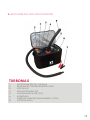
TURBOMAX
1. HAUPTSCHALTER (On-O / Start)
2. REGELKNOPF FÜR DRUCKEINSTELLUNG
3. STATUS-LED
4. EINLASSÖFFNUNG (IN)
5. AUSLASSANSCHLUSS (OUT)
6. SICHERUNG
7. KABEL MIT VERSORGUNGSKLEMMEN 12/24 V
8. LUFTSCHLAUCH
1. BESCHREIBUNG DER FUNKTIONSWEISE

2
0
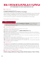
BETRIEBSANLEITUNG
BITTE BEWAHREN SIE DIESE ANLEITUNG GUT AUF
2. VORWORT
Sehr geehrte/r Kundin/Kunde,
herzlichen Glückwunsch zur Wahl von Scoprega.
Wir entwickeln und fertigen hochwertige Produkte, die den Bedürfnissen unserer Kunden
gerecht werden. Scoprega bietet auch einen hochqualitativen Kundendienst. Unsere
dafür zuständigen Abteilungen sichern Ihnen Beratung und vollständige technische
Unterstützung zu und geben im Bedarfsfall die erforderlichen Anweisungen.
Wir danken Ihnen für Ihr Vertrauen.
4. EINLEITUNG
Die TURBO MAX ist eine hoche ziente, tragbare elektrische Luftpumpe, die für Zuverlässigkeit und
Funktionalität steht. Die TURBO MAX ist mit zwei leistungsstarken Gleichstrommotoren ausgestattet,
die in Reihe geschaltete Turbinen antreiben, mit denen jeder Gegenstand auf einen Druck zwischen
175 und 250 mbar befüllt werden kann. Die Luftpumpe ist mit LEDs ausgestattet, die den Status der
Pumpe während des Betriebs anzeigen. Die Luftpumpe schaltet sich auf das Drücken der Taste ON
ein und dann automatisch aus, wenn der am Regelknopf (2) eingestellte Druck erreicht ist. Drückt der
Benutzer die Taste OFF stoppt das Gerät.
5. EMPFOHLENE ANWENDUNGEN
Großformatige aufblasbare Gegenstände (Schlauchboote / Zelte / Flöße).
Lesen Sie diese Anleitung vor der Verwendung der Luftpumpe. Die Nichtbeachtung
aller nachstehenden Anweisungen kann zu Schäden am Produkt und/oder zu schweren
Verletzungen von Personen führen.
ACHTUNG
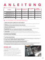
1. Befolgen Sie alle in diesem Dokument enthaltenen Anweisungen.
2. Bewahren Sie diese Anleitungen gut auf.
3. Versperren Sie die Einlassö nungen nicht (SIEHE ABBILDUNG AUF S. 3).
4. Schützen Sie stets das Netzkabel.
5. Ö nen Sie die Luftpumpe nie. Lassen Sie alle Wartungsarbeiten vom autorisierten, qualifi zierten
Wartungspersonal von Scoprega ausführen. Die Wartung ist notwendig, wenn das Gerät in irgendeiner
Weise beschädigt ist oder nicht funktioniert.
6. Nehmen Sie keine Manipulationen am Produkt vor. Das Ö nen der Luftpumpe hat den Verfall der
Garantie zur Folge.
7. Gewährleisten Sie eine angemessene Belüftung.
8. Vermeiden Sie es Gegenstände in der Nähe des Produkts abzustellen, während es in Betrieb steht.
9. Bewahren Sie das Produkt außerhalb der Reichweite von Kindern auf.
10. Die laufende Luftpumpe erzeugt Vibrationen. Um zu verhindern, dass sie herunterfällt, empfehlen
wir sie am Boden stehend zu verwenden.
3. VORWARNUNGEN
La page est en cours de chargement...
La page est en cours de chargement...
La page est en cours de chargement...
La page est en cours de chargement...
La page est en cours de chargement...
La page est en cours de chargement...
La page est en cours de chargement...
La page est en cours de chargement...
La page est en cours de chargement...
La page est en cours de chargement...
La page est en cours de chargement...
La page est en cours de chargement...
La page est en cours de chargement...
La page est en cours de chargement...
La page est en cours de chargement...
La page est en cours de chargement...
La page est en cours de chargement...
La page est en cours de chargement...
La page est en cours de chargement...
La page est en cours de chargement...
La page est en cours de chargement...
La page est en cours de chargement...
-
 1
1
-
 2
2
-
 3
3
-
 4
4
-
 5
5
-
 6
6
-
 7
7
-
 8
8
-
 9
9
-
 10
10
-
 11
11
-
 12
12
-
 13
13
-
 14
14
-
 15
15
-
 16
16
-
 17
17
-
 18
18
-
 19
19
-
 20
20
-
 21
21
-
 22
22
-
 23
23
-
 24
24
-
 25
25
-
 26
26
-
 27
27
-
 28
28
-
 29
29
-
 30
30
-
 31
31
-
 32
32
-
 33
33
-
 34
34
-
 35
35
-
 36
36
-
 37
37
-
 38
38
-
 39
39
-
 40
40
-
 41
41
-
 42
42


