Maytag Bravos MGDB200 Mode d'emploi
- Catégorie
- Sèche-linge électriques
- Taper
- Mode d'emploi

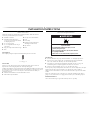
BRAVOS
®
FABRIC CARE
GAS DRYER
USE & CARE GUIDE
SÉCHEUSE À GAZ BRAVOS
®
AVEC
SYSTÈME DE SOIN DES TISSUS
GUIDE D’UTILISATION ET D’ENTRETIEN
FOR QUESTIONS ABOUT FEATURES, OPERATION/PERFORMANCE, PARTS, ACCESSORIES OR SERVICE
CALL: 1.800.688.9900
IN CANADA, CALL: 1.800.807.6777
AU CANADA, POUR ASSISTANCE, INSTALLATION OU SER
VICE, COMPOSEZ LE : 1.800.807.6777
VISIT OUR WEBSITE AT WWW.MAYTAG.COM
IN
CANADA, WWW.MAYTAG.CA
OU VISITEZ NOTRE SITE INTERNET À
WWW.MAYTAG.CA
.
W10201173A

2
TABLE OF CONTENTS
DRYER SAFETY..........................................................................................................................3
INSTALLATION INSTRUCTIONS .............................................................................................5
Tools and Parts....................................................................................................................... 5
Location Requirements ..........................................................................................................5
Electrical Requirements..........................................................................................................6
Gas Supply Requirements ...................................................................................................... 7
Venting Requirements............................................................................................................8
Plan Vent System..................................................................................................................10
Install Vent System ...............................................................................................................11
Install Leveling Legs .............................................................................................................11
Make Gas Connection..........................................................................................................12
Connect Vent .......................................................................................................................12
Level Dryer ..........................................................................................................................13
Reverse Door Swing.............................................................................................................13
Complete Installation ...........................................................................................................15
DRYER USE.............................................................................................................................. 16
Starting Your Dryer...............................................................................................................16
Stopping, Pausing, or Restarting ...........................................................................................17
Drying and Cycle Tips..........................................................................................................17
Status Lights.......................................................................................................................... 18
Cycles .................................................................................................................................. 18
Modifiers..............................................................................................................................19
Options ................................................................................................................................19
End Signal ............................................................................................................................ 20
Changing Cycles, Modifiers, and Options............................................................................20
Drying Rack Option .............................................................................................................20
DRYER CARE...........................................................................................................................22
Cleaning the Dryer Location ................................................................................................22
Cleaning the Lint Screen ......................................................................................................22
Cleaning the Dryer Interior...................................................................................................22
Removing Accumulated Lint................................................................................................ 22
Vacation, Storage and Moving Care.....................................................................................23
TROUBLESHOOTING.............................................................................................................23
Dryer Operation...................................................................................................................23
Dryer Results........................................................................................................................24
ASSISTANCE OR SERVICE.......................................................................................................26
In the U.S.A..........................................................................................................................26
In Canada.............................................................................................................................26
ACCESSORIES .........................................................................................................................26
WARRANTY ............................................................................................................................27
TABLE DES MATIÈRES
SÉCURITÉ DE LA SÉCHEUSE...................................................................................................28
INSTRUCTIONS D’INSTALLATION .......................................................................................31
Outillage et pièces ...............................................................................................................31
Exigences d’emplacement....................................................................................................31
Spécifications électriques .....................................................................................................32
Alimentation en gaz .............................................................................................................33
Exigences concernant l'évacuation ......................................................................................35
Planification du système d’évacuation .................................................................................36
Installation du système d’évacuation....................................................................................38
Installation des pieds de nivellement....................................................................................38
Raccordement au gaz...........................................................................................................39
Raccordement du conduit d’évacuation...............................................................................39
Réglage de l'aplomb de la sécheuse.....................................................................................39
Inversion du sens d'ouverture de la porte.............................................................................40
Achever l'installation............................................................................................................42
UTILISATION DE LA SÉCHEUSE.............................................................................................43
Mise en marche de la sécheuse............................................................................................43
Arrêt, pause ou remise en marche........................................................................................44
Conseils pour le séchage et les programmes ........................................................................44
Témoins lumineux................................................................................................................45
Programmes .........................................................................................................................45
Modificateurs .......................................................................................................................46
Options ................................................................................................................................47
End Signal (signal de fin de programme) ..............................................................................47
Changement des programmes, modificateurs, et options .....................................................47
Option de grille de séchage .................................................................................................48
ENTRETIEN DE LA SÉCHEUSE ................................................................................................49
Nettoyage de l'emplacement de la sécheuse........................................................................49
Nettoyage du filtre à charpie................................................................................................49
Nettoyage de l’intérieur de la sécheuse................................................................................49
Retrait de la charpie accumulée...........................................................................................50
Précautions à prendre avant les vacances, un entreposage ou un déménagement...............50
DÉPANNAGE ..........................................................................................................................51
Fonctionnement de la sécheuse ...........................................................................................51
Résultats de la sécheuse .......................................................................................................51
ASSISTANCE OU SERVICE......................................................................................................53
Au Canada ...........................................................................................................................53
ACCESSOIRES..........................................................................................................................53
GARANTIE...............................................................................................................................55

You can be killed or seriously injured if you don't immediately
You
can be killed or seriously injured if you don't
follow
All safety messages will tell you what the potential hazard is, tell you how to reduce the chance of injury, and tell you what can
happen if the instructions are not followed.
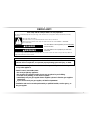
Your safety and the safety of others are very important.
We have provided many important safety messages in this manual and on your appliance. Always read and obey all safety
messages.
This is the safety alert symbol.
This symbol alerts you to potential hazards that can kill or hurt you and others.
All safety messages will follow the safety alert symbol and either the word “DANGER” or “WARNING.”
These words mean:
follow instructions.
instructions.
DANGER
WARNING
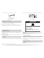
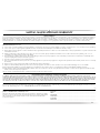
WARNING: For your safety, the information in this manual must be followed to minimize
the risk of fire or explosion, or to prevent property damage, personal injury, or death.
– Do not store or use gasoline or other flammable vapors and liquids in the vicinity of this
or any other appliance.
– WHAT TO DO IF YOU SMELL GAS:
•
Do not try to light any appliance.
•
Do not touch any electrical switch; do not use any phone in your building.
•
Immediately call your gas supplier from a neighbor's phone. Follow the gas supplier's
instructions.
•
If you cannot reach your gas supplier, call the fire department.
– Installation and service must be performed by a qualified installer, service agency, or
the gas supplier.
•
Clear the room, building, or area of all occupants.
3
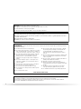
DRYER SAFETY

WARNING: Gas leaks cannot always be detected by smell.
Gas suppliers recommend that you use a gas detector approved by UL or CSA.
For more information, contact your gas supplier.
If a gas leak is detected, follow the “What to do if you smell gas” instructions.
In the State of Massachusetts, the following installation instructions apply:
■
Installations and repairs must be performed by a qualified or licensed contractor, plumber, or gasfitter qualified or licensed by
the State of Massachusetts.
■
If using a ball valve, it shall be a T-handle type.
■
A flexible gas connector, when used, must not exceed 3 feet.
IMPORTANT SAFETY INSTRUCTIONS
To reduce the risk of fire, electric shock, or injury to persons when using the dryer, follow basic precautions,
including the following:
WARNING:
■ Read all instructions before using the dryer.
■ Do not place items exposed to cooking oils in your dryer.
Items contaminated with cooking oils may contribute to
a chemical reaction that could cause a load to catch fire.
■ Do not dry articles that have been previously cleaned in,
washed in, soaked in, or spotted with gasoline, dry-
cleaning solvents, or other flammable or explosive
substances as they give off vapors that could ignite or
explode.
■ Do not allow children to play on or in the dryer. Close
supervision of children is necessary when the dryer is
used near children.
■ Before the dryer is removed from service or discarded,
remove the door to the drying compartment.
■ Do not reach into the dryer if the drum is moving.
■ Do not repair or replace any part of the dryer or attempt
any servicing unless specifically recommended in this
Use and Care Guide or in published user-repair
instructions that you understand and have the skills to
carry out.
■ Do not use fabric softeners or products to eliminate static
unless recommended by the manufacturer of the fabric
softener or product.
■ Do not use heat to dry articles containing foam rubber or
similarly textured rubber-like materials.
■ Clean lint screen before or after each load.
■ Keep area around the exhaust opening and adjacent
surrounding areas free from the accumulation of lint, dust,
and dirt.
SAVE THESE INSTRUCTIONS
■ The interior of the dryer and exhaust vent should be
cleaned periodically by qualified service personnel.
■ Do not install or store the dryer where it will be exposed
to the weather.
■ Do not tamper with controls.
■ See installation instructions for grounding requirements.
IMPORTANT: The gas installation must conform with local codes, or in the absence of local codes, with the National Fuel Gas
Code, ANSI Z223.1/NFPA 54 or the Canadian Natural Gas and Propane Installation Code, CSA B149.1.
The dryer must be electrically grounded in accordance with local codes, or in the absence of local codes, with the National
Electrical Code, ANSI/NFPA 70 or Canadian Electrical Code, CSA C22.1.
4

5
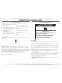
INSTALLATION INSTRUCTIONS
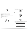
Tools and Parts
Gather the required tools and parts before starting installation. Read and follow the
instructions provided with any tools listed here.
■ Flat-blade screwdriver
■ Adjustable wrench that opens to
1" (2.5 cm) or hex-head socket wrench
(for
adjusting dryer feet)
■ 8" or 10" pipe wrench
■ 8" or 10" adjustable wrench (for gas
connections)
■ Pipe-joint compound resistant to LP gas
■ Pliers
■ Tin snips (new vent installation)
■ Level
■ Vent clamps
■ Caulking gun and compund (for
installing new exhaust vent)
■ Tape measure
■ Knife
Parts supplied:
Remove parts package from dryer drum. Check that all parts were included.
A
A. Leveling legs (4)
Parts needed:
Check local codes. Check existing electrical supply and venting and see “Electrical
Requirements” and “Venting Requirements” before purchasing parts.
Mobile home installations require metal exhaust system
hardware available for purchase from
the dealer from whom you purchased your dryer. For information on ordering, please refer to
the “Assistance or Service” section. You may also contact the dealer from whom you
purchased your dryer.
■ Mobile home installation kit. Ask for Part Number 346764.
■ Metal exhaust system hardware.
Location Requirements
WARNING
Explosion Hazard
Keep flammable materials and vapors, such as
gasoline, away from dryer.
Place dryer at least 18 inches (46 cm) above the floor
for a garage installation.
Failure to do so can result in death, explosion, or fire.
You will need
■ A location that allows for proper exhaust installation. See “Venting Requirements.”
■ If you are using a power supply cord, a grounded electrical outlet located within
2 ft (61 cm) of either side of the dryer
. See “Electrical Requirements.”
■ A sturdy floor to support the total weight (dryer and load) of 200 lbs (90.7 kg). The
combined weight of a companion appliance should also be considered.
■ A level floor with a maximum slope of 1" (2.5 cm) under entire dryer.
Do not operate your dryer at temperatures below 45ºF (7ºC). At lo
wer temperatures, the dryer
might not shut off at the end of an automatic cycle. Drying times can be extended.
The dryer must not be installed or stored in an
area where it will be exposed to water and/or
weather.
Check code requirements. Some codes limit, or do not permit, installation of the dryer in
garages, closets, mobile homes or sleeping quarters. Contact your local building inspector.
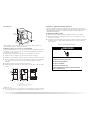
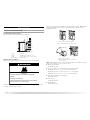
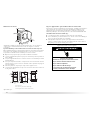
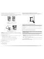
Installation Clearances
The location must be large enough to allow the dryer door to open fully.

6
Dryer Dimensions
43½"
(110.5 cm)
*27¼"
(74.3 cm)
22¼""
(56.5 cm)
29"
(73.7 cm)
*Most installations require a minimum 5" (12.7 cm) clearance behind the dryer for the
exhaust vent with elbow. See “Venting Requirements.”
Installation spacing for recessed area or closet installation
The following spacing dimensions are recommended for this dryer. This dryer has been tested
for spacing of 0" (0 cm) clearance on the sides and rear. Recommended spacing should be
considered for
the following reasons:
■ Additional spacing should be considered for ease of installation and servicing.
■ Additional clearances might be required for wall, door and floor moldings.
■ Additional spacing should be considered on all sides of the dryer to reduce noise transfer.
■ For closet installation, with a door, minimum ventilation openings in the top and bottom
of the door are required. Louvered doors with equivalent ventilation openings are
acceptable.
■ Companion appliance spacing should also be considered.
■ Additional spacing is required if you exhaust out the rear of the dryer to either the right or
left side.
A. Recessed area
B. Side view - closet or confined area
C. Closet door with vents
A
B
C
18"*
(45.7 cm)
1"
(2.5 cm)
29"
(73.7 cm)
1"
(2.5 cm)
1"*
(2.5 cm)
14" max.*
(35.6
cm)
27 ¼"
(69.2 cm)
5"
(12.7 cm)
48 in. *
(310 cm )
2
2
24 in. *
(155 cm )
2
2
3"*
(7.6 cm
)
3"*
(7.6 cm)
*Required spacing
Mobile home - Additional installation requirements
This dryer is suitable for mobile home installations. The installation must conform to the
Manufactured Home Construction and Safety Standard, Title 24 CFR, Part 3280 (formerly the
Federal Standard for Mobile Home Construction and Safety, Title 24, HUD Part 280) or
Standard CAN/CSA-Z240 MH.
Mobile home installations require:
■ Metal exhaust system hardware, which is available for purchase from your dealer.
■ Mobile Home Installation Kit Part Number 346764. See “Tools and Parts” section for
information on ordering.
■ Special provisions must be made in mobile homes to introduce outside air into the dryer.
The opening (such as a nearby window) should be at least twice as large as the dryer
exhaust opening.
Electrical Requirements
Electrical Shock Hazard
Plug into a grounded 3 prong outlet.
Do not remove ground prong.
Do not use an adapter.
Do not use an extension cord.
Failure to follow these instructions can result in death,
fire, or electrical shock.
WARNING
■ 120 Volt, 60 Hz., AC only, 15- or 20-amp fused electrical supply is required. A time-delay
fuse or circuit breaker is recommended. It is also recommended that a separate circuit

7
serving only this dryer be provided.
GROUNDING INSTRUCTIONS
SAVE THESE INSTRUCTIONS
■
For a grounded, cord-connected dryer:
This dryer must be grounded. In the event of malfunction or
breakdown, grounding will reduce the risk of electric shock
by providing a path of least resistance for electric current.
This dryer is equipped with a cord having an equipment-
grounding conductor and a grounding plug. The plug must
be plugged into an appropriate outlet that is properly
installed and grounded in accordance with all local codes
and ordinances.
WARNING:
Improper connection of the equipment-
grounding conductor can result in a risk of electric shock.
Check with a qualified electrician or service representative
or personnel if you are in doubt as to whether the dryer is
properly grounded. Do not modify the plug provided with the
dryer: if it will not fit the outlet, have a proper outlet installed
by a qualified electrician.
Gas Supply Requirements
WARNING
Explosion Hazard
Use a new CSA International approved gas supply line.
Install a shut-off valve.
Securely tighten all gas connections.
If connected to LP, have a qualified person make sure
gas pressure does not exceed 13" (33 cm) water
column.
Examples of a qualified person include:
licensed heating personnel,
authorized gas company personnel, and
authorized service personnel.
Failure to do so can result in death, explosion, or fire.
Gas Type
Natural Gas:
This dryer is equipped for use with Natural gas. It i
s design-certified by CSA International for
LP (propane or butane) gases with appropriate conversion.
■ Your dryer must have the correct burner for the type of gas in your home. Burner
information is located on the rating plate in the door well of your dryer. If this information
does not agree with the type of gas available, contact your dealer or call the phone
numbers referenced on the front page of this manual.
LP gas conversion:
Conversion must be made by a qualified technician.
No attempt shall be made to convert the appliance from the gas spec
ified on the model/serial
rating plate for use with a different gas without consulting your gas company. For information
on ordering an LP conversion kit, please refer to the “Assistance or Service” section. Ask for
Part Number 49572.
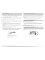
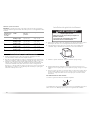
Gas Supply Line:
■ Must include
1
/8" NPT minimum plugged tapping accessible for test gauge connection,
immediately upstream of the gas connection to the dryer (see illustration).
■
1
/2" IPS pipe is recommended.
■
3
/8" approved aluminum or copper tubing is acceptable for lengths under 20 ft (6.1 m) if
local codes and gas supplier permit.
■ If you are using Natural gas, do not use copper tubing.
■
3
/8" flare x
3
/8" NPT adapter fitting between dryer pipe and
3
/8" approved tubing.
■ Lengths over 20 ft (6.1 m) should use larger tubing and a different size adapter fitting.
■ If your dryer has been converted to use LP gas,
3
/8" LP compatible copper tubing can be
used. If the total length of the supply line is more than 20 ft (6.1 m), use larger pipe.
NOTE: Pipe-joint compounds that resist the action of LP gas must be used. Do not use
TEFLON
®†
tape.
■ Must include a shutoff valve:
In the U.S.A.:
An individual manual shutoff valve must be
installed within six (6) feet (1.8 m) of the dryer
in accordance with the National Fuel Gas Code, ANSI Z223.1.
In Canada:
An individual manual shutoff valve must be installed in
accordance with the B149.1,
Natural Gas and Propane Installation Code. It is recommended that an individual manual
shutoff valve be installed within six (6) feet (1.8 m) of the dryer.

8
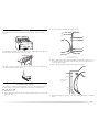
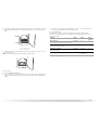
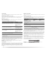
The location should be easy to reach for opening and closing.
A
B
E
D
C
A.
3
/8" flexible gas connector
B.
3
/8" pipe to flare adapter fitting
C.
1
/8" NPT minimum plugged tapping
D. ½" NPT gas supply line
E. Gas shutoff valve
Gas supply connection requirements
■ Use an elbow and a
3
/8" flare x
3
/8" NPT adapter fitting between the flexible gas connector
and the dryer gas pipe, as needed to avoid kinking.
■ Use only pipe-joint compound. Do not use TEFLON
®†
†®TEFLON is a registered trademark of E.I. Du Pont De Nemours and Company.
tape.
■ This dryer must be connected to the gas supply line with a listed flexible gas connector
that complies with the standard for connectors for gas appliances, ANSI Z21.24 or
CSA 6.10.
Burner Input Requirements:
Elevations above 10,000 ft (3,048 m):
■ When installed above 10,000 ft (3,048 m) a 4% reduction of the burner Btu rating shown
on the model/serial number plate is required for each 1,000 ft (305 m) increase in
elevation.
Gas Supply Pressure Testing
■ The dryer must be disconnected from the gas supply piping system during pressure testing
at pressures greater than ½ psi.
Dryer Gas Pipe
■ The gas pipe that comes out through the rear of your dryer has a
3
/8" male pipe thread.
A
2"
(5.1 cm)
³⁄₄"
(1.9 cm)
A.
3
/8" NPT dryer pipe
Venting Requirements
WARNING
Fire Hazard
Use a heavy metal vent.
Do not use a plastic vent.
Do not use a metal foil vent.
Failure to follow these instructions can result in death
or fire.
WARNING: To reduce the risk of fire, this dryer MUST BE EXHAUSTED OUTDOORS.
IMPORTANT:
Observe all governing codes and ordinances.
The dryer exhaust must not be connected into any gas vent, chimney, wall, ceiling, or a
concealed space of a building.
If using an existing vent system
■ Clean lint from the entire length of the system and make sure exhaust hood is not plugged
with lint.
■ Replace any plastic or metal foil vent with rigid or flexible heavy metal vent.
■ Review Vent system chart. Modify existing vent system if necessary to achieve the best
drying performance.
If this is a new vent system
Vent material
■ Use a heavy metal vent. Do not use plastic or metal foil vent.

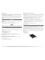
9
■ 4" (10.2 cm) heavy metal exhaust vent and clamps must be used.
4" (10.2 cm) heavy metal exhaust vent
4"
10.2 cm
Vent products can be purchased from your dealer or by calling Maytag Services. For more
information, see the “Assistance or Service” section.
Rigid metal vent
■ For best drying performance, rigid metal vents are recommended.
■ Rigid metal vent is recommended to avoid crushing and kinking.
Flexible metal vent
■ Flexible metal vents are acceptable only if accessible for cleaning.
■ Flexible metal vent must be fully extended and supported when the dryer is in its final
location.
■ Remove excess flexible metal vent to avoid sagging and kinking that may result in
reduced airflow and poor performance.
■ Do not install flexible metal vent in enclosed walls, ceilings or floors.
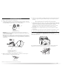
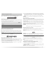
Elbows
45° elbows provide better airflow than 90° elbows.
Good Better
Clamps
■ Use clamps to seal all joints.
■ Exhaust vent must not be connected or secured with screws or other fastening devices
that extend into the interior of the duct. Do not use duct tape.
Clamp
Exhaust
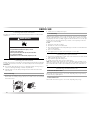
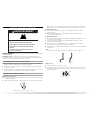
Recommended hood styles are shown here.
4"
(10.2 cm)
4"
(10.2 cm)
B
A
A. Louvered hood style
B. Box hood style
The angled hood style (shown here) is acceptable.
4"
(10.2 cm)
2½"
(6.4 cm)
■ An exhaust hood should cap the vent to keep rodents and insects from entering the home.
■ Exhaust hood must be at least 12" (30.5 cm) from the ground or any object that may be in
the path of the exhaust (such as flowers, rocks or bushes, snow line, etc.).
■ Do not use an exhaust hood with a magnetic latch.
Improper venting can cause moisture and lint to collect
indoors, which may result in:
Moisture damage to woodwork, furniture, paint, wallpaper,
carpets, etc.
Housecleaning problems and health problems.

10
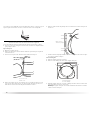
Plan Vent System
Choose your exhaust installation type
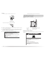
Recommended exhaust installations
Typical installations vent the dryer from the rear of the dryer.
A
B
B
C
D
E
F
G
H
A. Dryer
B. Elbow
C. Wall
D. Exhaust hood
E. Clamps
F. Rigid metal or flexible metal vent
G. Vent length necessary to connect elbows
H. Exhaust outlet
Optional exhaust installations
Venting systems come in many varieties. Select the type best for your installation.
WARNING
Fire Hazard
Cover unused exhaust hole with the following kit:
8212503
Contact your local dealer.
Failure to follow these instructions can result in death,
fire, electrical shock, or serious injury.
This dryer can be converted to exhaust out the bottom. If you prefer, you may contact your
local dealer to have the dryer converted.
This dryer can also be exhausted from the rear to either the right or left side. Optional kits for
these
exhaust installations are needed. Refer to the manufacturer’s instructions for kit
installation instructions.
A
B
A. Standard rear offset exhaust installation
B. Rear exhaust installation to the right or left side
C
D
C. Bottom exhaust installtion
D. Over-the-top installation
(also available with
one offset elbow)
NOTE: The following kits for close clearance alternate installations are available for purchase.
Please see the “Assistance or Service” section to order.
■ Over-the-Top Installation:
Part Number 4396028
■ Periscope Installation (For use with dryer vent to wall vent mismatch):
Part Number 4396037 - 0" (0 cm) to 18" (45.72 cm) mismatch
Part Number 4396011 - 18" (45.72 cm) to 29" (73.66 cm) mismatch
Part Number 4396014 - 29" (73.66 cm) to 50" (127 cm) mismatch
■ Rear exhaust installation to left or right side:
Part Number 4396011
■ Vent extension:
Part Number 8544761
■ Bottom Exhaust:
Part Number 8212503

11
Special provisions for mobile home installations
The exhaust vent must be securely fastened to a n
oncombustible portion of the mobile home
structure and must not terminate beneath the mobile home. Terminate the exhaust vent
outside.
Determine vent path
■ Select the route that will provide the straightest and most direct path outdoors.
■ Plan the installation to use the fewest number of elbows and turns.
■ When using elbows or making turns, allow as much room as possible.
■ Bend vent gradually to avoid kinking.
■ Use the fewest 90° turns possible.
Determine vent length and elbows needed for best drying performance
■ Use the following Vent system chart to determine type of vent material and hood
combinations acceptable to use.
NOTE: Do not
use vent runs longer than those specified in the Vent system chart.
Exhaust systems longer than those specified will:
■ Shorten the life of the dryer.
■ Reduce performance, resulting in longer drying times and increased energy usage.
The Vent system chart provides venting requirements that will help to achieve the best drying
p
erformance.
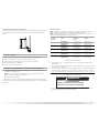
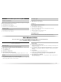
Vent system chart
NOTE: Performance of rear exhaust to either side of the dryer is equivalent to adding one
elbow. To determine maximum exhaust length, add one elbow to the chart.
NOTE: Bottom
exhaust performance is equivalent to adding two elbows. To determine
maximum exhaust length, add one elbow to the chart.
Number of
90º turns
or elbows
Type o f
vent
Box or
Louvered
hoods
Angled
hoods
0 Rigid metal
Flexible metal
100 ft (30.5 m)
72 ft (21.9 m)
94 ft (28.7 m)
64 ft (19.5 m)
1 Rigid metal
Flexible metal
90 ft (27.4 m)
67 ft (20.4 m)
84 ft (25.6 m)
59 ft (18 m)
2 Rigid metal
Flexible metal
80 ft (24.4 m)
63 ft (19.2 m)
74 ft (22.6 m)
55 ft (16.8 m)
3 Rigid metal
Flexible metal
71 ft (21.6 m)
61 ft (18.6 m)
65 ft (19.8 m)
53 ft (16.2 m)
4 Rigid metal
Flexible metal
63 ft (19.2 m)
59 ft (18 m)
57 ft (17.4 m)
51 ft (15.5 m)
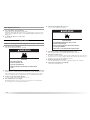
Install Vent System
1. Install exhaust hood. Use caulking compound to seal exterior wall opening around
exhaust hood.
2. Connect vent to exhaust hood. Vent must fit inside exhaust hood. Secure vent to exhaust
hood with 4" (10.2 cm) clamp.
3. Run v
ent to dryer location. Use the straightest path possible. See “Determine vent path” in
“Plan Vent System.” Avoid 90º turns. Use clamps to seal all joints. Do not use duct tape,
screws or other fastening devices that extend into the interior of the vent to secure vent.
Install Leveling Legs
WARNING
Excessive Weight Hazard
Use two or more people to move and install dryer.
Failure to do so can result in back or other injury.
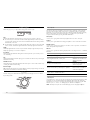
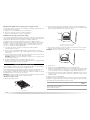
1. To protect the floor, use a large, flat piece of cardboard from the dryer carton. Place
cardboard under the entire back edge of the dryer.

12
2. Firmly grasp the body of the dryer (not the top or console panel). Gently lay the dryer on
the cardboard. See illustration.
3. Examine the leveling legs. Find the diamond marking.
4. Screw the legs into the leg holes by hand. Use a wrench to finish turning the legs until the
diamond marking is no longer visible.
5. Place a
carton corner post from dryer packaging under each of the 2 dryer back corners.
Stand the dryer up. Slide the dryer on the corner posts until it is close to its final location.
Leave enough room to connect the exhaust vent.
For mobile home use
Gas dryers must be securely fastened to the floor.
Mobile home installations require a Mobile Home Installation Kit. See “Tools and Parts”
section for information on ordering.
Make Gas Connection
1. Remove the red cap from the gas pipe.
2. Using a wrench to tighten, connect the gas supply to the dryer. Use pipe-joint compound
on the threads of all non-flared male fittings. If flexible metal tubing is used, be sure there
are no kinks.
A
B
A. Flared male thread
B. Non-flared male thread
NOTE: For LP gas connections, you must use pipe-joint compound resistant to the action
of LP gas. Do not use TEFLON
®†
tape.
†®TEFLON is a registered trademark of E.I. Du Pont De Nemours and Company.
A combination of pipe fittings must be used to connect the dryer to the existing gas line.
Shown is a recommended connection. Your connection may be different, according to the
supply line type, size and location.
A
B
C
D
A.
3
/8" flexible gas connector
B.
3
/8" dryer pipe
C.
3
/8" to
3
/8" pipe elbow
D.
3
/8" pipe-to-flare adapter fitting
3. Open the shutoff valve in the supply line. The valve is open when the handle is parallel to
the gas pipe.
A. Closed valve
B. Open valve
A
B
4. Test all connections by brushing on an approved noncorrosive leak-detection solution.
Bubbles will show a leak. Correct any leak found.
Connect Vent
1. Using a 4" (10.2 cm) clamp, connect vent to exhaust outlet in dryer. If connecting to
existing vent, make sure the vent is clean. The dryer vent must fit over the dryer exhaust
outlet and inside the exhaust hood. Check that the vent is secured to exhaust hood with a
4" (10.2 cm) clamp.
2. Move dryer into its final location. Do not crush or kink vent.
3. (On gas models) Check that there are no kinks in the flexible gas line.
4. On
ce the exhaust vent connection is made, remove the corner posts and cardboard.

13
Level Dryer
Check the levelness of the dryer by first placing a level on the top of the dryer near the
console.
Then, by placing a level in the crease on the side of the dryer between the top of the dryer and
the dryer cabinet, check the levelness from front to back.
If the dryer is not level, prop up the dryer using a wood block. Use a wrench to adjust the legs
up or down and check again for levelness.
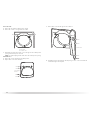
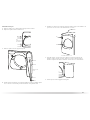
Reverse Door Swing
You can change your door swing from a right-side opening to a left-side opening, if desired.
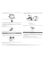
1. Place a towel or soft cloth on top of the dryer or work space to protect the surface.
Remove the door assembly
1. Open th
e dryer door.
2. Remove the bottom screw from each of the 2 hinges that attach the dryer door to the front
panel of the dryer.
3. Loosen the top screw from each of the 2 hinges in Step 2.
A
B
A
B
A. Loosen these screws.
B. Remove these screws.
4. Remove the dryer door and the hinges by lifting upward on the door. Lay the door on a
flat, protected surface, with the inside of the door facing up. Remove remaining 2 loose
screws from
dryer front panel.
5. Re
move the 4 plastic plugs located outside the dryer door opening.
Location of plastic
p
lugs shown
6. Install 4 plastic plugs into screw holes in the dryer left where the hinges were removed in
Step 4.

14
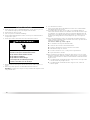
Reverse the strike
1. Remove the door strike from the dryer door opening.
2. Remo
ve the cosmetic cover opposite the door strike.
A
B
A. Door strike
B. Cosmetic cover
3. Reinstall the door strike and cosmetic cover on the opposite side of the dryer door
opening from where they were removed.
NOTE:
Door strike and plugs must be on the same side of the dryer door opening.
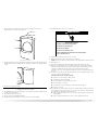
Reinstall the door
1. Rem
ove the 4 screws and 2 hinges from the dryer door.
2. Repla
ce the 4 screws in the same holes.
Screw & hinge
locations
3. Remove the 4 screws from the opposite side of the door.
Screw locatons
4. Install the 2 hinges to the front panel of the dryer using 4 screws. Use the non-slotted side
to attach the hinge to the front panel.

15
5. Install screws in the top hinge holes in the door. Do not tighten screws. Leave
approximately ¼" (5 mm) of screw exposed.
A
A
A. Install these screws first.
6. Hang door by placing screw heads into top slotted holes of hinges and slide door down.
Align bottom screw holes in hinge and door. Install two bottom screws. Tighten all hinge
screws.
7. Close door to engage door strike.
Complete Installation
1. Check that all parts are now installed. If there is an extra part, go back through the steps to
see which step was skipped.
2. Ch
eck that you have all of your tools.
3. Dispose of/rec
ycle all packaging materials.
4. Check the dryer’s final location. Be sure the vent is not crushed or kinked.
5. Chec
k that the dryer is level. See “Level Dryer.”
Electrical Shock Hazard
Plug into a grounded 3 prong outlet.
Do not remove ground prong.
Do not use an adapter.
Do not use an extension cord.
Failure to follow these instructions can result in death,
fire, or electrical shock.
WARNING
6. Plug into a grounded 3 prong outlet. Turn on power.
7. Re
move any protective film or tape remaining on the dryer.
NOTE: Glass door models have a protective film on the window that should be removed.
8. Re
ad “Dryer Use.”
9. W
ipe the dryer drum interior thoroughly with a damp cloth to remove any dust.
10. If
you live in a hard water area, use of a water softener is recommended to control the
buildup of scale through the water system in the dryer. Over time, the buildup of lime
scale may clog different parts of the water system, which will reduce product
performance. Excessive scale buildup may lead to the need for certain part replacement
or repair.
11. T
est dryer operation by selecting a Timed Dry heated cycle and starting the dryer. For this
test, do not select the Air Fluff modifier.
If the dryer will not start, check the following:
■ Controls are set in a running or “On” position.
■ Start button has been pushed firmly.
■ Dryer is plugged into a grounded 3 prong outlet.
■ Electrical supply is connected.
■ Household fuse is intact and tight, or circuit breaker has not tripped.
■ Dryer door is closed.
12. When
the dryer has been running for 5 minutes, open the dryer door and feel for heat. If
you feel heat, cancel cycle and close door. If you do not feel heat, turn off the dryer and
check that the gas supply line shutoff valve is open.
■ If the gas supply line shutoff valve is closed, open it, then repeat the 5-minute test as
outlined above.
■ If the gas supply line shutoff valve is open, contact a qualified technician.

16
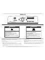
DRYER USE
Starting Your Dryer
WARNING
Explosion Hazard
Keep flammable materials and vapors, such as
gasoline, away from dryer.
Do not dry anything that has ever had anything
flammable on it (even after washing).
Failure to follow these instructions can result in death,
explosion, or fire.
WARNING
Fire Hazard
No washer can completely remove oil.
Do not dry anything that has ever had any type of oil on
it (including cooking oils).
Items containing foam, rubber, or plastic must be dried
on a clothesline or by using an Air Cycle.
Failure to follow these instructions can result in death
or fire.
WARNING: To reduce the risk of fire, electric shock, or injury to persons, read the
IMPORTANT SAFETY INSTRUCTIONS before operating this appliance.
This manual covers several different models. Your dry
er may not have all of the cycles and
features described.
Follow these basic steps to start your dryer. Please refer to specific sections of this manual for
more detailed information.
1. Clean
lint screen before each load. See “Cleaning the Lint Screen.”
NOTE: Y
our Maytag
®
dryer is equipped with an “Auto Wake-Up” feature. You may also
press any button (except Drum Light), turn the knob to select cycle, or open the dryer
door and the display will illuminate. If the dryer is not started within 5 minutes, the dryer
will turn off the display.
2. Place laundry in dry
er and shut door.
3. Press PO
WER/CANCEL.
4. Turn the knob to the selected cycle. The preset settings for Sensor, or Timed Cycles will
illuminate. The estimated (sensor cycle) or actual (timed) cycle time (in minutes) will
show in the display.
NOTE: A de
fault time is displayed when an automatic cycle is selected. During the first
few minutes of the drying process, the cycle time may automatically vary from the default
time based on the size and fabric type of the load. Toward the end of the drying process,
the estimated time display will adjust again, showing the final drying time.

17
To use a Sensor Cycle
■ Press POWER/CANCEL.
■ Turn the knob to desired Sensor Cycle.
■ Select DRYNESS LEVEL to adjust how dry you want the load. As the cycle runs, the
control senses the dryness of the load and adjusts the time automatically for the
selected dryness level.
The initial preset temperature is the prefered sett
ing for drying loads of different
garment types listed (see “Sensor Cycles”). If desired, one alternate temperature may
be selected to dry the load on a lower heat setting. The next time the same cycle is
selected, the alternate temperature is remembered and displayed. The original
(default) temperature may be reselected. The Delicate cycle does not offer an alternate
temperature.
■ Select the desired Options.
To make changes during a Sensor Cycle:
■ Press START/PAUSE.
■ Adjust Dryness Level.
NOTE: Dryness selections can be made only while using Sensor Cycles.
How the Sensi-Care™ Drying System Works
Moisture-sensing strips and temperature sensor
s inside the dryer drum monitor how fast
the load is drying, how hot the air should be, and when clothes are dry. The system
automatically stops the cycle to help save time and avoid overdrying.
To use a Timed Cycle
■ Turn knob to desired Timed Cycle.
■ Press the TIME ADJUST + (plus) or – (minus) until the desired drying time is displayed.
Press the + (plus) or – (minus) and the time will change by 1-minute intervals. Press
and hold the + (plus) or – (minus) and the time will change by 5-minute intervals.
NOTE: T
he Time Adjust feature can be used only with the Timed Cycles.
■ Press TEMP LEVEL until the desired temperature illuminates.
NOTE: The Temp Level feature can be used only with Timed Cycles.
NOTE: During
a Timed Cycle, you can change the settings for Time, Temp, the Wrinkle
Prevent setting, and the End Signal.
5. (OPTIONAL STEP) If desired, select OPTIONS. For more details, see “Options.”
6. (OPTION
AL STEP) If desired, press END
SIGNAL. A signal will sound to alert you when a
cycle ends. For more details, see “End Signal.”
7. Press START/PAUSE. Be sure the door is closed.
■ If you do not press Start within 5 minutes of selecting the cycle, the dryer
automatically shuts off.
■ If you wish to end your drying cycle after pressing Start, press POWER/CANCEL.
Stopping, Pausing, or Restarting
To stop or pause your dryer at any time
Open the door or press START/PAUSE. Press POWER/CANCEL to cancel a cycle.
To restart the dryer
Close the door. Press START/PAUSE until dryer starts.
NOTE: Dryi
ng will continue from where the cycle was interrupted if you close the door and
press Start within 5 minutes. If the cycle is interrupted for more than 5 minutes, the dryer will
shut
off. Select new cycle settings before restarting the dryer.
Drying and Cycle Tips
Select the correct cycle and dryness level or temperature for your load. If a Sensor Cycle is
running, the display shows the estimated cycle time when your dryer is automatically sensing
the dryness level of your load. If a Timed Cycle is running, the display shows the exact
number of minutes remaining in the cycle.
Cool Down tumbles the load without
heat during the last few minutes of all cycles. Cool
Down makes the loads easier to handle and reduces wrinkling. The length of the Cool Down
depends on the load size and dryness level.
Drying tips
■ Follow care label directions when they are available.
■ If desired, add a fabric softener sheet. Follow package instructions.
■ To reduce wrinkling, remove the load from the dryer as soon as tumbling stops. This is
especially important for permanent press, knits, and synthetic fabrics.
■ Avoid drying heavy work clothes together with lighter fabrics. This could cause
overdrying of lighter fabrics and lead to increased shrinkage or wrinkling.
Cycle tips
■ Dry most loads using the preset cycle settings.
■ Refer to the Sensor, or Timed Preset Cycle Settings chart (in the “Cycles” section) for a
guide to drying various loads.
■ Drying temperature and dryness level are preset when you choose a Sensor Dry
Cycle. You can select a different dryness level, depending on your load, by pressing
DRYNESS LEVEL and choosing More, Normal, Less, or Damp. The initial preset
temperature is the preferred setting; however, you may select an alternate drying
temperature by pressing TEMP LEVEL. Once selected, the new heat setting will be
retained until reset to the initial preset temperature. The Delicate cycle does not allow
an alternate temp to be selected.
■ If you wish to adjust the cycle length of a Timed Cycle, press TIME ADJUST + (plus) or
– (minus). Adjust the temperature of a Timed Cycle by pressing TEMP LEVEL until the
desired temperature is selected.
NOTE:
You cannot choose a dryness level with Timed Cycles.

18
Status Lights
Follow the progress of your dryer with the drying Status indicator lights.
Wet
The Wet light illuminates at the beginning of a Sensor Cycle if a wet item is detected.
■ In a Sensor Cycle, if a wet item is not detected after approximately 5 minutes, the dryer
goes directly into Cool Down. The Cool Down and the Wrinkle Prevent setting indicators
will illuminate, if selected.
■ In a Timed Cycle, wet items are not detected. The dryer will continue to run for the length
of time selected, and the Wet light will illuminate. The Damp light will not illuminate.
Damp
The Damp light illuminates in a Sensor Cycle when the laundry is approximately 80% dry.
Damp Dry signal beeps, if selected. See “Options.”
Cool Down
The Cool Down light illuminates during the Cool Down part of the cycle. Laundry cools for
ease in handling.
Dry
The Dry light illuminates when the drying cycle is finished. This indicator stays on during the
Wrinkle Prevent setting.
Wrinkle Prevent
The Wrinkle Prevent setting light illuminates when this option is selected. This indicator stays
on during the Wrinkle Prevent setting.
Indicator lights
Other indicator lights show Cycle, Modifiers, Options, and Cycle Signal settings selected. The
display shows the estimated or actual time remaining.
Cycles
Select the drying cycle that matches the type of load you are drying. See Sensor or Timed
Cycle Settings charts.
Sensor Cycles
Sensor Cycles allow you to match the cycle to the load you are drying. See the following
Sensor Preset Cycle Settings chart. Each cycle dries certain fabrics at the recommended
temperature. A sensor detects the moisture in the load and automatically adjusts the drying
time for optimal drying. An alternate temperature is selectable for all cycles with the
exception of the Delicate by pressing the TEMP LEVEL button.
Heavy Duty
Use this cycle to get regular heat for heavyweight mixed loads, cottons, and jeans.
Normal
Use this cycle to get medium heat for drying sturdy fabrics such as work clothes and sheets.
Wrinkle Control
Use this cycle to get low heat for drying no-iron fabrics, such as sport shirts, casual business
clothes, and permanent press blends.
Delicate
Use this cycle to get extra-low heat to gently dry items such as lingerie, blouses, or washable
knit fabrics.
Sensor Preset Cycle Settings
Sensor Cycles Load Type Temperature
HEAVY DUTY
Heavyweight mixed loads, cottons, jeans
Regular*
Medium heat is selectable as an
alternate temperature.
NORMAL
Corduroys, work clothes, sheets
Medium*
Low heat is selectable as an
alternate temperature.
WRINKLE CONTROL
Business casual clothes, permanent press, synthetics
Low*
Extra-low heat is selectable as
an alternate temperature.
DELICATE
Lingerie, blouses, washable knit fabrics
Extra-Low
*Preferred setting
Timed Cycles
Use Timed Cycles to select a specific amount of drying time and a drying temperature. When
a Timed Cycle is selected, the Estimated Time Remaining display shows the actual time
remaining in your cycle. You can change the actual time in the cycle by pressing the TIME
ADJUST + (plus) or – (minus). See “Changing Cycles, Modifiers, and Options.”
NOTE: Timed Cycles may also be used with the drying rack. See “Drying Rack Option.”

19
Timed Dry
Use this cycle to complete drying if items are still damp after a Sensor Cycle. Timed Dry is
also useful for drying heavyweight and bulky items, such as bedspreads, and work clothes.
Lightweight garments, such as exercise wear, can be dried using Timed Dry on a low
temperature setting. Timed Dry can also be used with the drying rack.
Rapid Dry
Use this cycle for dying small loads that need short drying time.
Freshen Up
Use this cycle to help smooth out wrinkles from such items as clothes packed in suitcases or
items wrinkled from being left in the dryer to long.
Timed Preset Cycle Settings
Timed Cycles
Load Type
Default
Temperature
Default Time
(Minutes)
TIMED DRY
Heavyweight, bulky items, work
clothes
High 40
RAPID DRY
Small loads
Regular 23
FRESHEN UP
Helps to smooth out wrinkles
Medium 20
Modifiers
Sensor Cycle Modifiers
Use the DRYNESS LEVEL button to select dryness levels for the Sensor Cycles. Press DRYNESS
LEVEL until the desired Dryness setting illuminates.
The preset dryness setting is Normal when a Sensor Cycle is
selected. You can select a
different Dryness Level, depending on your load, by pressing DRYNESS LEVEL and choosing
More, Normal, Less, or Damp. Selecting More, Normal, Less, or Damp automatically adjusts
the Dryness Level at which the dryer will shut off. Once a Dryness Level is set, it cannot be
changed without stopping the cycle.
The initial preset temperature is the preferred setting for drying clothes; however, if desired,
one alternate
temperature may be selected to dry the load on a lower heat setting. Once the
alternate temperature has been selected, the next time the same cycle is selected, the
alternate temperature is remembered and displayed. The original (default) temperature may
be reselected. The Delicate cycle does not offer an alternate temperature.
NOTE: Dryness Level selections cannot be used with the Timed Cycle.
Timed Cycle Modifiers
Use the TEMP LEVEL button to select temperatures for the Timed Cycles. Press TEMP LEVEL
until the desired temperature setting illuminates.
Air Fluff
Use the Air Fluff Modifier for items that require drying without heat such as rubber, plastic,
and heat-sensitive fabrics. This table shows examples of items that can be dried using Air
Fluff.
Type of Load Time*
(Minutes)
Foam rubber - pillows, padded bras, stuffed toys 20 - 30
Plastic - Shower curtai
ns, tablecloths 20 - 30
Rubber-backed rugs 40 - 50
Olefin, polypropylene, sheer nylon 10 - 20
*Reset cycle to complete drying, if needed.
When using Air Fluff
■ Check that coverings are securely stitched.
■ Shake and fluff pillows by hand periodically during the cycle.
■ Dry item completely. Foam rubber pillows are slow to dry.
NOTE:
Air Fluff is not available with Sensor Cycles.
Options
You can customize your cycles by selecting options.
Wrinkle Prevent Setting
The Wrinkle Prevent setting helps keep wrinkles from forming when you cannot unload the
dryer promptly at the end of a cycle. During this option, the dryer stops tumbling and then
tumbles again for a brief period.
■ Press WRINKLE PREVENT setting to get up to 90 minutes of heat-free, periodic tumbling
at the end of a cycle.
■ Stop the Wrinkle Prevent at any time by pressing WRINKLE PREVENT setting or opening
the dryer door.
■ For the Wrinkle Control cycle, the Wrinkle Prevent setting is preset to ON. The other
Sensor Cycles will retain the Wrinkle Prevent setting. For example, if you select the
Wrinkle Prevent setting in the Normal cycle, the Wrinkle Prevent setting will be on the
next time you select the Normal cycle.
NOTE: If you do not select the Wrinkle Prevent setting, the dryer stops after cool down.

20
Damp Dry Signal
Select the Damp Dry Signal to alert you that your clothes are approximately 80% dry. This is
useful when you want to remove lightweight items in a mixed load to avoid overdrying or
remove partially dry items that may need ironing.
The Damp Dry Signal is useful w
hen drying bedsheets/linens in a mixed load. When the
signal goes off, open the door to stop the dryer, rearrange the load inside the dryer, close the
door, and restart the dryer to finish the drying cycle. Rearranging the load will aid in the
drying process.
NOTE: T
he Damp Dry Signal is available only with the Sensor Cycles.
End Signal
End Signal
The End Signal produces an audible sound when the drying cycle is finished. Promptly
removing clothes at the end of the cycle reduces wrinkling.
Press END SIGNAL until the desired volume (High, Low, or Off) is selected.
NOTE: When the Wrinkle Prevent setting is selected and the End Signal is on, the tone will
sound every 5 minutes until the clothes are removed, or the
Wrinkle Prevent setting ends.
Changing Cycles, Modifiers, and Options
You can change Sensor and Timed Cycles, Modifiers, and Options anytime before pressing
Start.
■ Three short tones sound if an unavailable combination is selected. The last selection will
not be accepted.
Changing Cycles after pressing Start
1. Press POWER/CANCEL.
2. Select the desired cycle and options.
3. Press ST
ART/PAUSE. The dryer starts at the beginning of the new cycle.
NOTE: If y
ou do not press Start/Pause within 5 minutes of selecting the cycle, the dryer
automatically shuts off.
Changing Modifiers and Options after pressing Start
You can change an Option or Modifier anytime before the selected Option or Modifier
begins.
1. Press START/PAUSE.
2. Select the new Option and/or Modifier.
3. Press ST
ART/PAUSE to continue the cycle.
Changing the Preset Dryness Level Settings
If all of your loads on all Sensor cycles are consistently not as dry as you would like, you may
change the preset Dryness Level settings to increase the dryness. This change will affect all of
your Sensor cycles.
Your Dryness Level settings can be
adjusted to adapt to different installations, environmental
conditions, or personal preference. There are 3 drying settings: 1 (factory preset dryness
lev
el), 2 (slightly dryer clothes, approximately
15% more drying time), and 3 (much dryer
clothes, approximately 30% more drying time).
1. T
he Dryness Level settings cannot be changed while the dryer is running.
2. Press and hold the
DRYNESS LEVEL button for 5 seconds. The dryer will beep, and “CF”
will be displayed for 1 second followed by the current Dryness Level setting.
3. T
o select a new Dryness Level setting, press the DRYNESS LEVEL button again until the
desired Dryness Level setting is shown.
NOTE: While cycling through the settings, the current setting will not flash, but the other
settings will flash.
4. Press ST
ART/PAUSE to save the Dryness Level setting.
5. T
he Dryness Level setting you selected will become your new preset Dryness Level setting
for all Sensor cycles.
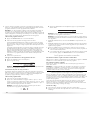
Drying Rack Option
Use the Drying Rack to dry items such as sweaters and pillows without tumbling. The drum
turns, but the drying rack does not move.
If your model does not have a drying rack, you may be able to purchase one for your model.
T
o find out whether your model allows drying rack usage and for information on ordering,
please refer to the front page of the manual or contact the dealer from whom you purchased
your dryer.
NOTE: T
he drying rack must be removed for normal tumbling. Do not use the automatic cycle
with the drying rack.
To use the drying rack
1. Open dryer door.
A
A. Front edge
La page est en cours de chargement...
La page est en cours de chargement...
La page est en cours de chargement...
La page est en cours de chargement...
La page est en cours de chargement...
La page est en cours de chargement...
La page est en cours de chargement...
La page est en cours de chargement...
La page est en cours de chargement...
La page est en cours de chargement...
La page est en cours de chargement...
La page est en cours de chargement...
La page est en cours de chargement...
La page est en cours de chargement...
La page est en cours de chargement...
La page est en cours de chargement...
La page est en cours de chargement...
La page est en cours de chargement...
La page est en cours de chargement...
La page est en cours de chargement...
La page est en cours de chargement...
La page est en cours de chargement...
La page est en cours de chargement...
La page est en cours de chargement...
La page est en cours de chargement...
La page est en cours de chargement...
La page est en cours de chargement...
La page est en cours de chargement...
La page est en cours de chargement...
La page est en cours de chargement...
La page est en cours de chargement...
La page est en cours de chargement...
La page est en cours de chargement...
La page est en cours de chargement...
La page est en cours de chargement...
La page est en cours de chargement...
-
 1
1
-
 2
2
-
 3
3
-
 4
4
-
 5
5
-
 6
6
-
 7
7
-
 8
8
-
 9
9
-
 10
10
-
 11
11
-
 12
12
-
 13
13
-
 14
14
-
 15
15
-
 16
16
-
 17
17
-
 18
18
-
 19
19
-
 20
20
-
 21
21
-
 22
22
-
 23
23
-
 24
24
-
 25
25
-
 26
26
-
 27
27
-
 28
28
-
 29
29
-
 30
30
-
 31
31
-
 32
32
-
 33
33
-
 34
34
-
 35
35
-
 36
36
-
 37
37
-
 38
38
-
 39
39
-
 40
40
-
 41
41
-
 42
42
-
 43
43
-
 44
44
-
 45
45
-
 46
46
-
 47
47
-
 48
48
-
 49
49
-
 50
50
-
 51
51
-
 52
52
-
 53
53
-
 54
54
-
 55
55
-
 56
56


Maytag Bravos MGDB200 Mode d'emploi
- Catégorie
- Sèche-linge électriques
- Taper
- Mode d'emploi
dans d''autres langues
- English: Maytag Bravos MGDB200 User guide