Aritech ACA 001 Mounting instructions
- Catégorie
- Kits de voiture
- Taper
- Mounting instructions

ACA 001
Aritech - ISO 9001
© Aritech 1 001.06.96
Il est également recommandé dinstaller un signal explicatif à proximité
du lecteur.
Suggestion de texte: APPUYEZ SUR LE BOUTON POUR OUVRIR.
Instructions de montage
- Retirez la partie frontale (fig. 2.01) du boîtier à laide dun tournevis.
- Retirez la vis (fig. 3.01).
- Servez-vous du bloc de commutation (fig. 3.02) comme gabarit pour
marquer les emplacements de trous de vis sur le mur (fig. 4).
- Insérez le câble à travers louverture (fig. 3.03) du bloc de commutation.
- Si nécessaire, retirez une des percées (fig. 3.04).
- Fixez le bloc de commutation au mur.
- Dénudez les fils du câble et raccordez-les au bornier comme indiqué
ci-dessous.
- Vérifiez toutes les connexions.
- Replacez le boîtier sur le bloc de commutation.
- Serrez la vis.
- Replacez la partie frontale sur le boîtier.
- Testez le fonctionnement du dispositif.
Connexion du câble (fig. 5)
Le câble est raccordé aux bornes marquées Ü (fig. 5.01) et P
(fig. 5.02). En cas dutilisation dun câble de 0,2 mm, pliez la partie
nue du câble comme indiqué.
- Enfoncez et maintenez le contact à ressort (fig. 5.03).
- Introduisez lextrémité du câble dans lorifice de la borne.
- Relâchez le contact à ressort.
Données techniques
Dimensions en mm (HxLxP) 63 x 63 x 35 mm
Poids 250 g
Nederlands
Montagevoorschriften Aritech ACA 001 Uitgangsknop
Voor meer informatie over het Aritech Toegangscontrole Systeem, zie de
Hardware Handleiding, doc. nr. $.
Veiligheidsvoorschriften
n Neem altijd de veiligheidsvoorschriften in acht die in uw land gelden.
Lees onderstaande veiligheidsvoorschriften aandachtig door voordat u
het product installeert.
n Schakel de netspanning uit en verbreek de accuverbinding met de
controller voordat u de installatie wijzigt.
n Schakel de netspanning niet in wanneer het deksel is verwijderd.
Schakel de netspanning pas in wanneer alle installatieprocedures zijn
uitgevoerd.
n Dek de voedingseenheid niet af.
Dit kan tot oververhitting leiden.
n Zorg ervoor dat u bij het installeren geen onderdelen of schroeven
forceert.
De inhoud van de verpakking controleren
n De verpakking bevat:
1 ACA 001 Uitgangsknop
1 Montagevoorschrift
De knop plaatsen (fig. 1)
De uitgangsknop wordt naast de deur in het beveiligde gebied geplaatst.
Aanbevolen montagehoogte: ongeveer: 120 cm vanaf de grond.
Wij raden u aan om een bordje met uitleg naast de lezer te plaatsen.
Bijvoorbeeld: DRUK OP DE KNOP OM DE DEUR TE OPENEN
Montagevoorschriften
- Verwijder het voorste gedeelte (fig. 2.01) van de behuizing met een
schroevendraaier.
- Verwijder de schroef (fig. 3.01).
- Gebruik het schakelaarblok (fig. 3.02) als aftekenmal om de
schroefgaten op de muur te markeren (fig. 4).
- Haal de kabel door de opening (fig. 3.03) in het schakelaarblok.
- Indien nodig, verwijder één van de uitbreekpoorten (fig. 3.04).
- Bevestig het schakelaarblok op de muur.
- Strip de kabeldraden en sluit ze aan op de klemmen zoals hieronder
beschreven.
- Controleer alle verbindingen.
- Plaats de behuizing terug op het schakelaarblok.
- Draai de schroef vast.
- Plaats het voorste gedeelte van de behuizing terug.
- Test of de knop juist functioneert.
De kabel aansluiten (fig. 5)
Sluit de kabel aan op de klemmen met Ü (fig. 5.01) en P (fig. 5.02).
Indien 0,2 mm kabel wordt gebruikt, vouw dan het blanke gedeelte
van de kabel zoals aangegeven.
English
Mounting Instructions Aritech ACA 001 Request-to-exit device
For additional information on the Aritech Access Control system refer to
the Hardware Manual, doc. nr. $.
Safety instructions
n Always observe the safety regulations applicable in your country. Read
the following safety instructions before attempting to install the product.
n Before disassembling the product, disconnect the power supply unit
from the controller.
n When the cover has been removed, never connect the power supply
unit to the mains. Only connect when all installation procedures have
been completed.
n Never cover the power supply unit as this may cause it to overheat.
n When installing, do not force any parts or screws.
Checking the package contents
n The package contains:
1 ACA 001 Request-to-exit device
1 Mounting instructions sheet
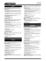
Siting the device (fig. 1)
The request-to-exit device is installed next to a door in the secured area.
Recommended mounting height: approx. 120 cm from the ground. It is
recommended to mount an explanatory sign next to the reader.
Suggested text: PRESS BUTTON TO OPEN.
Mounting instructions
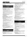
- Remove the front part (fig. 2.01) from the housing using a screwdriver.
- Remove the screw (fig. 3.01).
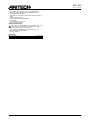
- Use the switching block (fig. 3.02) as a template for marking the screw
hole locations on the wall (fig. 4).
- Enter the cable through the opening (fig. 3.03) in the switching block.
- If required, remove one of the break-outs (fig. 3.04).
- Fasten the switching block to the wall.
- Strip the cable wires and connect them to the terminals as described
below.
- Check all connections.
- Reinstall the housing on the switching block.
- Tighten the screw.
- Reinstall the front part on the housing.
- Test the operation of the device.
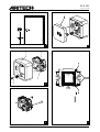
Connecting the cable (fig. 5)
The cable is connected to the terminals marked Ü (fig. 5.01) and P
(fig. 5.02). If 0.2 mm cable is used, fold the blank part of the cable
as shown.
- Press and hold the spring button (fig. 5.03).
- Insert the cable end into the terminal hole.
- Release the spring button.
Technical data
Size in mm (HxWxD) 63 x 63 x 35 mm
Weight 250 g
Français
Instructions de montage du Dispositif de demande de sortie Aritech ACA 001
Pour de plus amples informations quant au système de contrôle daccès
Aritech, consultez le Manuel du Matériel, doc. n° $.
Directives de sécurité
n Observez toujours les règlements de sécurité en vigueur dans votre
pays. Lisez les directives de sécurité suivantes avant dentreprendre
linstallation du produit.
n Avant de démonter le produit, débranchez du contrôleur le bloc
dalimentation électrique.
n Ne branchez jamais le bloc dalimentation électrique si le couvercle a
été retiré. Branchez uniquement si toutes les procédures dinstallation
ont été effectuées.
n Ne jamais couvrir le bloc dalimentation électrique car il risque de
surchauffer.
n Lors de linstallation, ne forcez aucune pièce ou vis.
Vérification du contenu de lemballage
n Lemballage contient:
1 Dispositif de demande de sortie ACA 001
1 Fiche dinstructions de montage
Installation du dispositif (fig. 1)
Le dispositif de demande de sortie est installé à proximité dune porte
dans la zone de sécurité. Hauteur de montage recommandée: à environ
120 cm du sol.

ACA 001
Aritech - ISO 9001
Aritech reserves the right to change specifications without notice. 2 001.06.96
- Druk de veerknop in en houd deze ingedrukt (fig. 5.03).
- Steek het uiteinde van de kabel in het gat van de klem.
- Laat de veerknop los.
Technische gegevens
Afmetingen in mm (HxBxD) 63 x 63 x 35 mm
Gewicht 250 g
Deutsch
Montageanweisungen Aritech-Ausgangsknopf ACA 001
Für nähere Informationen über das Aritech-Zutrittskontrollsystem wird auf
das Hardware-Handbuch, Dok.-Nr. $, verwiesen.
Sicherheitsvorschriften
n Beachten Sie immer die in Ihrem Land gültigen
Sicherheitsvorschriften. Lesen Sie die folgenden Sicherheitshinweise,
bevor Sie versuchen, das Produkt zu installieren.
n Unterbrechen Sie vor dem Demontieren des Produktes die
Stromversorgung des Controllers.
n Schließen Sie die Stromversorgungseinheit niemals an das Netz an,
wenn die Abdeckung entfernt ist. Der Netzanschluß darf nur dann
erfolgen, wenn alle Installationsverfahren vollständig durchgeführt
worden sind.
n Bedecken Sie niemals die Stromversorgungseinheit, da dies zu einer
Überhitzung führen kann.
n Wenden Sie beim Installieren keine übermäßige Gewalt an. Eine
Überbeanspruchung der Teile oder Schrauben ist nicht zulässig.
Überprüfen des Inhaltes der Verpackung
n Die Verpackung enthält:
1 Ausgangsknopf ACA 001
1 Montageanweisungen
Installieren des Knopfes (Abb. 1)
Der Ausgangsknopf wird neben einer Tür in dem gesicherten Bereich
installiert. Empfohlene Montagehöhe: ca. 120 cm über dem Boden. Es
empfiehlt sich, eine Erläuterung neben dem Leser anzubringen.
Textvorschlag: ZUM ÖFFNEN KNOPF DRÜCKEN.
Montageanweisungen
- Entfernen Sie den vorderen Teil (Abb. 2.01) des Gehäuses mit Hilfe
eines Schraubenziehers.
- Entfernen Sie die Schraube (Abb. 3.01).
- Verwenden Sie den Schalterblock (Abb. 3.02) als Schablone zum
Markieren der Schraublochpositionen auf der Wand (Abb. 4).
- Führen Sie das Kabel durch die Öffnung (Abb. 3.03) in den
Schalterblock ein.
- Stechen Sie gegebenenfalls eins der vorbereiteten Löcher (Abb. 3.04)
durch.
- Befestigen Sie den Schalterblock an der Wand.
- Isolieren Sie das Kabel ab und schließen Sie die Drähte, wie unten
beschrieben, an die Anschlußklemmen an.
- Überprüfen Sie alle Anschlüsse.
- Bringen Sie das Gehäuse wieder auf dem Schalterblock an.
- Ziehen Sie die Schraube an.
- Bringen Sie den vorderen Teil des Gehäuses wieder an.
- Überprüfen Sie die Funktion des Knopfes.
Anschließen des Kabels (Abb. 5)
Das Kabel wird an den Anschlußklemmen mit den Markierungen Ü
(Abb. 5.01) und P (Abb. 5.02) angeschlossen.
Wenn ein 0,2-mm-Kabel verwendet wird, so ist der abisolierte
Teil des Kabels, wie gezeigt wird, zu falten.
- Drücken Sie den Federknopf und halten Sie ihn eingedrückt (Abb. 5.03).
- Stecken Sie das Kabelende in das Loch der Klemme.
- Lassen Sie den Federknopf wieder los.
Technische Daten
Maße in mm (HxBxT) 63 x 63 x 35 mm
Gewicht 250 g
Italiano
Istruzioni di montaggio Dispositivo di Richiesta Uscita Aritech ACA 001
Per ulteriori informazioni in merito al sistema di controllo dellaccesso
Aritech, si rimanda al manuale Hardware, doc. n. $.
Norme di sicurezza
n Rispettare sempre le norme di sicurezza in vigore nel paese duso.
Leggere le seguenti norme di sicurezza prima di procedere al
montaggio del prodotto.
n Prima di smontare il prodotto, scollegare lunità di controllo
dallalimentatore elettrico.
n Una volta rimosso il coperchio, non collegare mai lalimentatore
elettrico alla rete. Procedere al collegamento solo dopo aver
completato tutte le operazioni di montaggio.
n Non ricoprire mai lalimentatore elettrico, onde evitare
surriscaldamenti.
n Durante il montaggio, non forzare i componenti o le viti.
Verifica del contenuto dellimballaggio
n Limballaggio contiene:
1 Dispositivo di Richiesta Uscita ACA 001
1 Foglio di istruzioni di montaggio
Ubicazione del dispositivo (fig. 1)
Il dispositivo di richiesta uscita viene installato accanto ad una porta
nellaria protetta. Altezza di montaggio consigliata: circa 120 cm da terra.
Si raccomanda di collocare accanto al lettore un cartello esplicativo, con
eventuale dicitura: PER APRIRE PREMERE IL PULSANTE.
Istruzioni di montaggio
- Staccare la parte frontale (fig. 2.01) della scatola utilizzando un
cacciavite.
- Togliere la vite (fig. 3.01).
- Utilizzando il blocco di commutazione (fig. 3.02) come sagoma
tracciare lubicazione dei fori per le viti sulla parete (fig. 4).
- Inserire il cavo attraverso lapertura (fig. 3.03) sita nel blocco di
commutazione.
- Se necessario, perforare una delle borchie stampate (fig. 3.04).
- Fissare il blocco di commutazione sul muro.
- Denudare un tratto di cavo e collegare i conduttori alla morsettiera
procedendo come di seguito descritto.
- Verificare tutti i collegamenti.
- Collocare la scatola sul blocco di commutazione.
- Stringere la vite.
- Rimontare la parte frontale sulla scatola.
- Collaudare il funzionamento del dispositivo.
Collegamento del cavo (fig. 5)
I conduttori del cavo vanno collegati ai morsetti contrassegnati Ü
(fig. 5.01) e P (fig. 5.02). Se si utilizza un cavo da 0.2 mm, piegare
il tratto nudo del cavo come indicato.
- Premere il pulsante a pressione e tenerlo premuto (fig. 5.03).
- Inserire lestremità del conduttore nel foro del morsetto.
- Rilasciare il pulsante a pressione.
Caratteristiche tecniche
Dimensioni in mm (HxLxP) 63 x 63 x 35 mm
Peso 250 g
Svenska
Monteringsanvisningar för Aritech ACA 001 utgångsknapp
För vidare information om Aritech passersystem, se
installationsmanualen, dok. nr. $.
Installationsanvisning
n Kontrollera alltid gällande säkerhetsföreskrifter.
n Läs alltid nedanstående installationsanvisning innan produkten skall
installeras.
n Bryt spänningsmatningen till kortläsaren innan arbete påbörjas.
n Koppla ej till spänningsmatningen till kortläsaren innan kortläsaren är
monterad på montageplattan. Spänningsmatningen får endast kopplas
till när installationen är utförd.
n Övertäckning av strömförande komponenter i kortläsaren kan orsaka
överhettning.
n Använd aldrig våld eller felaktiga verktyg vid installation det kan skada
produkten.
Kontroll av förpackningens innehåll
n Förpackningen innehåller:
1 ACA 001 utgångsknapp
1 Monteringsanvisning
Placering av utrustningen (fig. 1)
Utgångsknappen monteras bredvid dörren innanför säkerhetsområdet.
Rekommenderad monteringshöjd: 120 cm från golvet. Vi rekommenderar
att montera en förklarande skylt bredvid knappen. Förslag till påskrift:
FÖR ATT ÖPPNA, TRYCK IN KNAPPEN.
Monteringsanvisningar
- Ta av fronten (fig. 2.01) från höljet med hjälp av en skruvmejsel.
- Ta bort skruven (fig. 3.01).
- Använd kopplingsplattan (fig. 3.02) som en mall vid markering av
skruvhålens placering på väggen (fig. 4).

ACA 001
Aritech - ISO 9001
© Aritech 3 001.06.96
- För in kabeln genom öppningen (fig. 3.03) i kopplingsplattan.
- Avlägsna en av utbrytningarna om det är nödvändigt (fig. 3.04).
- Fäst kopplingsplattan på väggen.
- Skala kablarna och anslut dem till kabelfästena enligt beskrivningen
nedan.
- Kontrollera alla anslutningar.
- Montera tillbaka höljet på kopplingsplattan.
- Dra åt skruven.
- Montera tillbaka fronten på höljet.
- Testa att knappen fungerar.
Anslutning av kabeln (fig. 5)
Kabeln ansluts till de kabelfästen som är markerade Ü (fig. 5.01)
och P (fig. 5.02). Om installationen sker med 0.2 mm kablar,
ska den skalade kabeln vikas enligt figuren.
- Tryck och håll den fjäderbelastade knappen intryckt (fig. 5.03).
- För in kabeländen i kabelfästets hål.
- Släpp upp knappen.
Tekniska data
Mått i mm (HxBxD) 63 x 63 x 35 mm
Vikt 250 g

ACA 001
Aritech - ISO 9001
Aritech reserves the right to change specifications without notice. 4 001.06.96
4
5
1 2
3
3
4
1
2
-
 1
1
-
 2
2
-
 3
3
-
 4
4


Aritech ACA 001 Mounting instructions
- Catégorie
- Kits de voiture
- Taper
- Mounting instructions
dans d''autres langues
- italiano: Aritech ACA 001
- English: Aritech ACA 001
- Deutsch: Aritech ACA 001
- Nederlands: Aritech ACA 001
- svenska: Aritech ACA 001
Documents connexes
Autres documents
-
Interlogix 50’ Antimasking High Security Sensor Mirror Optic PIR Guide d'installation
-
Wilo Wilo-Control EC-L Installation And Operating Instructions Manual
-
 Tweco Robotics QRC™-2000 Nozzle Cleaning Station Guide d'installation
-
 Tweco Robotics QRC™-2000 Nozzle Cleaning Station Guide d'installation
-
 Tweco TWECO® FUSION™250 Air-Cooled Mig Gun 250 AMP Manuel utilisateur
-
Dedicated Micros BX2 Guide d'installation
-
 Firepower Firepower® FP 95 Flux Cored Welder Manuel utilisateur
-
Tamron A08 Manuel utilisateur


