Indesit SWDD 129 EU Mode d'emploi
- Catégorie
- Sèche-linge
- Taper
- Mode d'emploi

GB
1
English,1
Contents
Installation, 2-3-4-5
Unpacking and levelling
Connecting the electricity and water supplies
The first wash cycle
Technical data
Instructions for the fitter
Care and maintenance, 6
Cutting off the water or electricity supply
Cleaning the washer dryer
Cleaning the detergent dispenser drawer
Caring for the door and drum of your appliance
Cleaning the pump
Checking the water inlet hose
Precautions and tips, 7
General safety
Disposal
Opening the porthole door manually
Description of the washer dryer, 8-9
Control panel
Display
How to run a wash cycle or a drying cycle, 10
Wash cycles and functions, 11
Table of wash cycles
Wash functions
Detergents and laundry, 12
Detergent dispenser drawer
Preparing the laundry
Special wash cycles
Load balancing system
Troubleshooting, 13
Service, 14
GB
SWDD 129
Instructions for use
WASHER DRYER
ES
Español,29Français,15
F
Italiano,43
I
! This symbol reminds you to read this instruction
manual.

2
GB
Installation
! This instruction manual should be kept in a safe
place for future reference. If the washer dryer is
sold, transferred or moved, make sure that the
instruction manual remains with the machine so
that the new owner is able to familiarise himself/
herself with its operation and features.
! Read these instructions carefully: they contain
vital information relating to the safe installation
and operation of the appliance.
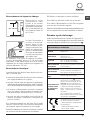
Unpacking and levelling
Unpacking
1. Remove the washer dryer from its packaging.
2. Make sure that the washer dryer has not been
damaged during the transportation process. If it
has been damaged, contact the retailer and do not
proceed any further with the installation process.
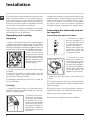
3. Remove the 4 pro-
tective screws (used
during transportation)
and the rubber washer
with the corresponding
spacer, located on the
rear part of the applian-
ce (see figure).
4. Close off the holes using the plastic plugs
provided.
5. Keep all the parts in a safe place: you will
need them again if the washer dryer needs to
be moved to another location.
! Packaging materials should not be used as
toys for children.
Levelling
1. Install the washer dryer on a flat sturdy floor,
without resting it up against walls, furniture ca-
binets or anything else.
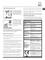
2. If the floor is not per-
fectly level, compensa-
te for any unevenness
by tightening or loo-
sening the adjustable
front feet (see figure);
the angle of inclination,
measured in relation to
the worktop, must not
exceed 2°.
Levelling the machine correctly will provide it with
stability, help to avoid vibrations and excessive
noise and prevent it from shifting while it is ope-
rating. If it is placed on carpet or a rug, adjust
the feet in such a way as to allow a sufficient
ventilation space underneath the washer dryer.
Connecting the electricity and wa-
ter supplies
Connecting the water inlet hose
1. Connect the supply
pipe by screwing it to
a cold water tab using
a ¾ gas threaded con-
nection (see figure).
Before performing the
connection, allow the
water to run freely until
it is perfectly clear.
2. Connect the inlet
hose to the washer dr-
yer by screwing it onto
the corresponding wa-
ter inlet of the applian-
ce, which is situated on
the top right-hand side
of the rear part of the
appliance (see figure).
3. Make sure that the hose is not folded over
or bent.
! The water pressure at the tap must fall within
the values indicated in the Technical details table
(see next page).
! If the inlet hose is not long enough, contact a
specialised shop or an authorised technician.
! Never use second-hand hoses.
! Use the ones supplied with the machine.

GB
3
65 - 100 cm
Connecting the drain hose
Connect the drain
hose, without bending
it, to a drainage duct or
a wall drain located at a
height between 65 and
100 cm from the floor;
alternatively, rest it on
the side of a washba-
sin or bathtub, faste-
ning the duct supplied
to the tap (see figure).
The free end of the
hose should not be
underwater.
! We advise against the use of hose extensions;
if it is absolutely necessary, the extension must
have the same diameter as the original hose and
must not exceed 150 cm in length.
Electrical connections
Before plugging the appliance into the electricity
socket, make sure that:
•thesocketis earthed andcomplieswith all
applicable laws;
•thesocketisabletowithstandthemaximum
power load of the appliance as indicated in the
Technical data table (see opposite);
•thepowersupplyvoltagefallswithinthevalues
indicated in the Technical data table (see opposite);
•thesocketiscompatiblewiththeplugofthe
washer dryer. If this is not the case, replace the
socket or the plug.
! The washer dryer must not be installed ou-
tdoors, even in covered areas. It is extremely
dangerous to leave the appliance exposed to
rain, storms and other weather conditions.
! When the washer dryer has been installed, the
electricity socket must be within easy reach.
! Do not use extension cords or multiple sockets.
! The cable should not be bent or compressed.
! The power supply cable must only be replaced
by authorised technicians.
Warning! The company shall not be held responsible
in the event that these regulations are not respected.
The first wash cycle
Once the appliance has been installed, and before
you use it for the first time, run a wash cycle with
detergent and no laundry, using the wash cycle .
Technical data
Model
SWDD 129
Dimensions
width 59,5 cm
height 81,5 cm
depth 54,5 cm
Capacity
from 1 to 7 kg for the wash
programme
from 1 to 5 kg for the drying
programme
Electrical
connections
please refer to the technical
data plate fixed to the ma-
chine
Water con-
nections
maximum pressure 1 MPa
(10 bar)
minimum pressure 0.05
MPa (0.5 bar)
drum capacity 52 litres
Spin speed
up to 1200 rotations per
minute
Energy ra-
ted
programmes
according to
regulation
EN 50229
Wash: programme ;
temperature 60°C (1st press
of the button); using a load of
7 kg.
Drying: the smaller load
must be dried by selecting
the “IRON DRY” dryness le-
vel. The load must consist of
2 sheets, 1 pillowcase and 1
hand towel;
the remainder of the load
must be dried by selecting
the “CUPBOARD DRY” dry-
ness level.
This appliance conforms to
the following EC Directives:
- 2004/108/EC (Electromagne-
tic Compatibility)
- 2006/95/EC (Low Voltage)
- 2012/19/EU - WEEE

4
GB
Instructions for the fitter
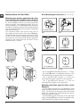
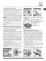
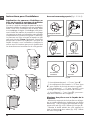
Mounting the wooden panel onto the door
and inserting the machine into cabinets:
In the case where the machine must be shipped
for final installation after the wooden panel has
been mounted, we suggest leaving it in its ori-
ginal packaging. The packaging was designed
to make it possible to mount the wooden panel
onto the machine without removing it completely
(see figures below).
The wooden panel that covers the face of
the machine must not be less than 13 mm in
thickness and can be hinged on either the right
or left. For the sake of practicality when using
the machine, we recommend that the panel be
hinged on the same side as the door for the
machine itself - the left.
A
B
C
D
E
Tur seite
Door Mounting Accessories (Fig. 1-2-3-4-5).
Fig. 1
N° 2 Hinges
N° 1 Magnet N° 1 Magnet plate
N° 1 Rubber plug
N° 2 Hinge Supports
N° 4 Spacers
Fig. 2
Fig. 3 Fig. 4
Fig. 5
Fig. 4/B
- No. 6 type A self-threading screws, l =13 mm.
- No. 2 type B metric, countersunk screws, l =25;
for fastening the magnet plate to the cabinet.
- No. 4 type C metric screws, l =15 mm; for
mounting the hinge supports to the cabinet.
- No. 4 type D metric screws, l =7 mm; for
mounting the hinges on the supports.
Mounting the Parts onto the Face of the
Machine.
- Fit the hinge supports to the appliance front
panel, positioning the hole marked with an arrow
in fig. 1 so that it is on the inner side of the front
panel. Fit a spacer (fig. 4/B) between the surfa-
ces using type C screws.
- Fit the magnet plate at the top of the opposite
side, using type B screws to fix two spacers (fig.
4/B) between the plate and the surface.

GB
5
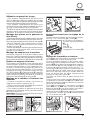
Using the Drilling Template.
- To trace the positions of the holes on the left-
hand side of the panel, align the drilling template
to the top left side of the panel using the lines
traced on the extremities as a reference.
- To trace the positions of the holes on the right-
hand side of the panel, align the drilling template
to the top right side of the panel.
- Use an appropriately sized router to mill the holes
for the two hinges, the rubber plug and the magnet.
Mounding the Parts onto the Wooden Panel
(Door).
- Insert the hinges into the holes (the movable part of
the hinge must be positioned facing away from the
panel) and fasten them with the 4 type A screws.
- Insert the magnet into the top hole on the op-
posite side of the hinges and fasten it with the
two type B screws.
- Insert the rubber plug into the bottom hole.
The panel is now ready to be mounted onto the
machine.
Mounting the Panel into the machine.
Insert the nib of the hinge (indicated by the arrow
in fig. 2) into the hole for the hinge and push the
panel towards the front of the machine. Fasten
the two hinges with the type D screws.
Fastening the plinth guide.
If the machine is installed at the end of a set of
modular cabinets, mount either one or both of
the guides for the base molding (as shown in fig.
8). Adjust them for depth based on the position
of the base molding, and, if necessary, fasten
the base to the guides (fig. 9).
This is how to assemble the plinth guide (fig. 8):
Fasten angle P using screw R, insert plinth guide
Q into the special slot and once it is in the desired
position, lock it in place using angle P and screw R.
Inserting the machine into the Cabinet.
- Push the machine into the opening, aligning it
with the cabinets (fig. 6).
- Regulate the adjustable feet to raise the ma-
chine to the appropriate height.
- To adjust the position of the wooden panel in
both the vertical and horizontal directions, use
the C and D screws, as shown in fig. 7.
Important: close the lower part of the appliance
front by ensuring that the plinth rests against the floor.
Fig. 8 Fig. 9
Accessories provided for the height
adjustment.
The following can be found inside the polystyrene
lid (fig. 10): 2 crossbars (G), 1 strip (M)
the following can be found
inside the appliance drum:
4 additional feet (H),
4 screws (I),
4 screws (R),
4 nuts (L),
2 plinth guides (Q)
Adjusting the appliance height.
The height of the appliance can be adjusted (from
815 mm to 835 mm), by turning the 4 feet.
Should you require the appliance to be placed
higher than the above height, you need to use the
following accessories to raise it to up to 870 mm:
The two crossbars (G); the 4 feet (H); the 4 screws (I); the
4 nuts (L) then perform the following operations (fig. 11):
remove the 4 original feet, place a crossbar G at
the front of the appliance, fastening it in place
using screws I (screwing them in where the ori-
ginal feet were) then insert the new feet H.
Repeat the same operation at the back of the appliance.
Now adjust feet H to raise or lower the appliance
from 835 mm to 870 mm.
Once you have reached the desired height, lock
nuts L onto crossbar G.
To adjust the appliance to a height between 870
mm and 900 mm, you need to mount strip M,
adjusting feet H to the required height.
Insert the strip as follows:
loosen the three screws N situated at the front of
the Top cover of the appliance, insert strip M as
shown in fig. 12, then fasten screws N.
D
C
C
570
min
815
540
595
820 ÷ 900
600 min
Fig. 6 Fig. 7
L
I
H
G
M
Fig. 11 Fig. 12
Fig. 10

6
GB
Care and maintenance
Cutting off the water and electri-
city supplies
•Turnoffthewatertapaftereverywashcycle.
This will limit wear on the hydraulic system
inside the washer dryer and help to prevent
leaks.
•Unplugthewasherdryerwhencleaningit
and during all maintenance work.
Cleaning the washer dryer
The outer parts and rubber components of the
appliance can be cleaned using a soft cloth
soaked in lukewarm soapy water. Do not use
solvents or abrasives.
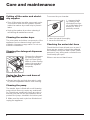
Cleaning the detergent dispenser
drawer
Remove the dispenser
by raising it and pul-
ling it out (see figure).
Wash it under running
water; this operation
should be repeated
frequently.
Caring for the door and drum of
your appliance
•Alwaysleavetheportholedoorajarinorder
to prevent unpleasant odours from forming.
Cleaning the pump
The washer dryer is fitted with a self-cleaning
pump which does not require any maintenan-
ce. Sometimes, small items (such as coins or
buttons) may fall into the pre-chamber which
protects the pump, situated in its bottom part.
! Make sure the wash cycle has finished and
unplug the appliance.
1
2
To access the pre-chamber:
1. unscrew the lid
by rotating it anti-
clockwise (see figu-
re): a little water may
trickle out. This is
perfectly normal;
2. clean the inside thoroughly;
3. screw the lid back on;
Checking the water inlet hose
Check the inlet hose at least once a year. If
there are any cracks, it should be replaced
immediately: during the wash cycles, water
pressure is very strong and a cracked hose
could easily split open.
! Never use second-hand hoses.

GB
7
Precautions and tips
! This washer dryer was designed and constructed in ac-
cordance with international safety regulations. The following
information is provided for safety reasons and must therefore
be read carefully.
General safety
•Thisappliancewasdesignedfordomesticuseonly.
• This appliance can be used by children aged
from 8 years and above and persons with re-
duced physical, sensory or mental capabilities
or lack of experience and knowledge if they
have been given supervision or instruction
concerning use of the appliance in a safe way
and understand the hazards involved. Children
shall not play with the appliance. Cleaning and
user maintenance shall not be made by children
without supervision.
- Do not dry unwashed items in the tumble dryer.
- Items that have been soiled with substances such as cooking
oil, acetone, alcohol, petrol, kerosene, spot removers, turpentine,
waxes and wax removers should be washed in hot water with
an extra amount of detergent before being dried in the tumble
dryer.
- Items such as foam rubber (latex foam), shower caps, water-
proof textiles, rubber backed articles and clothes or pillows fitted
with foam rubber pads should not be dried in the tumble dryer.
- Fabric softeners, or similar products, should be used as spe-
cified by the fabric softener instructions.
- The final part of a tumble dryer cycle occurs without heat
(cool down cycle) to ensure that the items are left at a tem-
perature that ensures that the items will not be damaged.
WARNING: Never stop a tumble dryer before the end of the
drying cycle unless all items are quickly removed and spread
out so that the heat is dissipated.
•Donottouchthemachinewhenbarefootorwithwetor
damp hands or feet.
•Donotpullonthepowersupplycablewhenunplugging
the appliance from the electricity socket. Hold the plug and
pull.
•Do not open thedetergentdispenserdrawer while the
machine is in operation.
•Donottouchthedrainedwaterasitmayreachextremely
high temperatures.
•Neverforcetheportholedoor.Thiscoulddamagethesafety
lock mechanism designed to prevent accidental opening.
•Iftheappliancebreaksdown,donotunderanycircum-
stances access the internal mechanisms in an attempt to
repair it yourself.
•Alwayskeepchildrenwellawayfromtheappliancewhile
it is operating.
•Thedoorcanbecomequitehotduringthewashcycle.
•Iftheappliancehastobemoved,workinagroupoftwo
or three people and handle it with the utmost care. Never
try to do this alone, because the appliance is very heavy.
•Beforeloadinglaundryintothewasherdryer,makesure
the drum is empty.
• Duringthedryingphase,thedoortendstogetquitehot.
• Donotusetheappliancetodryclothesthathavebeen
washed with flammable solvents (e.g. trichlorethylene).
• Donotusetheappliancetodryfoamrubberorsimilar
elastomers.
• Makesurethatthewatertapisturnedonduringthedrying
cycles.
Disposal
•Disposingofthepackagingmaterials:observelocalregu-
lations so that the packaging may be re-used.
• TheEuropeanDirective-2012/19/EU-WEEEonWaste
Electrical and Electronic Equipment, requires that old hou-
sehold electrical appliances must not be disposed of in the
normal unsorted municipal waste stream. Old appliances
must be collected separately in order to optimise the recovery
and recycling of the materials they contain and reduce the
impact on human health and the environment. The crossed
out “wheeled bin” symbol on the product reminds you of
your obligation, that when you dispose of the appliance it
must be separately collected. Consumers should contact
their local authority or retailer for information concerning the
correct disposal of their old appliance.
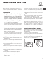
Opening the porthole door manually
In the event that it is not possible to open the porthole door
due to a powercut, and if you wish to remove the laundry,
proceed as follows:
1. remove the plug from the electrical socket.
2. make sure the water level inside the machine is lower than
the door opening; if it is not, remove excess water using the
drain hose, collecting it in a bucket.
3. pull outwards using the tab as indicated in the figure, until
the plastic tie-rod is freed from its stop position; pull down-
wards and open the door at the same time.

8
GB
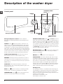
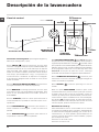
Detergent dispenser drawer: used to dispense
detergents and washing additives (see “Detergents and
laundry”).
ON/OFF button : press this briefly to switch the ma-
chine on or off. The START/PAUSE indicator light, which
flashes slowly in a green colour shows that the machine
is switched on. To switch off the washer dryer during the
wash cycle, press and hold the button for approximately 2
seconds; if the button is pressed briefly or accidentally the
machine will not switch off. If the machine is switched off
during a wash cycle, this wash cycle will be cancelled.
WASH CYCLE SELECTOR buttons: used to set the
desired wash cycle (see “Table of wash cycles”).
MEMORY button: press and hold the button to store a
cycle with your own set of preferences in the memory of
the machine. To recall a previously stored cycle, press the
MEMO button.
FUNCTION buttons: press the button to select the
desired function. The corresponding indicator light on the
display will switch on.
SPIN button : press to reduce or completely exclude
the spin cycle - the value is indicated on the display.
TEMPERATURE button : press to decrease the tem-
perature: the value will be shown on the display.
CONTROL PANEL LOCK button : to activate the control
panel lock, press and hold the button for approximately 2
seconds. When the symbol is illuminated, the control
panel is locked (apart from the ON/OFF key). This means
it is possible to prevent wash cycles from being modified
accidentally, especially where there are children in the home.
To deactivate the control panel lock, press and hold the
button for approximately 2 seconds.
DELAYED START button : press to set a delayed start
time for the selected wash cycle. The delay time will be
shown on the display.
DRYING button : press to set a drying cycle.
START/PAUSE button with indicator light: when the gre-
en indicator light flashes slowly, press the button to start a
wash cycle. Once the cycle has begun the indicator light
will remain lit in a fixed manner. To pause the wash cycle,
press the button again; the indicator light will flash in an
orange colour. If the symbol is not illuminated, the door
may be opened. To start the wash cycle from the point at
which it was interrupted, press the button again.
Standby mode
This washing machine, in compliance with new energy sa-
ving regulations, is fitted with an automatic standby system
which is enabled after about 30 minutes if no activity is
detected. Press the ON-OFF button briefly and wait for the
machine to start up again.
Consumption in off-mode: 0,5 W
Consumption in Left-on: 8 W
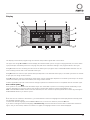
Description of the washer dryer
Control panel
TEMPERATURE
Button
WASH
CYCLE
SELECTOR
Buttons
Detergent dispenser drawer
FUNCTION
buttons
ON/OFF
button
SPIN SPEED
Button
START/PAUSE
button with indicator
light
DRYING
Button
DISPLAY
DELAYED
START
Button
MEMORY
Button
CONTROL PANEL
LOCK button

GB
9
Display
The display is useful when programming the machine and provides a great deal of information.
The upper two strings A and B are used to display the selected wash cycle or the type of drying selected, the current wash
cycle phase (the selected dryness level or drying time) and all the indications relating to the progress status of the cycle.
String C shows the time remaining until the end of the wash cycle in progress and, if a DELAYED START has been set, the
time remaining until the start of the selected wash cycle.
String D shows the maximum spin speed value (this depends on the selected wash cycle); if the wash cycle does not include
a spin cycle, the string remains unused.
String E shows the maximum temperature value which may be selected (this depends on the wash cycle used); if the tempe-
rature of the wash cycle cannot be modified, the string remains unused.
Indicator lights F correspond to the functions and light up when the selected function is compatible with the set wash cycle.
Door locked symbol
If the symbol is lit, this indicates that the washer dryer door is blocked to prevent it from being opened accidentally. To pre-
vent any damage from occurring, wait for the symbol to switch itself off before opening the appliance door.
N.B.: if the DELAYED START function has been activated, the door cannot be opened; pauses the machine by pressing the
START/PAUSE button if you wish to open it.
! The first time the machine is switched on, you will be asked to select the language and the display will automatically show
the language selection menu.
To select the desired language press the X and Y buttons; to confirm the selection press the Z button.
If you wish to change the selected language, simultaneously press and hold all the three buttons marked with an L in the
figure, until you hear a beep. Switch the machine on again; the language selection menu will be displayed.
A
B
C
D
E
F
Z
X
Y
L
F
F

10
GB
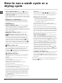
How to run a wash cycle or a
drying cycle
1. SWITCH THE MACHINE ON. Press the button; the
text WELCOME will appear on the display and the START/
PAUSE indicator light will flash slowly in a green colour.
2. LOAD THE LAUNDRY. Open the porthole door. Load the
laundry, making sure you do not exceed the maximum load
value indicated in the table of programmes on the following
page.
3. MEASURE OUT THE DETERGENT. Pull out the
detergent dispenser drawer and pour the detergent into
the relevant compartments as described in “Detergents
and laundry”.
4. CLOSE THE DOOR.
5. SELECT THE WASH CYCLE. Press one of the WASH
CYCLE SELECTOR buttons to select the required wash
cycle; the name of the wash cycle will appear on the
display. A temperature and spin speed is set for each wash
cycle; these may be adjusted. The duration of the cycle will
appear on the display.
6. CUSTOMISE THE WASH CYCLE. Use the relevant
buttons:
Modifying the temperature and/or spin
speed. The machine automatically selects the maximum
temperature and spin speed set for the selected wash
cycle; these values cannot therefore be increased. The
temperature can be decreased by pressing the button,
until the cold wash “OFF” setting is reached. The spin
speed may be progressively reduced by pressing the
button, until it is completely excluded (the “OFF” setting). If
these buttons are pressed again, the maximum values are
restored.
Setting a delayed start.
To set a delayed start for the selected programme, press
the corresponding button repeatedly until the required
delay period has been reached. When this option is
enabled, the symbol lights up on the display. To remove
the delayed start function press the button until the text
“OFF” appears on the display.
Setting the drying cycle.
The desired drying cycle type may be set by pressing the
DRYING button once or several times. Two options are
available:
A - Based on the how damp the clothes are once they
have been dried:
Iron dry: slightly damp clothes, easy to iron.
Hanger dry: dry clothes to put away.
Cupboard dry: very dry clothes, recommended for
towelling and bathrobes.
B - Based on time: from 40 minutes to 180.
To exclude the drying phase press the relevant button until
the text OFF appears on the display.
If your laundry load to be washed and dried is much greater
than the maximum stated load (see adjacent table), perform
the wash cycle, and when the cycle is complete, divide
the garments into groups and put some of them back in
the drum. At this point, follow the instructions provided
for a “Drying only” cycle. Repeat this procedure for the
remainder of the load.
N.B: a cooling-down period is always added to the end of
each drying cycle.
Drying only
Select a drying setting ( - - ) using the WASH
CYCLE selector in accordance with the type of fabric, then
select the desired drying type using the DRYING button.
Modifying the cycle settings.
• Press the button to enable the function; the indicator
light corresponding to the button will switch on.
• Press the button again to disable the function; the
indicator light will switch off.
! If the selected function is not compatible with the
programmed wash cycle, the indicator light will flash and
the function will not be activated.
! If the selected function is not compatible with another
function which has been selected previously, the indicator
light corresponding to the first function selected will flash
and only the second function will be activated; the indicator
light corresponding to the enabled function will remain lit.
! The functions may affect the recommended load value
and/or the duration of the cycle.
7. START THE PROGRAMME. Press the START/PAUSE
button. The corresponding indicator light will become
green, remaining lit in a fixed manner, and the door will be
locked (the DOOR LOCKED symbol will be on). During
the wash cycle, the name of the phase in progress will
appear on the display. To change a wash cycle while it is
in progress, pause the washer dryer using the START/
PAUSE button (the START/PAUSE indicator light will flash
slowly in an orange colour); then select the desired cycle
and press the START/PAUSE button again.
To open the door while a cycle is in progress, press the
START/PAUSE button; if the DOOR LOCKED symbol
is switched off the door may be opened. Press the START/
PAUSE button again to restart the wash cycle from the
point at which it was interrupted.
8. THE END OF THE WASH CYCLE. This will be indicated
by the text “END OF CYCLE” on the display; when the
DOOR LOCKED symbol switches off the door may be
opened. Open the door, unload the laundry and switch off
the machine.
! If you wish to cancel a cycle which has already begun, press
and hold the button. The cycle will be stopped and the
machine will switch off.

GB
11
Wash cycles and functions
Wash functions
! If the selected function is not compatible with the
programmed wash cycle, the indicator light will flash and the
function will not be activated.
! If the selected function is not compatible with another
function which has been selected previously, the indicator
light corresponding to the first function selected will flash and
only the second function will be activated; the indicator light
corresponding to the enabled function will remain lit.
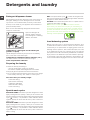
Stain removal
This function is particularly useful
for the removal of stubborn
stains.
Place extra compartment 3
(supplied). When pouring in
the bleach, be careful not to
exceed the “max” level marked
on the central pivot (see figure).
To run the bleach cycle on its
own, pour the bleach into extra
compartment 3, set the “Rinse”
programme and activate the “Stain removal” programme. To
bleach during a wash cycle, pour in the detergent and any fabric
softener you wish to use, set the desired wash cycle and enable
the “Stain removal” function.
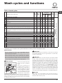
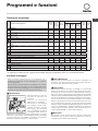
For all Test Institutes:
* Test wash cycle in compliance with regulation EN 50229: set wash cycle with a temperature of 60°C.
Table of wash cycles
Extra rinse
By selecting this option, the efficiency of the rinse is increased
and optimal detergent removal is guaranteed. It is particularly
useful for sensitive skin.
Easy iron
By selecting this function, the wash and spin cycles will be modified
in order to reduce the formation of creases. At the end of the cycle
the washer dryer will perform slow rotations of the drum; the EASY
IRON indicator light will switch on, the START/PAUSE indicator light
will flash in an orange colour and the text “END OF CYCLE” will
appear on the display. To end the cycle, press the START/PAUSE
button or the EASY IRON button. For the Silk/Curtains cycle, the
machine will end the cycle while the laundry is soaking; the EASY
IRON indicator light will switch on, the START/PAUSE indicator light
will flash in an orange colour and the text “STOP WITH WATER” will
appear on the display. To drain the water so that the laundry may be
removed, press the START/PAUSE button or the EASY IRON button.
Mini load
This function is recommended for when the load of laundry is
equal to half, or less than half, of the maximum recommended
load (see Table of wash cycles).
M
AX
1
3
2
Wash cycles
Description of the wash cycle
Max.
temp.
(°C)
Max.
speed
(rpm)
Dry-
ing
Detergents
Max.
load
(kg)
Cycle
duration
Ble-
ach
Wash
Fabric
softener
Everyday wash cycles (Daily)
The duration of the wash cycles can be checked
on the display.
White Cottons (*) (1st press of the button): extremely soiled whites. 90° 1200
7
White Cottons (2nd press of the button): heavily soiled whites and resistant
colours.
60° 1200
7
Cottons Coloured (3rd press of the button): heavily soiled whites and deli-
cate colours.
40° 1200
7
Synthetics Resistant (1st press of the button): heavily soiled resistant colours. 60° 1000
3
Synthetics Delicate (2nd press of the button): lightly soiled resistant colours. 40° 1000
3
Fastwash 30Min (1st press of the button): to refresh lightly soiled garments
quickly (not suitable for wool, silk and clothes which require washing by hand).
30° 800 - -
3
Fastwash 15Min (2nd press of the button) : to refresh lightly soiled gar-
ments quickly (not suitable for wool, silk and clothes which require washing
by hand).
30° 800 - -
1,5
Silk/Curtains: for garments in silk and viscose, lingerie. 30° 0 - -
1
M
Memory: allows for any wash cycle to be stored.
Woolmark Platinum: for wool, cashmere, etc. 40° 800
-
1,5
Drying Programmes
Cotton dry (1st press of the button):
- -
- - - 5
Synthetics dry (2nd press of the button)
- -
- - - 3
Wool dry (3rd press of the button)
- -
- - - 1,5
Partials wash cycles
Fast Spin Resistents - 1200
- - - 7
Rinse Cottons (1st press of the button): - 1200
-
7
Pump Out (2nd press of the button) - 0 - - - - 7

12
GB
Detergents and laundry
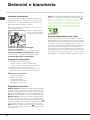
Detergent dispenser drawer
Good washing results also depend on the correct dose of
detergent: adding too much detergent will not necessa-
rily result in a more efficient wash, and may in fact cause
build up on the inside of your appliance and contribute to
environmental pollution.
! Do not use hand washing detergents because these
create too much foam.
Open the detergent di-
spenser drawer and pour
in the detergent or washing
additive, as follows.
compartment 1: Detergent for the wash cycle
(powder or liquid)
Liquid detergent should only be poured in immediately
prior to the start of the wash cycle.
compartment 2: Additives (fabric softeners, etc.)
The fabric softener should not overflow the grid.
extra compartment 3: Bleach
Preparing the laundry
•Dividethelaundryaccordingto:
- the type of fabric/the symbol on the label
- the colours: separate coloured garments from whites
•Emptyallgarmentpocketsandcheckthebuttons.
•Donotexceedthelistedvalues,whichrefertotheweight
of the laundry when dry: see “Table of wash cycles”.
How much does your laundry weigh?
1 sheet 400-500 g
1 pillow case 150-200 g
1 tablecloth 400-500 g
1 bathrobe 900-1200 g
1 towel 150-250 g
Special wash cycles
Fastwash 30Min: this wash cycle was designed to wash
lightly soiled garments quickly: it lasts just 30 minutes and
therefore saves both energy and time. By selecting this wash
cycle ( at 30°C), it is possible to wash different fabrics
together (except for wool and silk items), with a maximum
load of 3 kg.
Fastwash 15Min: this wash cycle was designed to wash
lightly soiled garments quickly: it lasts just 15 minutes and
therefore saves both energy and time. By selecting this wash
cycle ( at 30°C), it is possible to wash different fabrics
together (except for wool and silk items), with a maximum
load of 1.5 kg.
M
AX
1
3
2
Silk: use special wash cycle to wash all silk garments.
We recommend the use of special detergent which has been
designed to wash delicate clothes.
Curtains: fold curtains and place them in a pillow case or
mesh bag. Use wash cycle .
Wool: the wool wash cycle of this machine has been
approved by The Woolmark Company for the washing of
wool garments labelled as “hand wash” provided that the
products are washed according to the instructions on the
garment label and those issued by the manufacturer of this
washing machine (M1126)
Load balancing system
Before every spin cycle, to avoid excessive vibrations and
to distribute the load in a uniform manner, the drum rotates
continuously at a speed which is slightly greater than the
washing rotation speed. If, after several attempts, the load
is not balanced correctly, the machine spins at a reduced
spin speed. If the load is excessively unbalanced, the washer
dryer performs the distribution process instead of spinning.
To encourage improved load distribution and balance, we
recommend small and large garments are mixed in the load.

GB
13
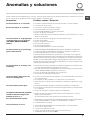
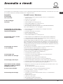
Troubleshooting
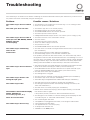
Your washer dryer could fail to work. Before contacting the Technical Assistance Centre (see “Assistance”), make sure that
the problem cannot be solved easily using the following list.
Problem:
The washer dryer does not switch
on.
The wash cycle does not start.
The washer dryer does not take in
water (the text “NO WATER, CHECK
SUPPLY” appears
on the display).
The washer dryer continuously
takes in and
drains water.
The washer dryer does not drain or
spin.
The washer dryer vibrates a lot
during the spin cycle.
The washer dryer leaks.
The machine is locked and the display
flashes, indicating an
error code (e.g. F-01, F-..).
There is too much foam.
The washer-dryer does not dry.
Possible causes / Solutions:
•Theapplianceisnotpluggedintothesocketfully,orisnotmakingcontact.
•Thereisnopowerinthehouse.
•Thewasherdryerdoorisnotclosedproperly.
•TheON/OFFbuttonhasnotbeenpressed.
•TheSTART/PAUSEbuttonhasnotbeenpressed.
•Thewatertaphasnotbeenopened.
• Adelayedstarthasbeenset(see “How to run a wash cycle or a drying cycle”).
•Thewaterinlethoseisnotconnectedtothetap.
•Thehoseisbent.
•Thewatertaphasnotbeenopened.
•Thereisnowatersupplyinthehouse.
•Thepressureistoolow.
•TheSTART/PAUSEbuttonhasnotbeenpressed.
•Thedrainhoseisnotfittedataheightbetween65and100cmfromthefloor
(see “Installation”).
•Thefreeendofthehoseisunderwater(see “Installation”).
•Thewalldrainagesystemisnotfittedwithabreatherpipe.
If the problem persists even after these checks, turn off the water tap, switch
the appliance off and contact the Assistance Service. If the dwelling is on one of
the upper floors of a building, there may be problems relating to water drainage,
causing the washer dryer to fill with water and drain continuously. Special anti-
draining valves are available in shops and help to avoid this inconvenience.
•Thewashcycledoesnotincludedraining:somewashcyclesrequirethedrain
phase to be started manually (see “Wash cycles and functions”).
•TheEASYIRONfunctionhasbeenactivated:Tocompletethewashcycle,
press the START/PAUSE button (see “Wash cycles and functions”).
•Thedrainhoseisbent(see “Installation”).
•Thedrainageductisclogged.
•Thedrumwasnotunlockedcorrectlyduringinstallation(see “Installation”).
•Thewasherdryerisnotlevel(see “Installation”).
•Thewasherdryeristrappedbetweencabinetsandwalls(see “Installation”).
•Thewaterinlethoseisnotscrewedonproperly(see “Installation”).
•Thedetergentdispenserdrawerisblocked(forcleaninginstructions,see
“Care and maintenance”).
•Thedrainhoseisnotfixedproperly(see “Installation”).
•Switchoffthemachineandunplugit,waitforapproximately1minuteand
then switch it back on again.
If the problem persists, contact the Technical Assistance Service.
•Thedetergentisnotsuitableformachinewashing(itshoulddisplaythetext
“for washer dryers” or “hand and machine wash”, or the like).
•Toomuchdetergentwasused.
• Theapplianceisnotpluggedintothesocket,ornotenoughtomakecontact.
• Therehasbeenapowerfailure.
• The appliance door is not shut properly.
• Adelayedstarthasbeenset.
• DRYINGisintheOFF position.

14
GB
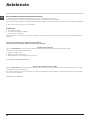
Service
Before calling for Assistance:
• Check whether you can solve the problem alone (see “Troubleshooting”);
• Restarttheprogrammetocheckwhethertheproblemhasbeensolved;
• Ifthisisnotthecase,contactanauthorisedTechnicalAssistanceCentreusingthetelephonenumberprovidedonthe
guarantee certificate.
! Always request the assistance of authorised technicians.
Have the following information to hand:
• thetypeofproblem;
• theappliancemodel(Mod.);
• theserialnumber(S/N).
This information can be found on the data plate applied to the rear of the washer dryer, and can also be found on the
front of the appliance by opening the door.

FR
15
Français
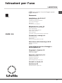
Sommaire
Installation, 16-17-18-19
Déballage et mise à niveau
Raccordements eau et électricité
Premier cycle de lavage
Caractéristiques techniques
Instructions pour l’installateur
Entretien et soin, 20
Coupure de l’arrivée d’eau et du courant
Nettoyage du lavante-séchante
Nettoyage du tiroir à produits lessiviels.
Entretien du hublot et du tambour
Nettoyage de la pompe
Contrôle du tuyau d’arrivée de l’eau
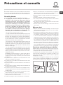
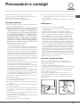
Précautions et conseils, 21
Sécurité générale
Mise au rebut
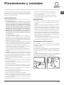
Ouverture manuelle de la porte hublot
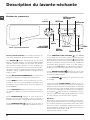
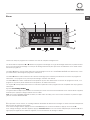
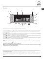
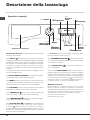
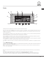
Description du lavante-séchante, 22-23
Bandeau de commandes
Écran
Comment effectuer un cycle de lavage
ou un séchage, 24
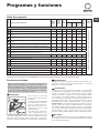
Programmes et fonctions, 25
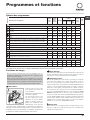
Tableau des programmes
Fonctions de lavage
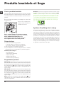
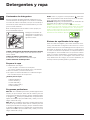
Produits lessiviels et linge, 26
Tiroir à produits lessiviels
Triage du linge
Programmes spéciaux
Système d’équilibrage de la charge
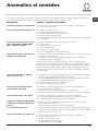
Anomalies et remèdes, 27
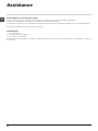
Assistance, 28
FR
SWDD 129
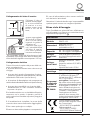
Mode d’emploi
LAVANTE-SÉCHANTE
! Ce symbole vous rappelle de lire ce
mode d’emploi.

16
FR
Installation
! Conserver ce mode d’emploi pour pouvoir le con-
sulter à tout moment. En cas de vente, de cession ou
de déménagement, veiller à ce qu’il suive toujours le
lavante-séchante pour que son nouveau propriétaire
soit informé sur son mode de fonctionnement et
puisse profiter des conseils correspondants.
! Lire attentivement les instructions: elles fournis-
sent des conseils importants sur l’installation,
l’utilisation et la sécurité de l’appareil.
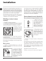
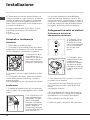
Déballage et mise à niveau
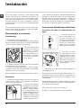
Déballage
1. Déballer le lavante-séchante.
2. Contrôler que le lavante-séchante n’a pas été
endommagé pendant le transport. S’il est abîmé,
ne pas le raccorder et contacter le vendeur.
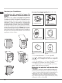
3. Enlever les 4 vis
de protection servant
au transport, le ca-
outchouc et la cale,
placés dans la partie
arrière (voir figure).
4. Boucher les trous à l’aide des bouchons
plastique fournis.
5. Conserver toutes ces pièces: il faudra les re-
monter en cas de transport du lavante-séchante.
! Les pièces d’emballage ne sont pas des jouets
pour enfants.
Mise à niveau
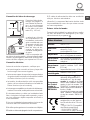
1. Installer le lavante-séchante sur un sol plat
et rigide, sans l’appuyer contre des murs, des
meubles ou autre.
2. Si le sol n’est pas
parfaitement horizon-
tal, visser ou dévisser
les pieds de réglage
avant (voir figure) pour
niveler l’appareil; son
angle d’inclinaison,
mesuré sur le plan
de travail, ne doit pas
dépasser 2°.
Une bonne mise à niveau garantit la stabilité
de l’appareil et évite qu’il y ait des vibrations,
du bruit et des déplacements en cours de
fonctionnement. Si la machine est posée sur
de la moquette ou un tapis, régler les pieds de
manière à ce qu’il y ait suffisamment d’espace
pour assurer une bonne ventilation.
Raccordements eau et électricité
Raccordement du tuyau d’arrivée de l’eau
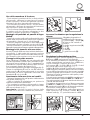
1. Reliez le tuyau d’ali-
mentation en le vissant
à un robinet d’eau froi-
de à embout fileté 3/4
gaz (voir figure).
Faire couler l’eau ju-
squ’à ce qu’elle soit
limpide et sans impure-
tés avant de raccorder.
2. Raccorder le tuyau
d’arrivée de l’eau au
lavante-séchante en le
vissant à la prise d’eau
prévue, dans la partie
arrière en haut à droite
(voir figure).
3. Attention à ce que le tuyau ne soit pas plié
ou écrasé.
! La pression de l’eau doit être comprise entre
les valeurs indiquées dans le tableau des Ca-
ractéristiques techniques (voir page ci-contre).
! Si la longueur du tuyau d’alimentation ne suffit
pas, s’adresser à un magasin spécialisé ou à un
technicien agréé.
! N’utiliser que des tuyaux neufs.
! Utiliser ceux qui sont fournis avec l’appareil.

FR
17
65 - 100 cm
Raccordement du tuyau de vidange
Raccorder le tuyau
d’évacuation, sans
le plier, à un conduit
d’évacuation ou à une
évacuation murale pla-
cés à une distance du
sol comprise entre 65
et 100 cm;
ou bien l’accrocher à
un évier ou à une bai-
gnoire, dans ce cas,
fixer le support en pla-
stique fourni avec l’ap-
pareil au robinet (voir
figure). L’extrémité libre
du tuyau d’évacuation
ne doit pas être plon-
gée dans l’eau.
! L’utilisation d’un tuyau de rallonge est abso-
lument déconseillée mais si on ne peut faire
autrement, il faut absolument qu’il ait le même
diamètre que le tuyau original et sa longueur ne
doit pas dépasser 150 cm.
Branchement électrique
Avant de brancher la fiche dans la prise de cou-
rant, s’assurer que:
•lapriseestbienreliéeàlaterreetestconforme
aux réglementations en vigueur;
•lapriseestbienapteàsupporterlapuissance
maximale de l’appareil indiquée dans le tableau
des Caractéristiques techniques (voir ci-contre);
•la tension d’alimentationestbien comprise
entre les valeurs figurant dans le tableau des
Caractéristiques techniques (voir ci-contre);
•lapriseestbiencompatibleaveclafichedu
lavante-séchante. Autrement, remplacer la
prise ou la fiche.
! Le lavante-séchante ne doit pas être installé
dehors, même à l’abri, car il est très dangereux
de le laisser exposé à la pluie et aux orages.
! Après installation du lavante-séchante, la prise
de courant doit être facilement accessible.
! N’utiliser ni rallonges ni prises multiples.
! Le câble ne doit être ni plié ni trop écrasé.
! Le câble d’alimentation ne doit être remplacé
que par des techniciens agréés.
Attention! Nous déclinons toute responsabilité en cas
de non-respect des normes énumérées ci-dessus.
Premier cycle de lavage
Avant la première mise en service de l’appareil, ef-
fectuer un cycle de lavage avec un produit lessiviel
mais sans linge et sélectionner le programme .
Caractéristiques techniques
Modèle
SWDD 129
Dimensions
largeur 59,5 cm
hauteur 81,5 m
profondeur 54,5 cm
Capacité
de 1 à 7 kg pour le lavage
de 1 à 5 kg pour le séchage
Raccordements
électriques
Voir la plaque signalétique appliquée
sur la machine
Raccordements
hydrauliques
pression maximale 1 MPa (10 bar)
pression minimale 0,05 MPa (0,5
bar) capacité du tambour 52 litres
Vitesse d’esso-
rage
jusqu’à 1200 tours minute
Programmes de
contrôle selon
la règlements
EN 50229
avage: programme (1° pression
de la touche); température 60°C;
effectué avec une charge de 7 kg.
séchage: pour le séchage de la
charge de linge réduite, sélectionner
le niveau de séchage «A REPAS-
SER», le linge doit comprendre: 2
draps, 1 taie d’oreiller et 1 serviette
de toilette;
pour le séchage de la charge de
linge restante, sélectionner le niveau
de séchage «A RANGER».
Cet appareil est conforme aux Directi-
ves Communautaires suivantes:
- 2004/108/CE (Compatibilité élec-
tromagnétique)
- 2006/95/CE (Basse Tension)
- 2012/19/EU - WEEE

18
FR
Instructions pour l’installateur
Application du panneau d’habillage en
bois sur la porte et montage du machine
à laver à l’intérieur des éléments:
Au cas où, après le montage du panneau en bois,
il faudrait expédier la machine pour son installation
finale, nous vous conseillons de la laisser dans
son emballage d’origine. L’emballage a été juste-
ment réalisé de manière à permettre le montage
du panneau en bois sur la machine sans déballer
complètement le produit (voir figures ci-dessous).
Le panneau en bois couvrant la façade ne doit
pas avoir plus de 13 mm d’épaisseur, il peut être
articulé tant à droite qu’à gauche. Pour plus de
facilité d’emploi, nous conseillons d’adopter le
même sens d’ouverture que pour le hublot dont
les charnières sont montées sur le côté gauche.
A
B
C
D
E
Tur seite
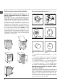
Accessoires montage porte (Fig.1-2-3-4-5).
Fig. 1
N°2 Charnière
N°1 Aimant N°1 Butoir aimant
N°1 Cheville en
caoutchouc
N°2 Supports charnière
N°4 Cales
Fig. 2
Fig. 3 Fig. 4
Fig. 5
Fig. 4/B
- 6 vis autotaraudeuses l = 13 mm “type A”.
- 2 vis métriques à tête évasée l = 25 mm “type
B”; pour fixation du butoir aimant au meuble.
- 4 vis métriques l = 15 mm “type C”; pour
montage des supports charnière au meuble.
- 4 vis métriques l = 7 mm “type D”; pour mon-
tage des charnières aux supports.
Montage des pièces sur la façade de la
machine.
- Montez les supports de la charnière sur la faça-
de, en positionnant le trou indiqué par une flèche
dans la fig. 1 vers l’intérieur de la façade et inter-
posez une cale (fig. 4/B). Utilisez les vis type C.
- Montez le butoir aimant du côté opposé en
haut et interposez deux cales (fig. 4/B). Utilisez
les deux vis type B.

FR
19
Utilisation du gabarit de forage.
- Pour marquer l’emplacement des trous sur le
côté du panneau, alignez le gabarit de perçage
avec le côté supérieur gauche du panneau en vous
servant des lignes tracées aux extrémités.
- Pour marquer l’emplacement des trous sur le
côté droit du panneau, alignez le gabarit de perça-
ge avec le côté supérieur droit du panneau.
- Réalisez à l’aide d’une fraise appropriée les quatre
emplace-ments où devront trouver place les deux
charnières, la cheville en caoutchouc et l’aimant.
Montage des pièces sur le panneau en
bois (Porte).
- Montez les charnières aux emplacements prévus (la
partie mobile de la charnière doit se trouver vers l’ex-
térieur du panneau) et fixez-les à l’aide de 4 vis type A.
- Montez l’aimant à son emplacement en haut,
à l’opposé des charnières et fixez-le au moyen
de deux vis type B.
- Montez la cheville en caoutchouc à sa place en bas.
Le panneau est à présent prêt, vous pouvez le
monter sur la machine.
Montage du panneau sur la machine.
Introduisez l’ergot de la charnière indiqué par la
flèche fig. 2 dans le logement du support charnière,
poussez le panneau vers la façade de la machine et
fixez les deux charnières à l’aide des deux vis type D.
Fixation du support de la base.
Si la machine est installée à une extrémité de la
cuisine intégrée, montez une ou les deux glissières
du socle comme illustré fig. 8 en réglant leur pro-
fondeur en fonction de la position du socle et, au
besoin, fixez-le à ces dernières fig. 9. Pour monter
le support de la base, procédez comme suit (fig.
8): Fixez l’équerre P à l’aide de la vis R, insérez le
support de la base Q dans la fente prévue et après
l’avoir dûment positionné bloquez-le à l’aide de
l’équerre d’assemblage P et de la vis R.
Montage de la machine à l’intérieur des
éléments.
- Poussez la machine à travers l’ouverture en
l’alignant aux autres meubles (fig. 6).
- Servez-vous des pieds de réglage pour amener
la machine à la hauteur désirée.
- Pour régler la position du panneau en bois à la
verticale et à l’horizontale, servez-vous des vis C et
D comme illustré fig. 7.
Important: fermez la partie inférieure de la faça-
de, la base touchant au sol.
Fig. 8 Fig. 9
Accessoires fournis pour le réglage de la
hauteur.
Vous trouverez à l’intérieur du couvercle en polysty-
rène (fig. 10): 2 traverses (G); 1 listel (M);
et à l’intérieur du tambour :
4 pieds supplémentaires
(H),
4 vis (I),
4 vis (R),
4 écrous (L),
2 supports pour la base (Q)
Réglage de la machine en hauteur.
La machine peut être réglée en hauteur (de 815
mm à 835 mm) à l’aide de ses 4 pieds.
Si vous souhaitez l’amener à une hauteur supé-
rieure à celle qui est indiquée plus haut, c’est à dire
jusqu’à 870 mm, utilisez les accessoires suivants :
les 2 traverses (G); les 4 pieds (H); les 4 vis (I); les
4 écrous (L) puis procédez comme suit (fig. 11):
démontez les 4 pieds originaux, positionnez une
traverse G dans la partie avant de la machine,
fixez-la à l’aide des vis I (en les vissant dans les
trous où étaient fixés les pieds originaux) puis
montez les nouveaux pieds H.
Procédez de même dans la partie arrière de la
machine.
Vous pouvez alors régler les pieds H pour élever
ou abaisser la machine de 835 mm à 870 mm.
Après avoir atteint la hauteur désirée, bloquez les
écrous L à la traverse G.
Pour régler la machine à une hauteur comprise
entre 870 mm et 900 mm, montez le listel M et
réglez les pieds H jusqu’à la hauteur souhaitée.
Pour monter le listel, procédez comme suit:
desserrez les trois vis N situées dans la partie avant
du couvercle, montez le listel M comme illustré
fig. 12 et serrez les vis N.
D
C
C
570
min
815
540
595
820 ÷ 900
600 min
Fig. 6 Fig. 7
L
I
H
G
M
Fig. 11 Fig. 12
Fig. 10

20
FR
Entretien et soin
Coupure de l’arrivée d’eau et du
courant
•Fermerlerobinetdel’eauaprèschaquelavage.
Cela réduit l’usure de l’installation hydraulique
du lavante-séchante et évite tout danger de
fuites.
•Débrancher la fiche de la prise de courant
lors de tout nettoyage du lavante-séchante et
pendant tous les travaux d’entretien.
Nettoyage du lavante-séchante
Pour nettoyer l’extérieur et les parties en caout-
chouc, utiliser un chiffon imbibé d’eau tiède et
de savon. N’utiliser ni solvants ni abrasifs.
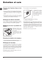
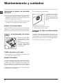
Nettoyage du tiroir à produits les-
siviels.
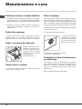
Soulever le tiroir et le
tirer vers soi pour le
sortir de son logement
(voir figure).
Le laver à l’eau cou-
rante; effectuer cette
opération assez sou-
vent.
Entretien du hublot et du tambour
•Ilfauttoujourslaisserlehublotentrouvertpour
éviter la formation de mauvaise odeurs.
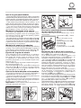
Nettoyage de la pompe
Le lavante-séchante est équipé d’une pompe
autonettoyante qui n’exige aucune opération
d’entretien. Il peut toutefois arriver que de menus
objets (pièces de monnaie, boutons) tombent
dans la préchambre qui protège la pompe, pla-
cée en bas de cette dernière.
! S’assurer que le cycle de lavage est bien ter-
miné et débrancher la fiche.
1
2
Pour accéder à cette préchambre:
1. dévisser le cou-
vercle en le tournant
dans le sens inverse
des aiguilles d’une
montre (voir figure): il
est normal qu’un peu
d’eau s’écoule;
2. nettoyer soigneusement l’intérieur;
3. revisser le couvercle;
Contrôle du tuyau d’arrivée de l’eau
Contrôler le tuyau d’alimentation au moins une
fois par an. Procéder à son remplacement en cas
de craquèlements et de fissures: car les fortes
pressions subies pendant le lavage pourraient
provoquer des cassures.
! N’utiliser que des tuyaux neufs.
La page est en cours de chargement...
La page est en cours de chargement...
La page est en cours de chargement...
La page est en cours de chargement...
La page est en cours de chargement...
La page est en cours de chargement...
La page est en cours de chargement...
La page est en cours de chargement...
La page est en cours de chargement...
La page est en cours de chargement...
La page est en cours de chargement...
La page est en cours de chargement...
La page est en cours de chargement...
La page est en cours de chargement...
La page est en cours de chargement...
La page est en cours de chargement...
La page est en cours de chargement...
La page est en cours de chargement...
La page est en cours de chargement...
La page est en cours de chargement...
La page est en cours de chargement...
La page est en cours de chargement...
La page est en cours de chargement...
La page est en cours de chargement...
La page est en cours de chargement...
La page est en cours de chargement...
La page est en cours de chargement...
La page est en cours de chargement...
La page est en cours de chargement...
La page est en cours de chargement...
La page est en cours de chargement...
La page est en cours de chargement...
La page est en cours de chargement...
La page est en cours de chargement...
La page est en cours de chargement...
La page est en cours de chargement...
-
 1
1
-
 2
2
-
 3
3
-
 4
4
-
 5
5
-
 6
6
-
 7
7
-
 8
8
-
 9
9
-
 10
10
-
 11
11
-
 12
12
-
 13
13
-
 14
14
-
 15
15
-
 16
16
-
 17
17
-
 18
18
-
 19
19
-
 20
20
-
 21
21
-
 22
22
-
 23
23
-
 24
24
-
 25
25
-
 26
26
-
 27
27
-
 28
28
-
 29
29
-
 30
30
-
 31
31
-
 32
32
-
 33
33
-
 34
34
-
 35
35
-
 36
36
-
 37
37
-
 38
38
-
 39
39
-
 40
40
-
 41
41
-
 42
42
-
 43
43
-
 44
44
-
 45
45
-
 46
46
-
 47
47
-
 48
48
-
 49
49
-
 50
50
-
 51
51
-
 52
52
-
 53
53
-
 54
54
-
 55
55
-
 56
56


Indesit SWDD 129 EU Mode d'emploi
- Catégorie
- Sèche-linge
- Taper
- Mode d'emploi
Documents connexes
-
Scholtes sdle 129 eu full Le manuel du propriétaire
-
Ariston BHWD 125 GCC Le manuel du propriétaire
-
-
-
Indesit IWDE 127 EU Mode d'emploi
-
-
-
-
Indesit SMLE 129 (EU) Le manuel du propriétaire
Autres documents
-
-
-
Scholtes SMLE 129 Instructions For Use Manual
-
Whirlpool SMLE 129 (EU) Mode d'emploi
-
HOTPOINT/ARISTON CAWD 129 (EU) Mode d'emploi
-
-
-
HOTPOINT/ARISTON CHWD 129 EU Mode d'emploi
-
-