Audio Design LA-1000MD Le manuel du propriétaire
- Catégorie
- Amplificateurs audio de voiture
- Taper
- Le manuel du propriétaire

M
ono
• LA-600M
• LA-1000MD
• LA-2000MD
• LA-3000MD
A
mplifiers
La page est en cours de chargement...

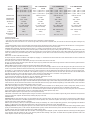
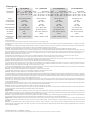
Model
LA-600M LA-1000MD LA-2000MD LA-3000MD
Power
Rating
MAX
400 x 1 @ 4Ω
600 x 1 @ 2Ω
RMS
200 x 1 @ 4Ω
300 x 1 @ 2Ω
MAX
500 x 1 @ 4Ω
750 x 1 @ 2Ω
1000 x 1 @ 1Ω
RMS
250 x 1 @ 4Ω
375 x 1 @ 2Ω
500 x 1 @ 1Ω
MAX
1000 x 1 @ 4Ω
1500 x 1 @ 2Ω
2000 x 1 @ 1Ω
RMS
400 x 1 @ 4Ω
700 x 1 @ 2Ω
1000 x 1 @ 1Ω
MAX
1500 x 1 @ 4Ω
2250 x 1 @ 2Ω
3000 x 1 @ 1Ω
RMS
600 x 1 @ 4Ω
1000 x 1 @ 2Ω
1400 x 1 @ 1Ω
Crossover
12dB/Oct HP/FULL/LPBP 12dB/Oct Low Pass 12dB/Oct Low Pass 12dB/Oct Low Pass
Crossover
Frequency
Variable
40Hz - 150Hz
Variable
35Hz - 250Hz
Variable
35Hz - 250Hz
Variable
35Hz - 250Hz
Subsonic
Filter
Variable
15Hz - 55Hz
Variable
15Hz - 55Hz
Variable
15Hz - 55Hz
Variable
15Hz - 55Hz
Bass Boost
0 to +12dB @ 45Hz
(Remote Included)
0 to +18dB @ 45Hz
(Remote Included)
0 to +18dB @ 45Hz
(Remote Included)
0 to +18dB @ 45Hz
(Remote Included)
Inputs
RCA RCA / Balanced Input RCA / Balanced Input RCA / Balanced Input
Fuse(s)
25A(2) 30A(2) 50A(2) 70A(2)
Dimensions
(LxWxH)
9.8” x 9.4” x 2.3” 11” x 9.4” x 2.3” 13.8” x 9.4” x 2.3” 15” x 9.4” x 2.3”
Installation
Preliminary Considerations:
• If you feel unsure about installing this system yourself, have it installed by a qualified technician.
• Think before you drill! Be careful not to cut or drill into gas tanks, fuel lines, brake or hydraulic lines, vacuum lines or electrical wiring when working on any
vehicle.
• Aftermarket amplifiers will put an increased load on the vehicle’s battery and charging system, which can reduce battery and alternator life. It is strongly recom-
mended to upgrade your factory alternator and battery for optimum performance from your new audio system.
CAUTION: Before installation, disconnect the battery negative (-) terminal to prevent damage to the unit, fire and/or possible injury.
1. Choose a mounting location that will be secure and offer plenty of unobstructed space for proper cooling. Then plan the wire routing. Keep RCA cables close
together but isolated from the amplifier’s power cables and any high power auto accessories, especially electric motors. When feeding the wires through the fire
wall or any metal barrier, protect them with plastic or rubber grommets to prevent short circuits. Leave the wires long at this point to adjust for a precise fit at
a later time.
NOTE: Never run wires underneath the vehicle.
2. Prepare the power cable for attachment to the amplifier by stripping 1/2” of insulation from the end of the wire. Insert the bared wire into the B+ terminal and
tighten the setscrew to secure the cable in place.
3. Trim the power cable within 18” of the battery and strip1/2”of insulation from the end of the wire.
4. Strip 1/2” from the battery end of the power cable and crimp a large ring terminal to the cable. Use the ring terminal to connect to the battery positive terminal.
DO NOT install the fuse at this time.
NOTE: ALWAYS protect the battery and electrical system from damage with proper fusing.
5. Prepare the chassis ground by scraping any paint from the metal surface and thoroughly clean the area of all dirt and grease. Strip the end of the wire and
attach a ring connector. Fasten the cable to the chassis using a non-anodized screw and a star washer. Prepare the grounding cable for attachment to the amplifier
by stripping 1/2” of insulation from the other end of the wire. Insert the bared wire into the GND terminal and tighten the setscrew to secure the cable in place.
6. Prepare the REM turn-on wire for connection to the amplifier by stripping 1/2” of insulation from the wire end. Insert the bared wire into the REM terminal
and tighten the setscrew to secure the cable into place. Connect the other end of the REM wire to a switched 12-volt positive source.
NOTE: The switched voltage is usually taken from the source unit’s accessory/remote lead.
7. Securely mount the amplifier to the vehicle or amp rack. Remember: Think before you drill!
NOTE: Be careful not to mount the amplifier on cardboard or plastic panels.
8. Connect the source signal to the amplifier by plugging the RCA cables/high level inputs into the input jacks at the amplifier. Use only one input configuration.
Using both the RCA and High Level inputs will cause undesirable operation. When using a Master/Slave configuration (MD models only), select which amplifier
will be the master, then set the mode switch to Master and connect RCA cables to the input jacks. The Slave amplifier(s); set the mode switch to Slave and connect
RCA cables to the Slave in/out jacks from the Master’s Slave in/out jacks.
NOTE: When using High Level Inputs, if audible engine noise is present, connect the Black wire to chassis ground. If noise is still present, contact your local
authorized dealer or Lightning Audio customer service. When using a Master/Slave setup do not exceed more than two amplifiers. (MD models only)
9. Connect the speakers. Strip the speaker wires 1/2” and insert into the speaker terminal and tighten the setscrew to secure into place. Be sure to maintain
proper speaker polarity. DO NOT chassis ground any of the speaker leads as unstable operation may result.
NOTE: Mono amplifier speaker outputs (A & B) are wired in parallel internally.
10. Perform a final check of the completed system wiring to ensure that all connections are accurate. Check all power and ground connections for frayed wires
and loose connections. Complete the installation by installing the proper value fuse.
Operation
Adjusting Level: To adjust the level setting, turn the amplifier gain level to the lowest setting. Turn the source unit volume up until distortion is audible and then
slowly down until the distortion is inaudible (approximately ¾ volume position). Next, increase the amplifier level setting until once again distortion is audible
and then down slowly until the distortion is inaudible.
NOTE: Proper level setting is done by a trained professional utilizing an oscilloscope. For a more in depth setting procedure, contact Lightning Audio Technical
Support. In a Master/Slave setup ONLY adjustments made to the master amplifier will effect the output. (MD models only)
Adjusting Crossover: Select the appropriate position for the crossover filter switch. Turn the crossover adjustment knob to the lowest setting. With the system
playing at normal listening level, turn the crossover adjustment knob up slowly until the desired crossover point is achieved. Example: subwoofers- low pass with
an 80Hz crossover point and full-range- high pass with a 100Hz crossover point
NOTE: Some models include a subsonic filter with a variable 15-40Hz high pass filter designed to prevent frequencies below the audio range from being applied
to the subwoofer from the amplifier. Set this to your personal preference while listening to the system. In a Master/Slave setup ONLY adjustments made to the
master amplifier will effect the output. (MD models only)
La page est en cours de chargement...
La page est en cours de chargement...

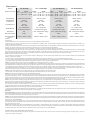
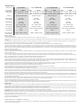
Modelo
LA-600M LA-1000MD LA-2000MD LA-3000MD
Potencia
Eléctrica
Nominal
Max.
400 x 1 @ 4Ω
600 x 1 @ 2Ω
RMS
200 x 1 @ 4Ω
300 x 1 @ 2Ω
Max.
500 x 1 @ 4Ω
750 x 1 @ 2Ω
1000 x 1 @ 1Ω
RMS
250 x 1 @ 4Ω
375 x 1 @ 2Ω
500 x 1 @ 1Ω
Max.
1000 x 1 @ 4Ω
1500 x 1 @ 2Ω
2000 x 1 @ 1Ω
RMS
400 x 1 @ 4Ω
700 x 1 @ 2Ω
1000 x 1 @ 1Ω
Max.
1500 x 1 @ 4Ω
2250 x 1 @ 2Ω
3000 x 1 @ 1Ω
RMS
600 x 1 @ 4Ω
1000 x 1 @ 2Ω
1400 x 1 @ 1Ω
Cruce
12dB/Oct HP/FULL/LPBP 12dB/Oct Pasa bajos 12dB/Oct Pasa bajos 12dB/Oct Pasa bajos
Frecuencia
de cruce
Variable
40Hz - 150Hz
Variable
35Hz - 250Hz
Variable
35Hz - 250Hz
Variable
35Hz - 250Hz
Subsónico
Variable
15Hz - 55Hz
Variable
15Hz - 55Hz
Variable
15Hz - 55Hz
Variable
15Hz - 55Hz
Refuerzo
de bajos
0 to +12dB @ 45Hz
(Se incluye el remoto)
0 to +18dB @ 45Hz
(Se incluye el remoto)
0 to +18dB @ 45Hz
(Se incluye el remoto)
0 to +18dB @ 45Hz
(Se incluye el remoto)
Entradas
RCA RCA / Entradas equilibradas RCA / Entradas equilibradas RCA / Entradas equilibradas
Fusibles
25A(2) 30A(2) 50A(2) 70A(2)
Dimensiones
(LxAxAlto)
249mm x 238mm x 58mm 280mm x 238mm x 58mm 350mm x 238mm x 58mm 520mm x 238mm x 58mm
Español
Instalación
Consideraciones preliminares:
• Si no está seguro si debe hacer la instalación de este sistema usted mismo, haga que lo instale un técnico calificado.
• ¡Piense siempre antes de perforar! Tenga cuidado de no cortar ni perforar tanques de combustible, tuberías de combustible, frenos o hidráulicas, tuberías de vacío o cableado eléctrico al trabajar en
un vehículo.
• Los amplificadores de terceros impondrán una carga mayor en la batería del vehículo y en el sistema de carga, lo que puede reducir la duración de la batería y del alternador. Se recomienda enfática-
mente que actualice su alternador y la batería de fábrica para que su sistema nuevo de sonido tenga un rendimiento óptimo.
PRECAUCIÓN: Antes de efectuar la instalación, desconecte el terminal negativo (-) de la batería para evitar daños a la unidad, incendio y/o posiblemente lesiones.
1. Escoja un lugar de montaje que sea seguro y que ofrezca abundante espacio sin obstrucciones para tener un enfriamiento correcto. Luego planee el tendido de los cables. Mantenga juntos los
cables RCA pero aislados de los cables de alimentación del amplificador y de cualquier cable de alta potencia de accesorios eléctricos del automóvil, especialmente de motores eléctricos. Al pasar los
cables a través de la mampara cortafuegos o cualquier barrera metálica, protéjalos con arandelas de plástico o caucho para evitar cortos circuitos. Deje los alambres largos en este punto, para poder
ajustarlos con exactitud más adelante.
NOTA: Nunca tienda cables abajo del vehículo.
2. Prepare el cable de alimentación para conectarlo al amplificador pelando 1/2 pulg. de aislamiento del extremo del cable. Inserte el cable desnudo en el terminal B+ y apriete el tornillo de fijación
para fijar el cable en su sitio.
3. Pele 1/2 pulgada del otro extremo del cable de alimentación del amplificador e inserte en un fusible maestro, que se debe instalar dentro de una distancia de 18 pulgadas de la batería.
4. Corte un trozo de 18 pulgadas de largo de cable de alimentación y pele 1/2 pulgada de ambos extremos. Instale a presión un terminal de anillo grande en un extremo del cable y fíjelo en el terminal
positivo (+) de la batería. Conecte el otro extremo al porta fusible maestro. NO instale el fusible en este momento.
NOTA: Proteja SIEMPRE la batería y el sistema eléctrico contra daños usando los fusibles correspondientes.
5. Prepare la tierra del chasis raspando la pintura de la superficie de metal y limpie completamente el área para evitar suciedad y grasa. Pele el extremo del cable e instale un anillo conector. Fije
el cable al chasis por medio de un tornillo no anodizado y una arandela de estrella. Prepare el cable de puesta a tierra para conectarlo al amplificador pelando 1/2 pulg. de aislamiento del otro
extremo del cable. Inserte el cable pelado en el terminal GND y apriete el tornillo de fijación para fijar el cable en su sitio.
6. Prepare el cable de encendido remoto REM para fijarlo al amplificador pelando 1/2 pulg. de aislamiento del extremo del cable. Inserte el cable pelado en el terminal REM y apriete el tornillo de
fijación para fijar el cable en su sitio. Conecte el otro extremo del cable REM a una fuente de alimentación conmutada positiva de 12 voltios.
NOTA: El voltaje conmutado normalmente se toma del cable de accesorios/remoto de la unidad fuente.
7. Monte el amplificador de manera segura en el vehículo o en un bastidor de amplificador. Recuerde: ¡Piense siempre antes de perforar!
NOTA: Tenga cuidado de no montar el amplificador sobre paneles de cartón o de plástico.
8. Conecte la señal de fuente al amplificador enchufando los cables RCA/entradas de alto nivel en los conectores de entrada en el amplificador. Use sólo la configuración de una entrada. Usar ambas
entradas, la RCA y la de alto nivel hará que la unidad funcione de manera indeseable. Al usar una configuración de maestro/esclavo (sólo en los modelos MD), seleccione cual amplificador será el
maestro, luego configure el interruptor de modo y conecte los cables RCA a los conectores de entrada. Los amplificadores esclavos; configure el interruptor de modo en esclavo y conecte los cables
RCA a los conectores de entrada/salida del esclavo desde los conectores de entrada y salida de esclavo del maestro.
NOTA: Al usar entradas de alto nivel, si se puede escuchar un ruido del motor, conecte de nuevo el cable negro a la tierra del chasis. Si el ruido sigue presente, comuníquese con su distribuidor local
autorizado o con servicio al cliente de Lightning Audio. Al usar una configuración de maestro/esclavo use sólo un (1) amplificador maestro y un (1) amplificador esclavo. NO agregue amplificadores
esclavos adicionales. (Sólo modelos MD)
9. Conecte los altavoces. Pele 1/2 pulg. los cables del altavoz e inserte en el terminal del altavoz y apriete el tornillo prisionero para fijar en su sitio. Asegúrese de mantener la polaridad correcta de
los altavoces. NO conecte a tierra ninguno de los conductores de los altavoces pues se podría causar un funcionamiento inestable.
NOTA: Las salidas monoaurales del altavoz (A y B) están cableadas en paralelo internamente.
10. Haga una comprobación final del cableado del sistema terminado para asegurar que todas las conexiones estén bien hechas. Compruebe todas las conexiones de alimentación y puesta a tierra para
determinar si hay cables deshilachados y conexiones sueltas. Complete la instalación instalando el fusible del valor correcto.
Operación
Ajuste del nivel: Para ajustar el nivel, gire los niveles de ganancia del amplificador totalmente hacia el ajuste más bajo. Suba el volumen de la unidad de fuente hasta que la distorsión sea audible
y luego comience a bajar lentamente hasta que la distorsión sea inaudible (posición aproximada de 3/4 del volumen). A continuación, suba nuevamente el ajuste del nivel del amplificador hasta que
nuevamente pueda escuchar la distorsión y luego gire hacia abajo lentamente hasta que no se pueda escuchar la distorsión.
NOTA: El ajuste correcto del nivel lo hace un profesional capacitado utilizando un osciloscopio. Por un procedimiento de ajuste más a fondo, comuníquese con el apoyo técnico de Lightning Audio. En
una configuración de maestro/esclavo SOLO los ajustes efectuados al amplificador maestro afectarán la salida. (Sólo modelos MD)
Ajuste del cruce: Seleccione la posición adecuada para el interruptor del filtro de cruce. Gire la perilla de ajuste de cruce al ajuste más bajo. Con el sistema reproduciendo al nivel normal de audición,
gire lentamente la perilla de ajuste de la frecuencia de cruce hacia arriba hasta que se logre el punto de cruce deseado. Ejemplo: Soobwoofers – pasabajos con un unto de cruce de 80Hz y pasa
altos de gama completa con un punto de cruce de 100Hz.
NOTA: Algunos modelos incluyen un filtro subsónico con un filtro pasa altos variable de 15 a 40Hz diseñado para evitar que se aplique frecuencias menores que la gama de audio desde el ampli-
ficador al subwoofer. Ajuste esto de acuerdo a su preferencia personal mientras escucha al sistema. En una configuración de maestro/esclavo SOLO los ajustes efectuados al amplificador maestro
afectarán la salida. (Sólo modelos MD)
Información de la garantía limitada
Los productos comprados por consumidores de un distribuidor autorizado de Lightning Audio situado afuera de los EE.UU. están cubiertos por el distribuidor autorizado de Lightning Audio para el
país en que se ha comprado los productos.
La page est en cours de chargement...

L
imited
W
arranty
I
nformation
Lightning Audio offers a limited warranty on products subject to the following terms:
• Length of warranty:
Speakers - One year replacement warranty from date of original purchase - requires proof of purchase.
Amplifiers - One year replacement warranty from date of original purchase - requires proof of purchase.
• What is covered:
This warranty applies only to Lightning Audio products sold to consumers by an authorized Lightning Audio Dealer in the United States
of America. Products purchased by consumers from an authorized Lightning Audio Dealer located outside of the USA are covered by
the authorized Lightning Audio Distributor for the country in which the products were purchased.
• Who is covered:
This warranty covers only the original purchaser of Lightning Audio product purchased from an authorized Lightning Audio Dealer
in the United States. In order to receive service, the purchaser must provide Lightning Audio with a dated copy of the sales receipt
stating the customer name, dealer name and product(s) purchased. Products found to be defective during the warranty period will be
replaced (with a product deemed to be equivalent at Lightning Audio’s sole discretion) by Lightning Audio.
• What is not covered:
1. Damage caused by accident, misuse, abuse, improper installation or operation, water or moisture, excessive heat, theft, or ship-
ping
2. Any cost or expense related to the removal or reinstallation of product
3. Items previously repaired, serviced or modified by an unauthorized service center
4. Any product which has had the serial number defaced, altered, or removed
5. Subsequent damage to other components
6. Any product purchased outside the U.S.
7. Any product not purchased from an authorized Lightning Audio Dealer
• Limit on implied warranties
Any implied warranties of fitness for use and merchantability are limited in duration to the period of the express warranty set forth
above. Some states do not allow limitations on the length of an implied warranty, so this limitation may not apply. No person is autho-
rized to assume for Lightning Audio any other liability in connection with the sale of the product.
• How to obtain service
Defective products should be returned to your local authorized Lightning Audio Dealer for warranty service or, you may call 1-888-
881-8186 for Lightning Audio customer service. You must obtain an RA# (Return Authorization number) prior to returning any
product to Lightning Audio. Return Authorizations are valid for 30 days. You are responsible for the shipment of defective product to
Lightning Audio and you MUST include valid proof of purchase. Mark your RA# clearly on outside of your shipping carton. Products
received without a valid RA# will be refused and returned to sender at sender’s expense.
955 N. Fiesta Blvd, Suite 4
•
Gilbert, Arizona 85233 U.S.A.
•
(800)726-8178
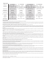
If... Then... Fix...
Amplifier does not turn on B+ or REM not between 10.5 and 15.5 or no voltage present Check the alternator, battery, fuse, and wiring. Repair as
necessary
Amplifier Noise Amplifier is not properly grounded Check wiring and repair as necessary
Turn-On Pop Voltage spike from source unit is entering amplifier’s input Connect a relay turn-on module to REM terminal if pops are
eliminated with no input signal to amplifier
Engine Noise Noise is radiating into signal cables Re-route signal cables away from sources of high current
Troubleshooting
1230-56436-02
08/2010 E.W.R.
-
 1
1
-
 2
2
-
 3
3
-
 4
4
-
 5
5
-
 6
6
-
 7
7
-
 8
8


Audio Design LA-1000MD Le manuel du propriétaire
- Catégorie
- Amplificateurs audio de voiture
- Taper
- Le manuel du propriétaire
dans d''autres langues
Documents connexes

Autres documents
-
 Lightning Audio LA-8004 Manuel utilisateur
-
 In Phase IPA 4001D Manuel utilisateur
-
Bazooka MGA11000H Manuel utilisateur
-
Rockford Fosgate R1200-1D Manuel utilisateur
-
Prime R600X5 Installation & Operation Manual
-
 Phoenix Gold SX2 1200W Monoblock Amplifier SX2 Manuel utilisateur
-
 Rockford Fosgate T2500-1bd Manuel utilisateur
-
 Rockford Fosgate Power T2500-1bd CP Manuel utilisateur
-
Lanzar Car Audio MAXP 1601D Manuel utilisateur
-
 Lightning Audio LA-4100MINI Manuel utilisateur


