
OPERATION MANUAL
NOTICE D’EMPLOI
BEDIENUNGSANLEITUNG
P-7156-965
QXPDQXDoc
9/16
© 2016 by C.E. Studio-2 s.l. - Spain (EEC)
http://www.ramaudio.com
e-mail: [email protected]
Professional Power Amplifiers
MDi2 1K4-2K7-6K
MDi4 2K4-6K-12K
MDi8 2K7-6K
MDi
Series
(Screw/Phoenix Version)

WARNING:
The exclamation point inside an
equilateral triangle indicates the existen-
ce of internal components whose substi-
tution may affect safety.
The lightning and arrowhead symbol
warns about the presence of uninsula-
ted dangerous voltage.
To avoid fire or electrocution risk do not
expose the unit to rain or moisture.
To avoid electric shock, do not open the
unit. No user serviciable parts inside. In
the case of disfunction, have the unit
checked by qualified agents.
Class I device.
SAFETY
PRECAUTIONS
AVERTISSEMENTS
SICHERHEITSHINWEISE
CAUTION
RISK OF ELECTRIC SHOCK
DO NOT OPEN
ACHTUNG!:
Das Ausrufezeichen innerhalb eines
Dreiecks weist darauf hin, dass der
Austausch interner Bauteile die
Sicherheit beeinflussen kann.
Das Blitzzeichen zeigt die Gegenwart
unisolierter gefährlicher Spannungen
an.
Um Brand oder elektrische Schläge zu
vermeiden, darf diese Einheit
keiner starken Luftfeuchtigkeit oder
Regen ausgesetzt werden.
Um elektrische Schläge zu vermeiden,
öffnen Sie diese Einheit nicht. Bei
Reparaturbedarf wenden Sie sich an
qualifiziertes Personal.
Es handelt sich um ein Gerät der
Klasse I.
1
VORSICHT
GEFAHR EINES
ELEKTRISCHEN SCHLAGES.
NICHT ÖFFNEN!
RÈGLES DE SÉCURITÉ:
Le trinagle ponctué du point d’exclama-
tion central indique l’existence de com-
posants internes affectant la sécurité de
personnes non agrées par nos S.A.V..
Le symbole éclair indique la présence
de points électriques internes non iso-
lés.
Pour écarter tout risque d’incendie ou
d’électrocution, ne pas exposer l’appa-
reil à la pluie ni à l’humidité.
Afin d’éviter tout risque, ne pas ouvrir
l’appareil. Ne confier l’entretien de l’ap-
pareil qu’à du personnel technique qua-
lifié et agréé.
Appareil de Classe I.
ATTENTION
RISQUE DE CHOC ÉLECTRIQUE
NE PAS OUVRIR

0 Safety Precautions
1 General Information
1.1 Introduction
1.2 Main Characteristics
2 Controls: Where and What?
2.1 Front Panel
2.2 Rear Panel
3 Installation and Operation
3.1 Connections
3.1.1 Dual Channel Mode
3.1.2 Bridge Channel Mode
3.2 Configuration
3.3 Troubleshooting
4 Technical Specifications
4.1 Data
©2016 by C.E. Studio-2 s.l.
Pol.Ind. La Figuera
C/ Rosa Luxemburgo nº34
46970 Alaquas - Valencia - SPAIN
Phone: +34 96 127 30 54
Fax: +34 96 127 30 56
http://www.ramaudio.com
e-mail: [email protected]
P-7156-965 QXPDQXDoc 9/16
RAM Audio
®
, FCM
™
, SSP
™
, ICL
™
and
QuantaPulse
™
are registered trade-
marks of C.E. Studio-2 s.l. All other
names are trademarks of their respecti-
ve companies.
0 Sicherheitshinweise
1 Allgemeine Anweisungen
1.1 Einleitung
1.2 Allgemeine Eigenschaften
2 Lokalisierung der Funktionen
2.1 Frontplatte
2.2 Rückplatte
3 Anschluss- und Inbetriebnahme
3.1 Anschlüsse
3.1.1 Dual Kanalmodus
3.1.2 Bridge Kanalmodus
3.2 Konfiguration
3.3 Problemlösung
4 Technische Spezifikationen
4.1 Technische Daten
INHALTSVERZEICHNIS
INDEX
0 Avertissements
1 Informations Générales
1.1 Introduction
1.2 Caractéristiques générales
2 Commandes et fonctions
2.1 Panneau avant
2.2 Panneau arrière
3 Installation et mise en route
3.1 Branchements
3.1.1 Mode DUAL
3.1.3 Mode BRIDGE
3.2 Configuration
3.3 Dysfonctionnements éventuels
et dépannage.
4 Spécifications
4.1 Données téchniques
TABLE DES MATIÈ-
RES
2

The MDi Series of amplifiers has been
specifically developed for fixed installa-
tion and/or network applications. Thus
they are equipped with specific connec-
tors: Euro style input and screw terminal
barrier strip output, to offer clear, direct
and hassle-free connectivity.
Furthermore they offer up to eight inde-
pendent channels per unit to allow for
as many zoning possibilities. Their uni-
tary power output is dimensioned to suit
specifically that type of installations.
The MDi Series incorporate unique
absolute protections as the FCM™ or
SSP™ systems.
• Eight, four and two channel models.
• Ultra-compact and lightweight 2-U
high.
• Laser cut aluminum front panel.
• FCM™ Faulty Channel Management
system to avoid entire device shut-
down.
• State-of-the-art layout for maximum
performance and reliability.
• Detented sealed potentiometers for
easy recall of volume settings.
• ICL, PROT, SIGNAL indicators per
channel.
• Optional Add-on card to interface with
third party alarm systems with GPIO
connections.
• ICL clip-limiters.
• Switchable (35Hz) sub-sonic highpass
filter per channel.
• All channels bridgeable by pairs.
• Temperature and signal dependant,
intelligent cooling system for minimal
noise.
• Highly oversized thermal dissipation
design for maximum reliability.
1.2 Main Characteristics
1.1 Introduction
Die Verstärker der MDi- Serie wurde
spezifisch für Festinstalationen un
Netzanwendungen entwickelt. Deshalb
ist diese Serie mit spezifischen
Anschlüssen versehen, um immer klare
und problemlose Verbindungen zu bie-
ten: Euro-typ Eingang und
Schraubleisten – Output. Ausserdem
bieten die bis zu acht unabhängigen
Kanäle pro Einheit die Möglichkeit viele
Zonen zu beschallen. Die
Ausgangsleistungen der Einheiten sind
so dimensoniert, dass sie genau an
diese art Installierungen angepasst
sind.
Die MDi-Reihe verfügt über einzigartige
Schutzsysteme wie FCM™ und SSP™.
• Acht, Vier- und Zwei-Kanal-Modelle.
• Ultrakompakt und leichtgewichtig, 2U
hoch.
• Lasergeschnittene Frontplatte.
• Der modernste Schaltungsentwurf ver-
sichert Ihnen Leistung und
Zuverlässigkeit.
• Wahlweise gibt es Zusatzschaltungen
als Schnittstelle für Alarmsysteme drit-
ter Hersteller, mit GPIO Anschlüssen.
• Versiegelter Potentiometer mit 21
Stufen für den einfachen Abruf von
Volumeneinstellungen.
• ICL-, PROT- und Signalanzeiger pro
Kanal.
• Alle Kanäle können paarweise
gebrückt werden.
• ICL Cliplimiter.
• Schaltbare (35Hz) Subssonic-
Hochpassfilter pro Kanal.
• Ein Temperatur- und signalabhängi-
ges, intelligentes Kühlsystem bietet
minimale Geräuschpegel.
• Sehr überdimensioniertes Kühlsystem,
entworfen für eine maximale
Zuverlässigkeit.
1.2 Allgemeine Eigenschaften
1.1 Einleitung
General Information
Nous avons développé la Série d'ampli-
ficateurs "MDi" pour des utilisations
spécifiques en installation fixe et/ou de
réseau. Pour cette raison, ils sont équi-
pés avec des connecteurs adaptés à
ces utilisations: bloc Euro-style pour les
entrées et barrette de connexions à vis
pour les sorties, de façon à obtenir une
connectique claire, directe et sans com-
plications. De plus, l'ampli offre jusqu'à
huit canaux indépendants pour sonori-
ser autant de zones avec des program-
mes différents. La puissance de sortie
de chaque canal est dimensionnée
tenant compte des utilisations particuliè-
res de ces amplis.
La Série MDi incorpore aussi des systè-
mes de protection absolue tels que: Le
FCM™ ou le SSP™.
• Modèles de huit, quatre et deux
canaux.
• Ultra-compact et léger, 2-U en hau-
teur.
• Face avant en alu découpée au laser.
• FCM™ (Faulty Channel Management)
système qui évite la mise en stand-by
de tout l'appareil.
• Aménagement des circuits optimisé
pour obtenir un rendement et une fia-
bilité maxi.
• Potentiomètres crantés et étanches
pour un calage facile des niveaux.
• Signalisation par LED de ICL, PROT,
Surchauffe et Signal.
• Cartes électroniques rapportées
optionnelles qui permettent le coupla-
ge avec des systèmes d'alarme avec
connections GPIO d'autres fabricants.
• Limiteurs d'écrêtage ICL.
• Filtre passe-haut/subsonique aux
35Hz au choix par canal.
• Pontage de tous les canaux par pai-
res.
• Système intelligent de refroidissement
dépendant du signal et de la tempéra-
ture.
• Dissipation thermique surdimension-
née pour une fiabilité accrue.
1.2 Caractéristiques Générales
1.1 Introduction
Informations
Générales
Allgemeine
Anweisungen
3

Lokalisierung der
Funktionen
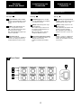
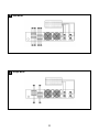
See Figure
Signal attenuation level control
knobs: Permit independent control
of each channel’s attenuation (21
steps).
SIGNAL: This LED indicates pre-
sence of signal at the inputs.
OK : This LED shows temperature
protection is active (Red).
ICL: LED indicating Intelligent Clip
Limiter in operation.
Main Power Switch:
Position I: Connects the amplifier's
current feed. (OK green LED on).
Position O disconnects the Power.
3
2
2.1 Front Panel
1
1
Siehe Fig.
Lautstärkeregler: diese ermögli-
chen die Signalstärke am Ausgang
in 21 Stufen zu regeln.
SIGNAL: Wachanzeige des einge-
henden Signals.
OK : LED-Anzeige leuchtet wenn
der Schutz vor Überwärmung ein-
geschaltet ist (Rot).
ICL: Die LED zeigt an, dass der
Intelligent Cliplimiter arbeitet.
Beleuchteter Hauptstromschalter:
Position I: Schaltet die Endstufe ein.
(OK grün LED leuchtet).
Position O Schaltet die Endstufe
aus.
6
2
2.1 Frontplatte
1
1
Controls:
Where and What?
Voir Fig.
Atténuateurs de signal d’entrée
crantés: réglage du niveau d’entrée
indépendant sur chaque canal.
SIGNAL: indique la présence de
signaux d’entrée.
OK: signalisation par LED de tem-
perature excessive (Rouge).
ICL: signalisation par LED de le
fonctionnement de le
système ICL.
Power:
Position I: Connecte l'appareil au
courant, (OK LED vert allumée).
Position O: Interruption de la mise
sous tension.
3
2
2.1 Panneau Avant
1
1
Commandes et
Fonctions
4
1
Front Panel
2
1
2
1
3

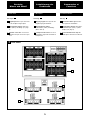
See Figure
Signal Input: Euro style connectors
for the amplifier’s signal input.
Configuration Switch: Sub sonic
filter (35Hz), and Bridge (see page
9).
Speaker connectors: screw termi-
nal barrier strip to connect the spea-
kers.
3
2.2 Rear Panel
2
1
2
Siehe Fig.
Eingangssignal: Euro style für den
Signaleingang der Endstufe.
Konfigurationsschalter:
Subsonicfilter (35Hz), und Bridge
(Siehe Seite 9).
Lautsprecheranschluss: screw ter-
minal barrier strip zum Anschluss an
Lautsprecher.
2.2 Rückplatte
3
2
1
2
Lokalisierung der
Funktionen
5
Controls:
Where and What?
Voir Fig.
Connecteurs Euro style d’entrée
des signaux de modulation.
Configuration Switch: filtre passe-
haut/subsonique (35Hz), et ponté
(bridge) (voir page 9).
Screw terminal barrier strip de
sortie pour le branchement des HP.
2
2.2 Panneau Arrière
3
2
1
Commandes et
Fonctions
2
Rear Panel
1
2
2
3
3
1

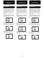
The Power switch must always be on
the “Off” position before plugging the
amp to a properly earthed mains soc-
ket (220-240V AC / 110V-120V AC).
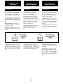
The input signal fed to the amplifier can
be either balanced or un-balanced. The
drawing below describes both ways to
wire an Euro style connector for the pur-
pose.
Balanced Signal: Connect pin to
Ground, pin + to Signal + (hot) and pin
-
to Signal
-
(cold).
Unbalanced Signal: Connect Pin to
Ground, pin + to Signal and pin
-
to
Ground.
Important!: If a connection is done with
a un-balanced line and pin
-
on the
Euro style is not connected to ground, a
6 dB loss occurs in the line and only a
quarter of the amplifier power is produ-
ced.
3.1 Connections
Bevor Sie diese Einheit an eine
SHUKO-Steckdose anschließen, schal-
ten Sie den Hautstromschalter aus.
Das Eingangssignal kann entweder
symmetrisch oder unsymmetrisch sein.
Für den Anschluss siehe Zeichnung.
Symmetrisches Signal: Die Belegung
der Euro style Pins ist wie folgt:
Masse, + Positives Signal (hot),
-
Negatives Signal (cold).
Asymetrisches Signal: Die Belegung
der Euro style Pins ist wie folgt:
Masse, + Signal,
-
Masse.
ACHTUNG! Wenn Sie ein asymetris-
ches Signal anschließen und Pin
-
nicht
an Masse anschließen, erzeugt dies
einen Verlust von 6dB (1/4 der Leistung
der Endstufe) am Ausgangssignal.
3.1 Anschlüsse
Installation and
Operation
Veillez à ce que l’interrupteur de mise
en service soit en position “Off” avant
de brancher l’appareil sur une prise
secteur avec mise à la terre (220V-
240V AC / 110V-120V AC).
L’appareil peut fonctionner avec des
signaux symétriques ou assymétriques.
La figure ci-dessous indique le câblage
des connecteurs Euro style pour les
deux cas.
Câblage Symétrique: souder la broche
à la masse, la broche + au point
chaud (+), et la broche
-
au point froid
(
-
).
Câblage Assymétrique: souder les
broches et
-
à la masse, et la broche
+ au signal.
Important: Si on effectue le branche-
ment d’un signal asymetrique sur le
connecteur Euro style sans relier la bro-
che
-
à la masse, une perte de 6dB
sera constatée , ce qui se traduira par
une perte du 75% de la puissance de
sortie.
3.1 Branchement
Installation et
mise en service
Anschluss und
Inbetriebnahme
Balanced Wiring
Ground
+ Signal +
-
Signal
-
Unbalanced Wiring
Ground
+ Signal
-
Ground
6

Installation and
Operation
Installation et
mise en service
The amplifier can operate on two diffe-
rent configurations: DUAL or BRIDGE.
The connections for the two modes are
different.
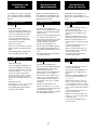
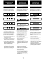
See Figure
- Switch “Off” the amp.
- Set the Configuration Minidips on the
rear panel to NO Bridge (see page 9).
- Connect the signal lines to the Euro
style connectors on all channels.
- Connect the speakers’ lines to the
corresponding screw terminal on the
amp respecting the polarity.
- Switch “On” the amp.
- Use the level control knob on the front
panel to adjust each channel indepen-
dently.
- Each signalling LED group will show
its corresponding channel status.
See Figure
- Switch “Off” the amp.
- Set the Configuration Minidips on the
rear panel to “BRIDGE” (see page 9).
- Connect a signal line to the Euro style
connectors Channel “1”, “3”, “5” or “7”.
- Connect the speaker line wired to
CH1(+) and CH2(-) (“3”&“4”, “5”&“6” or
“7”&“8”) screw terminals. In this way
pin CH1(+) is the positive.(also “3”, “5”
or “7”).
- Switch “On” the amp.
- Use Channel “1” (“3”, “5” or “7”) control
knob to adjust the amp’s output.
- The signalling LED groups will show
the single channel status.
3
3.1.1 DUAL Channel Mode
4
3.1.2 BRIDGE Channel Mode
L’amplificateur peut fonctionner en
mode stéréo ou ponté (Bridge). Le
branchement est différent pour ces trois
modes.
Voir Fig.
- Commuter l’interrupteur de mise en
service sur position “Off”.
- Sélectionner le mode “DUAL” sur le
panneau arrière de l’appareil (voir
page 9).
- Bancher les signaux d’entrée aux
fiches Euro style de touts les canaux.
- Brancher les haut-parleurs sur les
screw terminal en respectant les pola-
rités.
- Commuter l’interrupteur de mise en
service sur position “On”.
- Utiliser les atténuateurs d’entrée en
face-avant pour régler le niveau de
sortie de chaque canal.
- Les indicateurs LED afficheront le
stade de chaque canal.
Voir Fig.
- Commuter l’interrupteur de mise en
service sur position “Off”.
- Sélectionner le mode BRIDGE sur le
panneau arrière de l’appareil (voir
page 9).
- Brancher le signal modulation sur le
connecteur Euro style du Canal “1”,
“3”, “5” ou “7”.
- Brancher les HP sur les CH1(+) et
CH2(-) (“3”&“4”, “5”&“6” ou “7”&“8”)
screw terminal de sortie des canaux.
Le canal CH1(+) (“3”, “5” ou “7”) est la
borne + dans ce mode de fonctionne-
ment.
- Commuter l’interrupteur de mise en
service sur position “On”.
- Utilisser les atténuateur d’entrée du
Canal “1” (“3”, “5” ou “7”) pour ajuster
le signal de sortie.
- Les rangées de LED afficheront le
niveau de sortie.
3
3.1.1 Mode Stéréo
4
3.1.2 Mode Ponté (BRIDGE)
Es gibt zwei Funktionsmöglichkeiten
dieser Endstufe: Dual und Bridge (ste-
reo und mono). Die Anschlüsse sind in
beiden Fällen verschieden:
Siehe Fig.
- Schalten Sie die Endstufe aus.
- Stellen Sie den Modusschalter auf der
Rückseite auf die Position NO Bridge
(Siehe Seite 9).
- Schließen Sie alle Eingangssignale an
ihre entsprechenden Euro style.
- Schließen Sie die Lautsprecher an die
entsprechenden screw terminal an,
bitte die Polarität ist beachten.
- Schalten Sie die Endstufen ein.
- Benutzen Sie die Lautstärkeregelung
der entsprechenden Kanäle um den
gewünschten Lautstärkepegel zu errei-
chen.
- Die LED-Anzeigen geben den Status
der beiden Kanäle an.
Siehe Fig.
- Schalten Sie die Endstufe aus.
- Setzen Sie den Konfigurationsschalter
auf der Rückseite auf die Position
“BRIDGE” (Siehe Seite 9).
- Schließen Sie das Eingangssignal an
die Euro style “1”, “3”, “5” und “7”
- Schliessen Sie den Lautsprecher an
beide CH1(+) / CH2(-) Buchsen der
beiden Kanäle an, wobei positiv der
roten Buchsen des CH1(+) - Kanals
entspricht.
- Schalten Sie die Endstufen ein.
- Benutzen Sie Kanal “1” (“3”, “5” und
“7”) Potentiometer für die Regulierung
des Endstufenaus-ganges.
- Die LED-Anzeigen werden den Status
des Ausgangkanals angeben.
3
3.1.1 DUAL Kanalmodus
4
3.1.2 Bridge Kanalmodus
7
Anschluss und
Inbetriebnahme

3
Dual Mode
8
4
Bridge Mode

The amplifier has an ensemble of mini-
dips on the back panel, which allow for
the following configurations: the high-
pass subsonic filter, the Gain selection
and the bridge mode. All these configu-
rations can be cross-set in any way,
independently from the others. The
basic configuration possibilities are as
follows:
Standard Configuration: the amplifier
works without high pass subsonic filter,
and no Bridge mode.
Sub-sonic Filter Enabled: the amplifier
works with Channel 1 high pass subso-
nic filter (35Hz), and no Bridge mode.
Bridge Mode: the amplifier works with-
out high pass subsonic filter, and
Channel 1/Channel 2 Bridge mode.
3.2 Configuration
Das Mini-dip-Ensemble auf der
Rückplatte der Endstufe ermöglicht fol-
gende Konfigurationen: der Subsonic-
Hochpassfilter, Pegelwerte und den
Bridgemodus. Diese Konfigurationen
lassen sich, unabhängig von den übri-
gen, in jeglicher Weise kombinieren. Die
Basiskonfigurations-möglichkeiten sind
wie folgt:
Standartkonfiguration: Die Endstufe
arbeitet ohne Subsonic-Hochpassfilter,
und ohne Bridgemodus.
Subsonicfilter eingeschaltet: Die
Endstufe arbeitet mit Subsonic-
Hochpassfilter (35Hz), und ohne
Bridgemodus.
Bridgemodus: Die Endstufe arbeitet
ohne Subsonic-Hochpassfilter, und
Bridgemodus.
3.2 Konfiguration
Installation and
Operation
L'amplificateur a un ensemble de mini-
dips sur la face arrière qui permettent la
configuration des éléments suivants: fil-
tre passe-hauts-subsonique, sensibilité
et ponté des canaux. Toutes ces confi-
gurations peuvent s'ajuster individuelle-
ment, de façon indépendante. Les pos-
sibilités basiques de ces configurations
peuvent être:
Configuration Standard: l'amplificateur
travaille sans le filtre passe-hauts/sub-
sonique, et la configuration ponté deac-
tivée.
Filtre subsonique activé: le filtre
passe-hauts/subsonique est activé
(35Hz), et la configuration ponté deacti-
vée.
Ponté activé: le filtre passe-hauts/sub-
sonique est deactivée, et la configura-
tion ponté activé.
3.2 Configuration
Installation et
mise en service
9
Anschluss und
Inbetriebnahme

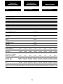
In the event of incorrect connection or
misfunctioning, the amp will activate
one or more of its LED to warn about
the problem.
Correct function: SGNL lights to indi-
cate signal presence. (OK Green)
ICL: The Intelligent Clip Limiter is ope-
rating.
No Signal: No Input Signal is reaching
the amp.
Protections: (OK Red) Several causes
can trigger this LED, most common are:
- Overheating: The amplifier has rea-
ched the maximum operational tempe-
rature. Most common cause is: the nor-
mal air flow is blocked, accumulated
dirt, dust or object leaning against the
grill. Check and clean periodically.
- Short-circuit in the speakers’ line or in
the speakers themselves.
- Low Impedance: check speakers’ con-
nections or possible speaker disfunc-
tion.
- DC in the output: the protections are
activated to avoid damage to the spe-
akers, the unit must be sent in for
repair to a qualified technician.
- Delayed Start: As you switch on the
amp the output to the speakers is dis-
connected. After a few seconds the
amp will connect the speakers and
proceed with normal functioning.
3.3 Troubleshooting
Sollte sich eine Fehlfunktion ergeben,
wird diese durch die LED-Anzeigen auf
der Frontplatte angezeigt. Es gibt fol-
gende Möglichkeiten:
Korrektes Arbeiten: SGNL leuchtet
wenn Eingangssignal vorhanden ist.
(OK Grün)
ICL: Der Intelligent Clip Limiter ist in
Betrieb.
Kein Eingangssignal: Kein
Eingangssignal vorhanden.
Schutzschaltungen: (OK Rot) Der
Eingriff der Schutzschaltungen kann
sich durch folgende Gründe auslösen:
- Überhitzung: Die Endstufe hat die
maximale Arbeitstemperatur erreicht.
Die häufigste Ursache ist
Verschmutzung oder Blockierung der
Luftein- und Austritte. Es ist ratsam
diese regelmäßig zu säubern.
- Kurzschluss: die Anschlusskabel oder
ggf. die Lautsprecher auf
Kurzschlüsse prüfen.
- Unangebrachte Impedanz: Die
Impedanz der Ausgänge ist zu niedrig.
Instalation auf Fehlanschlüsse testen
oder ggf. Lautsprecher auf Fehler prü-
fen.
- Gleichstrom: Die Schutzschaltung
greift ein, um die Zerstörung der
Lautsprecher zu vermeiden. Die
Endstufe muss von einem qualifizier-
tem Techniker überprüft werden.
- Soft Start: Während des
Inbetriebnahme der Endstufe werden
die Lautsprecher zeitlich ausgeschal-
tet, um einen möglichen Schaden zu
vermeiden. Nach einigen Sekunden
schaltet die Endstufe die Lautsprecher
automatisch ein.
3.3 Problemlösung
Installation and
Operation
En cas d’utilisation incorrecte ou de
dysfonctionnement, une ou plusieurs
LED seront allumées pour indiquer la
nature du problème.
Fonctionnement correct: SGNL Diode
Vert allumée. (OK Vert)
ICL: .Fonctianement du Limiteur
Intelligent d'écretage.
Aucun Signal n’arrive à l’Ampli.
Protections: (OK Rouge) Plusieurs
anomalies peuvent déclencher cet affi-
chage. Les plus courantes sont:
- Surchauffe: l’amplificateur a atteint sa
plus haute température interne admissi-
ble. Le plus souvent ceci est dû à un
blocage ou à l’obturation des voies de
ventilation.
- Court-circuit sur ligne HP.
- Impédance trop basse pour un fonc-
tionnement à pleine puissance.
- Courant continu en sortie. Cette pro-
tection est activée pour ne pas
endommager les HP. Confier l’appareil
en SAV à un technicien agréé.
- Temporisation à la mise sous tension.
Les signaux de sortie sont atténués
pendant quelques secondes.
3.3 Dysfonctionnements éventuels
Installation et
mise en route
10
Anschluss und
Inbetriebnahme
ICLOKSGNL ICLOKSGNL ICLOKSGNL
ICLOKSGNL
ICLOKSGNL
ICLOKSGN
ICLOKSGNL
ICLOKSGNL
ICLOKSGNL
ICLOKSGNL
ICLOKSGNL
ICLOKSGNL

4.2 Data 4.2 Données techniques4.2 Technische Daten
Technical
Specifications
Spécifications
Technische
Spezifikationen
11
Technical Specifications
MDi2-1K4 MDi2-2K7 MDi2-6K MDi4-2K4 MDi4-6K MDi4-12K MDi8-2K7 MDi8-6K
Max. Output Power
@ 4ohm 2x700 W 2x1350 W 2x3000 W 4x610 W 4x1500 W 4x3000 W 8x340 W 8x750 W
@ 8ohm 2x375 W 2x900 W 2x1500 W 4x350 W 4x800 W 4x1500 W 8x225 W 8x400 W
Bridge @ 8ohm 1x1400 W - - 2x1220 W - - 4x680 W 4x1500 W
High Z
70Vrms/100Vpeak - 2x1350 W - - 4x1500 W - 4x680 W -
100Vrms/140Vpeak 1x1400 W - 2x3000 W 2x1200 W - 4x3000W 4x1500 W
Frequency Response
Power Bandwidth ±0.25dB 20Hz-20kHz
Phase Response
@ 1 watt 20Hz-20kHz ±15 deg
Total Harmonic Distortion
20Hz-20kHz <0.05%
Intermodulation Distortion
SMPTE <0.05%
Damping Factor
(20Hz-500Hz @8ohm) >400
Crosstalk
20Hz-1kHz >75 dB
Voltage Gain 32dB
Sensitivity
Rated Power @ 8W 1.4 V 2.1 V 2.8 V 1.3 V 2 V 2.8 V 1.1 V 1.4 V
Signal-to-Noise Ratio
20Hz-20kHz 101 dBA 103 dBA 104 dBA 105 dBA 101 dBA 103 dBA 104 dBA 104 dBA
Required AC Mains
170V-265V AC - 50Hz/60Hz
@4ohm (1/8 rated power) 1.8 A 4 A 4.5 A 3.2 A 4.5 A 9 A 4 A 4.5 A
Dimensions
W x H x D (mm) 483x89x280 483x89x280 483x89x280 483x89x280 483x89x400 483x89x400 483x89x400 483x89x400
W x H x D (inches) 19x3.5x11 19x3.5x11 19x3.5x11 19x3.5x11 19x3.5x15.7 19x3.5x15.7 19x3.5x15.7 19x3.5x15.7
Weight
Net 5kg-11lb 5kg-11lb 5.5kg-12.1lb 5kg-11lb 5kg-11lb 6kg-13.2lb 5.5kg-12lb 5.5kg-12lb
Protections
Soft-start, Turn-on Turn-off muting, Over-heating, DC, RF, Short-circuit, Open or mismatched loads, Overloaded power supply, ICL™ and
FCM™.

Manufactured in the EU by C.E. Studio-2 s.l.
Pol. Ind. La Figuera - C/ Rosa Luxemburgo nº34
46970 Alaquas - Valencia - SPAIN
Phone: +34 96 127 30 54 Fax: +34 96 127 30 56
http://www.ramaudio.com e-mail: [email protected]
-
 1
1
-
 2
2
-
 3
3
-
 4
4
-
 5
5
-
 6
6
-
 7
7
-
 8
8
-
 9
9
-
 10
10
-
 11
11
-
 12
12
-
 13
13


dans d''autres langues
- English: RAM MDi2-2K7 User manual
- Deutsch: RAM MDi2-2K7 Benutzerhandbuch