Jenn-Air JS48NXFXDW01 Guide d'installation
- Catégorie
- Frigos
- Taper
- Guide d'installation
Ce manuel convient également à

JENN-AIR_SIDEBYSIDEBUILT-INREFRIGERATOR
REFRIGERADOREMPOTRADO
DEDOSPUERTASJENN-AII_
RI_FRIGI_RATEURENCASTRI_COTE.,_CO'IEJENN-AII_
INSTALLATIONGUIDE
For questions about features, operation/performance, parts, accessories, or service, call:
1-800-JENNAIR (1-800-536-6247) or visit our website at www.jennair.com.
In Canada, call: 1-800-807-6777, or visit our website at www.jennair.ca.
GUIIA DEINSTALACION
Si tiene preguntas respecto a las caracteristicas, funcionamiento, rendimiento, partes, accesorios o servicio tecnico, Ilame al:
1-800-JENNAIR (1-800-536-6247) o visite nuestro sitio de internet: www.jennair.com.
En CanadA, Ilame al: 1-800-807-6777, o visite nuestro sitio de internet: www.jennair.ca.
GUIDED'INSTALLATION
Au Canada, pour assistance, installation ou service, composez le 1-800-807-6777 ou visitez notre site web &www.jennair.ca.
Table of Contents/[ndice/Table des matieres ...................................................................................... 2
JENN-AIR°
W10379136B

TABLEOF CONTENTS
REFRIGERATOR SAFETY ............................................................. 3
MODELS .......................................................................................... 4
Accessories .................................................................................. 5
INSTALLATION REQUIREMENTS ................................................ 5
Tools and Parts ............................................................................ 5
Location Requirements ................................................................ 7
Electrical Requirements ............................................................... 8
Water Supply Requirements ........................................................ 8
Product Dimensions ..................................................................... 9
Tipping Radius ............................................................................. 9
Door Swing Dimensions ............................................................... 9
Cabinet and Panel Installation Options ..................................... 10
Fully Integrated Grille Installation Requirements ....................... 11
Standard Integrated Grille Installation Requirements ................ 12
Panel Kit Installation Requirements ........................................... 12
Custom Wood Overlay Panels ................................................... 13
Custom Wood Overlay Panel Dimensions ................................. 13
INSTALLATION INSTRUCTIONS ................................................ 14
Unpack the Refrigerator............................................................. 14
Move the Refrigerator into House .............................................. 14
Install Anti-Tip Boards ................................................................ 15
Connect the Water Supply ......................................................... 15
Plug in Refrigerator ..................................................................... 17
Install Side Trims ........................................................................ 17
Move Refrigerator to Final Location........................................... 17
Level and Align Refrigerator ....................................................... 18
Install Refrigerator and Panels ................................................... 19
Install Handles ............................................................................ 23
Install Base Grille ........................................................................ 24
Complete Installation.................................................................. 24
[NDICE
SEGURIDAD DEL REFRIGERADOR ........................................... 25
MODELOS ..................................................................................... 26
Accesorios .................................................................................. 27
REQUlSITOS DE INSTALACION ................................................. 27
Piezas y herramientas ................................................................ 27
Requisitos de ubicacion ............................................................. 29
Requisitos electricos .................................................................. 30
Requisitos del suministro de agua ............................................. 30
Medidas del producto ................................................................ 31
Arco de vuelco ........................................................................... 32
Medidas de oscilacion de las puertas ....................................... 32
Opciones para la instalacion del armario y los paneles ............ 32
Requisitos para la instalacion de la rejilla
completamente incorporada ...................................................... 33
Requisitos para la instalacion de la rejilla
incorporada estandar ................................................................. 35
Requisitos de instalacion del juego de paneles ........................ 35
Paneles de madera recubiertos a la medida ............................. 36
Dimensiones del panel de madera recubierto ........................... 36
INSTRUCCIONES DE INSTALACION ......................................... 37
Desempaque el refrigerador ...................................................... 37
Como introducirel refrigerador en la casa ................................ 37
Como instalar los tableros antivuelco ........................................ 38
Conexion del suministro de agua .............................................. 38
Como enchufar el refrigerador ................................................... 40
Instalacion de las molduras laterales ......................................... 40
Como mover el refrigerador a su ubicacion final ....................... 41
Nivelacion y alineamiento del refrigerador ................................. 41
Instalacion del refrigerador y los paneles .................................. 42
Instalacion de las manijas .......................................................... 47
Instalacion de la rejilla de la base .............................................. 47
Como terminar la instalacion ..................................................... 48
TABLEDESMATIERES
SI_CURITI_ DU RI_FRIGI_RATEUR .............................................. 49
MODI=LES ..................................................................................... 50
Accessoires ................................................................................ 51
EXIGENCES D'INSTALLATION ................................................... 51
Outillage et pieces ...................................................................... 51
Exigences d'emplacement ......................................................... 53
Specifications electriques ......................................................... 54
Specifications de I'alimentation en eau ..................................... 54
Dimensions du produit ............................................................... 55
Rayon de basculement .............................................................. 56
Dimensions pour le pivotement des portes ............................... 56
Options d'installation du placard et du panneau ...................... 56
Specifications d'une installation grille totalement int6gree .......57
Criteres d'une installation grille integr6e standard .................... 59
Specifications pour I'installation
de I'ensemble de panneaux ....................................................... 59
Panneaux de bois decoratifs personnalises .............................. 60
Dimensions des panneaux de bois
decoratifs personnalises ............................................................ 60
INSTRUCTIONS D'INSTALLATION ............................................. 61
Deballage du r6frigerateur .......................................................... 61
Faire entrer le refrig6rateur dans le domicile ............................. 61
Installation de planches antibasculement .................................. 62
Raccordement &I'alimentation en eau ...................................... 62
Branchement du le r6frigerateur ................................................ 64
Installation des garnitures laterales ............................................ 64
Deplacement du refrig6rateur & son emplacement definitif ......65
Reglage de I'aplomb et alignement du refrig6rateur ................. 65
Installation du r6frigerateur et des panneaux ............................ 66
Installation des poignees ............................................................ 71
Installation de la grille de la base ............................................... 72
Achever I'installation .................................................................. 72
2

REFRIGERATORSAFETY
Your safety and the safety of others are very important.
We have provided many important safety messages in this manual and on your appliance. Always read and obey all safety
messages.
This is the safety alert symbol.
This symbol alerts you to potential hazards that can kill or hurt you and others.
All safety messages will follow the safety alert symbol and either the word "DANGER" or "WARNING."
These words mean:
You can be killed or seriously injured if you don't immediately
follow instructions.
You can be killed or seriously injured if you don't follow
instructions.
All safety messages will tell you what the potential hazard is, tell you how to reduce the chance of injury, and tell you what can
happen if the instructions are not followed.
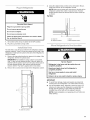
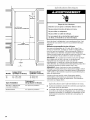
Tip Over Hazard
Refrigerator is top heavy and tips easily when not
completely installed.
Keep doors taped closed until refrigerator is
completely installed.
Use two or more people to move and install
refrigerator.
Failure to do so can result in death or serious injury.

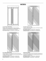
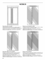
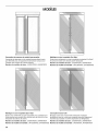
MODELS
/
i
i
Custom-Made Panel Design
Features custom-made panels and custom hardware
provided by the cabinetmaker for a seamless appearance
designed to blend with existing kitchen cabinetry.
Base Model Numbers: JS42NXFXDW, JS48NXFXDW
I r
Pro-Style ®Stainless Design
Features stainless steel wrapped doors and Pro-Style ®handles
with diamond-etched grip.
Base Model Numbers: JS42NXFXDW, JS48NXFXDW
Kit Model Numbers: JPK42SNXWPS, JPK48SNXWPS
] [
Euro-Style Stainless Design
Features stainless steel wrapped doors with new Euro-style
handles designed to compliment the Jenn-Air Euro kitchen suite
or enhance any kitchen decor.
Base Model Numbers: JS42NXFXDW, JS48NXFXDW
Kit Model Numbers: JPK42SNXWSS, JPK48SNXWSS
Oiled-Bronze Design
Features intricate copper strokes that integrate seamlessly into
your kitchen while slightly curved matching handles add to the
refrigerator's expressive form.
Base Model Numbers: JS42NXFXDW, JS48NXFXDW
Kit Model Numbers: JPKSNXWSR, JPK48SNXWSR

FloatingGlassDesign
Classicblackorwhiteglasspanelsthatseeminglyfloatinplace
withslightlycurved,colorcoordinatinghandlesthatwill
complimentyourcontemporarykitchen.
BaseModelNumbers:JS42NXFXDW,JS48NXFXDW
KitModelNumbers:
BlackGlass-JPK42SNXWSY,JPK48SNXWSY
WhiteGlass-JPK42SNXWSF,JPK48SNXWSF
AllfactorypartsareavailablethroughyourJenn-AirdealerorbycallingJenn-Airat1-800-JENNAIR(1-800-536-6247).InCanada,call
1-800-807-6777.
Door Handle Kits
These handle kits can be ordered to use on custom wood overlay
panels. Follow the kit instructions for installing the door handles.
Pro-Style ®Stainless Steel - W10250643
Euro-Style Stainless Steel - W10250640
Classic Euro-Style - W10250637
Armoire-Style Door Panel Kit
Follow the kit instructions for installation.
42" Model - W10292393
48" Model - W10292394
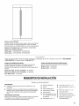
INSTALLATIONREQUIREMENTS
IMPORTANT:
• Installer: Leave Installation Instructions with the homeowner.
• Homeowner: Keep Installation Instructions for future
reference. Save these Installation Instructions for the local
electrical inspector's use.
Tools Needed:
Gather the required tools and parts before starting installation.
Read and follow the instructions provided with any tools listed
here.
• Cordless drill
• Drill bits
• Adjustable wrenches (2)
• Phillips screwdriver
• Small level
• 3/32"hex key
(panel kits only)
• 11/32" nut driver
• 3/8"and 1/2"open-end wrenches
• %2" and 3/le"hex key
• 1/4"and %e" socket drivers
• Tape measure
• Utility knife
• Tape (painters)
• Appliance dolly

PartsNeeded:
• #8x3"(7.6cm)woodscrews(longerscrewsmaybeneeded)(6)
• 2"x4"x32"(5cmx10cmx81cm)woodboard(s)(1or2)
• Customwoodoverlaypanels--consultaqualified
cabinetmakerorcarpentertomakethecustomwoodpanels.
See"CustomWoodOverlayPanels"formoreinformation.
Panelkits--See"36"Modelsor42"FrenchDoorModels"for
panelkitinformation.
• Flexible,codesapprovedwatersupplytubing,aferrule,a
unionanda1/4"(6.35ram)compressionfitting.
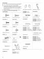
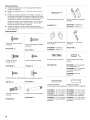
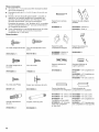
Parts Provided:
Slotted hex-head screw
W10141645 (21)
Hex-head blunt screw
W10142233 (4)
Phillips-head flat screw
8281251 (28)
Door Adjustment Pin
W10234194 5)
io r" }
Drawer Panel Bracket
W10203457 5)
Hex-head pointed screw
W10141189 (4)
Round-head screw
1163283 (24)
Door panel stud
W10129563 (4)
Door Stop Pin
W10234202 5)
%
Standard Integrated Grille
Bracket
W10182743-- Left (1)
W10182741--Right (1)
Fully Integrated Grille Bracket
W10260890-- Left (1)
W10260891 -- Right (1)
Panel top bracket
W10192849 (2)
RC Hinge Cover Trim
W10199873--42" SxS
W10199875--48" SxS
W10202875--36" BM (Right)
W10202510--42" FDBM (Right)
Panel templates
W10222281 --SxS
W10222279--BM
W10222283--Grille
Installation block
W10234156
Filler Board "L" Bracket
W10234199 5)
L,.
Top Grille Lower Trim
W10250961--36" BM (1)
W10250962--42" BM, SxS (1)
W10250963-- 48" SxS (1)
C
FC Hinge Cover Trim
W10199886--42"SxS
W10199888--48"SxS
W10202877--36" BM (Left)
W10202511--42"FDBM (Left)
Handle Side Door Trim
W10167367--SxS
W10188556-- BM (Left)
W10202604-- BM (Right)
W10202478-- FDBM (Right)
W10202480-- FDBM (Left)
6

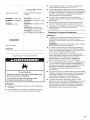
Explosion Hazard
Keep flammable materials and vapors, such as
gasoline, away from refrigerator.
Failure to do so can result in death, explosion, or fire.
IM PORTANT:
• Observe all governing codes and ordinances.
• It is recommended that you do not install the refrigerator near
an oven, radiator, or other heat source.
• Do not install in a location where the temperature will fall
below 55°F (13°C).
• Floor must support the refrigerator weight, more than 600 Ibs
(272 kg), door panels and contents of the refrigerator.
Flooring under refrigerator must be at same level as the room.
Face of cabinetry must be plumb.
• Ceiling height must allow for side tipping radius. See "Tipping
Radius."
• Location should permit door to open fully. See "Door Swing
Dimensions."
• Location must permit top grille removal. See "Opening
Dimensions."
0
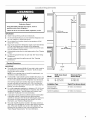
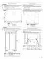
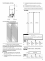
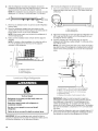
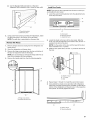
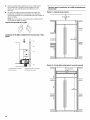
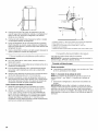
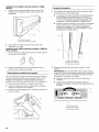
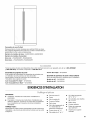
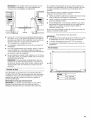
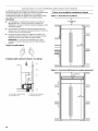
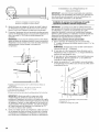
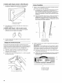
Opening Dimensions
IM PORTANT:
• The width of the opening (Width A), from side to side, must be
as specified for your model, for at least 2" (5.08 cm) back
from the face of the cabinet.
NOTE: If your opening does not meet this requirement, you
will need to make modifications.
• A solid soffit or wall cabinet must be installed 84" (213.4 cm)
above the floor. If the solid soffit is higher than 84" (213.4 cm)
or one is not available, then the refrigerator must be braced.
If the anti-tip boards are needed, they must be attached to
the rear wall studs so that there is 84" (213.4 cm) from the
bottom of the anti-tip board to the floor. See "Install Anti-Tip
Boards" for more information.
• For a fully integrated installation, a minimum of 6" (15.24 cm)
of open space above the refrigerator is required. See "Fully
Integrated Installation." Anti-tip boards are required. See
"Install Anti-Tip Boards" for more information.
• A grounded 3 prong electrical outlet should be located within
a specified number of inches from the right-hand side
cabinets or end panel. See the chart following the graphic for
the number of inches required for your model. For more
information, see "Electrical Requirements."
• The water shutoff should be located in the base cabinet on
either side of the refrigerator or some other easily accessible
area. If the water shutoff valve is not in the cabinets, the
plumbing for the water line can come through the floor. See
"Water Supply Requirements" for more information.
0
84" (213.4 cm)
to bottom of solid soffit
Dimension
77"
(196 cm)
A
Width
(see chart following)
r I'
t
C Depth
Width A (as shown Dimension B(as
Model above) shown above)
42 42" (106.7cm) 10" (25.4 cm)
48 48" (121.9cm) 16" (40.6 cm)
Installation Type Depth C (as shown above)
Standard Flush 25" (63.5 cm) minimum
(new installation)
Retrofit Installations 24" (60.9 cm) minimum

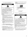
Electrical Shock Hazard
Plug into a grounded 3 prong outlet.
Do not remove ground prong.
Do not use an adapter.
Do not use an extension cord.
Failure to follow these instructions can result in death,
fire, or electrical shock.
Before you move your refrigerator into its final location, it is
important to make sure you have the proper electrical
connection.
Recommended Grounding Method
A 115 volt, 60 Hz., AC only, 15- or 20-amp fused, grounded
electrical supply is required. It is recommended that a separate
circuit serving only your refrigerator be provided. Use an outlet
that cannot be turned off by a switch. Do not use an
extension cord.
IMPORTANT: If this product is connected to a GFCI (Ground
Fault Circuit Interrupter) protected outlet, nuisance tripping of the
power supply may occur, resulting in loss of cooling. Food quality
and flavor may be affected. If nuisance tripping has occurred,
and if the condition of the food appears poor, dispose of it.
NOTE: Before performing any type of installation, cleaning, or
removing a light bulb, remove the top grille and turn the master
power switch to OFF or disconnect power at the circuit breaker
box.
When you are finished, turn ON the master power switch or
reconnect power at the circuit breaker box. Then reset the control
to the desired setting.
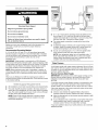
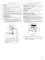
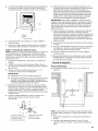
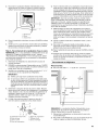
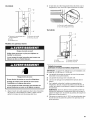
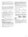
All installations must meet local plumbing code requirements.
The water shutoff should be located in the base cabinet on
either side of the refrigerator or some other easily accessible
area. The water supply line, however, must come up through
the floor in the gray shaded area shown.
NOTE: There is not enough clearance to achieve a flush
installation if a water shutoff valve is located in the wall
behind the refrigerator.
6"
(15.2 cm)
+
1" ,_ 6""
(2.54 cm) (15.2 c
• A 1/2"(12.7 mm) hole for plumbing should be drilled on the
floor at least 6" (15.2 cm) from the right or left hand side
cabinet and should be no more than 1" (2.54 cm) away from
the back wall. See "Connect the Water Supply.
• The water supply connection is made at the front of the
refrigerator.
• If additional tubing is needed, use copper tubing and check
for leaks. Install the copper tubing only in areas where the
household temperatures will remain above freezing.
• Do not use a piercing-type or 3/le"(4.76 mm) saddle valve
which reduces water flow and clogs more easily.
NOTE: Your refrigerator dealer has a kit available with a 1/4"
(6.35 mm) saddle-type shutoff valve, a union, and copper
tubing. Before purchasing, make sure a saddle-type valve
complies with your local plumbing codes.
Water Pressure
A cold water supply with water pressure between 30 and 120 psi
(207 and 827 kPa) is required to operate the water dispenser and
ice maker. Ifyou have questions about your water pressure, call a
licensed, qualified plumber.
Reverse Osmosis Water Supply
IMPORTANT: The pressure of the water supply coming out of a
reverse osmosis system going to the water inlet valve of the
refrigerator needs to be between 30 and 120 psi (207 and
827 kPa).
If a reverse osmosis water filtration system is connected to your
cold water supply, the water pressure to the reverse osmosis
system needs to be a minimum of 40 to 60 psi (276 to 414 kPa).
If the water pressure to the reverse osmosis system is less than
40 to 60 psi (276 to 414 kPa):
• Check to see whether the sediment filter in the reverse
osmosis system is blocked. Replace the filter if necessary.
• Allow the storage tank on the reverse osmosis system to refill
after heavy usage.
• If your refrigerator has a water filter, it may further reduce the
water pressure when used in conjunction with a reverse
osmosis system. Remove the water filter cartridge.
If you have questions about your water pressure, call a licensed,
qualified plumber.
8

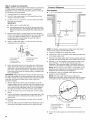
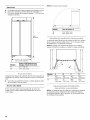
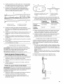
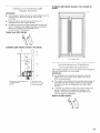
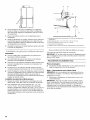
IM PORTANT:
The depth from the front face of the doors to the back of the
refrigerator cabinet is 24" (60.96 cm) without panels.
The power cord is 84" (213 cm) long.
The water supply connection is made at the bottom front of
the refrigerator.
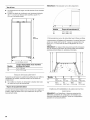
TopView
T
24"
(61.0 cm)
Model A
42 41¾" (106 cm)
48 473/4'' (121.3cm)
Front View
• Width dimensions were measured from hinge to hinge.
• When leveling legs are fully extended to 11/4"(3.2 cm) below
rollers, add 1V4"(3.2 cm) to the height dimensions.
I
*83%"
(211.8 cm)
._L
A
(see chart following)
Model Width A (hinge edge to hinge edge)
42 413/4"(106 cm)
48 473/4'' (121.3 cm)
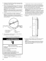
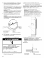
Tqpp ng ky d t s
Be sure there is adequate ceiling height to stand the refrigerator
upright when it is moved into place.
• The dolly wheel height must be added to the tipping radius
when a dolly is used.
Side Tipping Radius
The side tipping radius varies depending upon the width of the
model. Use the chart provided to determine the side tipping
radius.
NOTE: Tip on side only.
!
/
i I
I
1
i/
I
I
I
f
I
/
/
/
/
/
/
s" II
ii ii
Model Tipping Radius A
42 913/8"(232.1 cm)
48 943/8"(239.7 cm)
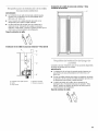
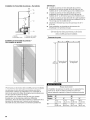
The location must permit both doors to open to a minimum of
90°. Allow 41/2'' (11.4 cm) minimum space between the side of the
refrigerator and a corner wall.
NOTE: More clearance may be required if you are using wood
overlay panels, custom handles, or extended handles.
A B c
I°L\ --- i!\\\
Model A B C D
42 40¾" 39¾" 453/8'' 46¾"
(103.5cm) (101.0cm) (115.3cm) (118.8cm)
48 431/4'' 42" 48%" 501/4''
(109.9 cm) (106.7 cm) (123.5 cm) (127.6 cm)

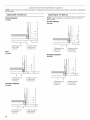
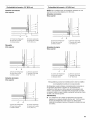
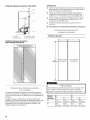
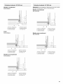
bel cxx:: Op tons
NOTE: Graphics shown below illustrate installation configuration options given the specified cabinet depths. All possible configurations
are not shown.
Cabinet Depth--25" (63.5 cm)
Framed Cabinetry
TopView
F
Inset
TopView
A. Refrigerator door
B. Door panel
C. Side trim
i
B
D. Adjacent cabinet
E. Grille bracket
F. 25" (63.5 cm)
Cabinet Depth--24" (60.9 cm)
NOTE: A flush installation is not possible with a 24" (60.9 cm)
deep opening.
Framed Cabinetry
Top View
A B
A. Refrigerator door
B. Door panel
C. Side trim
D. Adjacent cabinet
E. Grille bracket
F. 24" (60.9 cm)
Frameless Cabinetry
TopView
A B
A. Refrigera tor door
B. Door panel
C. Side trim
Frameless Cabinetry
TopView
D. Adjacent cabinet
E. Grille bracket
F. 25" (63.5 cm)
A B
A. Refrigerator door
B. Door panel
C. Side trim
F
I
D.Adjacent cabinet
E. Grille bracket
F. 24" (60.9 cm)
A B
A. Refrigerator door
B. Door panel
C. Side trim
F
D. Adjacent cabinet
E.Grille bracket
F. 25" (63.5 cm)
10

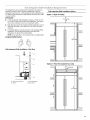
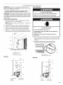
The refrigerator can be installed fully integrated if the adjacent
cabinetry meets the airflow venting requirements critical to
refrigerator performance. A Fully Integrated Grille installation has
no visible air gap because the grille extends upward to the soffit
or upper cabinet.
IM PORTANT:
6" (15,24 cm)
• A Fully Integrated Grille installation requires a minimum of 6" min.
(15.24 cm) of open space above the refrigerator. This space ,I,
must not be blocked in any way, including by soffits.
Y
• Both Standard and Fully Integrated Grille installations can be
achieved with either a 24" (60.9 cm) or 25" (63.5 cm) deep
opening.
• A full height grille is used to achieve a Fully Integrated Grille
installation. Use the integrated bracket (provided with
refrigerator) to attach the full height grille.
NOTE: A top grille filler is not required with a full height grille.
Integrated Grille Bracket
Fully Integrated Grille Installation--Side View
Fully Integrated Grille Installation Options
Option 1--Open to Ceiling
84"
(213.4 cm)
ri
A. False front (optional)
B. Airflow
C
C. Full height grille
D. Doorpanel
Option 2-False Front (cabinet face only)
0
6" (15.24 cm)
mln,
111,
84"
(213.4 cm)
11

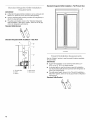
IMPORTANT:
• A Standard Integrated Grille installation can be achieved with
either a 24" (60.9 cm) or 25" (63.5 cm) deep opening.
• Use the standard grille bracket (provided with refrigerator) to
attach the standard grille.
• The grille panel height, shown inthe "Standard Integrated
Grille Installation--Side View" graphic, allows for an air gap
critical to refrigerator performance.
Standard Grille Bracket
Standard Integrated Grille Installation--Side View
A
..................B
I I
Standard Integrated Grille Installation--Full Product View
........ C
C. Airflow
A. Top grille filler D. Grille panel
B. Soffit E. Door panel
C. Airflow
See the "Models" section to see the panel kit options available
for your model.
IM PORTANI"."
• A panel kit installation can be achieved with either a 24"
(60.9 cm) or 25" (63.5 cm) deep opening.
• A standard grille is used to achieve a panel kit installation.
Use the standard grille bracket (provided with refrigerator) to
attach the standard grille.
• The grille panel height, shown in the "Panel Kit Installation--
Side View" graphic, allows for an air gap critical to refrigerator
performance.
Standard Grille Bracket
12

• The weight of the top grille wood overlay panel cannot
exceed 8 Ibs (3.6 kg) for 48=models or 7 Ibs (3.2 kg) for 42=
models.
• The required thickness for all panels is 3/4"(1.91 cm).
• This installation does not require filler or backer panels.
Door Panels
A. Soffit C. Grillepanel
B.Airflow D.Door panel
Panel Kit Installation-- Full Product View
Custom wood overlay panels allow you to blend the exterior of
your refrigerator into the overall kitchen decor, and to use custom
handles for additional design flexibility.
In some cases, your cabinet manufacturer may choose to work
with one panel routed for the different dimensions. Follow these
panel dimension and placement instructions to be sure that the
custom wood overlay panels will fit properly.
IM PORTANT:
• The weight of the refrigerator door wood overlay panel
cannot exceed 66 Ibs (29.9 kg) for 48 =models or 65 Ibs
(29.5 kg) for 42 =models.
• The weight of the freezer door wood overlay panel cannot
exceed 50 Ibs (23 kg) for 48 =models or 49 Ibs (22.2 kg) for
42 =models.
741/4"
(188.6 cm)
Freezer
Door Panel
Refrigerator
Door Panel
Pinch Hazard
Installation of door panels with less than a 3/8"(0.95 cm) gap
between the door panel and the adjacent cabinet increases
the risk of potential pinching.
Model 42 48
Reveal %" 1/&,, 3/8,, W'
A 179/le'' 1713/16'' 201/le'' 208/1e''
(44.61 cm) (45.24 cm) (50.96 cm) (51.59 cm)
B 23e/16'' 2313/16'' 271/16'' 278/16''
(59.85 cm) (60.48 cm) (68.74 cm) (69.37 cm)
Grille Panel
Fully Integrated Grille Installation-- Full Height Grille--
Open Soffit
_{ C )'1
Model 42 48
Reveal 3/8" W' %" W'
C 411/4" 413/4" 471/4'' 473/4''
(104.78cm) (106.05cm) (120.02 cm) (121.29cm)
13

Standard Grille Installation--Flush Grille--Open or Closed
Soffit
I-' D "1
1"(2.54cm)I TopGrilleFiller I
I" E '-I
53/4" t
Model 42 48
Reveal 3/8" 1/8" 3/8" 1/8"
D 411/4" 41%" 471/4" 47%"
(104.78 cm) (106.05 cm) (120.02 cm) (121.29 cm)
E 411/4" 41%" 471/4'' 47%"
(104.78 cm) (106.05 cm) (120.02 cm) (121.29 cm)
IMPORTANT: The grille panel height, shown in the "Standard
Integrated Grille Installation--Side View" graphic, allows for an air
gap critical to refrigerator performance.
INSTALLATIONINSTRUCTIONS
Tip Over Hazard
Refrigerator is top heavy and tips easily when not
completely installed.
Keep doors taped closed until refrigerator is
completely installed.
Use two or more people to move and install
refrigerator.
Failure to do so can result in death or serious injury.
IMPORTANT:
• Do not remove the film covering until the refrigerator is in its
operating location.
• All four leveling legs must contact the floor to support and
stabilize the full weight of the refrigerator.
• Keep the cardboard shipping piece or plywood under the
refrigerator until it is installed in the operating location.
1. Remove and save the literature package and hardware kit
located inside the refrigerator. Remove and save the
literature, grille, and trim taped to the outside of the
refrigerator.
NOTE: Do not remove tape and door bracing until the
refrigerator is in its final location.
Move ;'he
Tip Over Hazard
Refrigerator is top heavy and tips easily when not
completely installed.
Keep doors taped closed until refrigerator is
completely installed.
Use two or more people to move and install
refrigerator.
Failure to do so can result in death or serious injury.
1=
Place an appliance dolly under the left side of the refrigerator
as shown. Place the corner posts from the packing materials
over the trims as appropriate. Slowly tighten the strap.
2. Place pieces of the shipping carton on the floor when rolling
the dolly and refrigerator into the house. Move the refrigerator
close to the built-in opening.
3. Place top of cardboard carton or plywood under refrigerator.
4. Stand the refrigerator up. First, place the left bottom edge of
the refrigerator on the floor, stand the refrigerator upright and
then lower the right-hand side of the refrigerator to the floor.
5. Reassemble the trim and top grille after the dolly has been
removed from the refrigerator.
14

A' t,,:R© Bo<:; ds
IMPORTANT:
• If a solid soffit is not available, an anti-tip board must be
installed.
• It is recommended that board(s) be installed before the
refrigerator is installed.
• Board(s) must be long enough to fully cover the width of the
compressor cover.
• Locate the board(s) so the bottom surface(s) of the board(s)
is(are) 84" (213 cm) from the floor.
• During installation, raise the refrigerator up until the top of the
refrigerator is making contact with the bottom of the anti-tip
board(s). Do not crush the compressor cover when raising the
rear leveling legs.
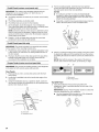
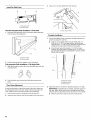
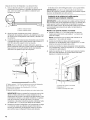
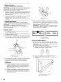
To Install Anti-tip Boards
1. Mark the stud locations on rear wall 80" to 90" (203 cm to
229 cm) above floor.
2. Securely attach one or two 2" x 4" x 32" (5 cm x 10 cm x
81 cm) boards to wall studs behind refrigerator. Use six
#8 x 3" (7.6 cm) (or longer) wood screws. The wood screws
must be screwed into the studs at least 11/2"(3.8 cm). The
board(s) must overlap the compressor cover.
A B
2" (5 cm)
• I
D
...... C
_?_"1/4"(6 ram)
max.
84 II
(213.4 cm)
A. Center board _" (6.35 mm) max. above refrigerator
B. Two 2" x 4" x 32" (5 cm x 10 cm x 81 cm) boards
C. Attach to studs with six #8 x 3" (7.6 cm) screws
D. Compressor cover
E.Distance from bottom of anti-tip board to floor
Read all directions before you begin.
IMPORTANT: Ifyou turn the refrigerator on before the water line
is connected, turn the ice maker OFE
Connect to Water Line
Parts Needed:
• Minimum 7 ft (2.13 m)flexible, codes approved water
supply line
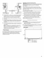
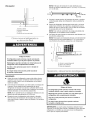
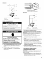
Style 1--Shutoff Valve Connection
NOTE: If your water line connection does not look like Style 1,
see "Style 2--Copper Line Connection."
1. Unplug refrigerator or disconnect power supply.
IMPORTANT: Before attaching the tubing to shutoff valve, flush
the main water supply line to remove particles and air in the water
line. Allow enough flow so that water becomes clear. Flushing the
water line may help avoid filters and/or water valves from
becoming clogged.
2. Connect the flexible, codes approved water supply line to the
water shutoff valve by threading the provided nut onto the
shutoff valve as shown.
A
I1 II
B
C
A. Bulb
B. Nut
C. Water tubing
3. Place the end of the tubing into a bucket, and turn shutoff
valve ON.
4. Check for leaks. Tighten any nuts or connections (including
connections at the valve) that leak.
15

Style 2--Copper Line Connection
NOTE: If there is a water supply line that meets the specifications
in "Water Supply Requirements," proceed to "Connecting to
Refrigerator." If not, use the following instructions to connect to
the household cold water supply.
1. Unplug refrigerator or disconnect power.
2. Turn OFF main water supply. Turn ON nearest faucet long
enough to clear line of water.
3. Locate a 1/2"to 11/4'' (1.25 cm to 3.18 cm) vertical cold water
pipe near the refrigerator.
IMPORTANT:
• Make sure it is a cold water pipe.
• Horizontal pipe will work, but drill on the top side of the
pipe, not the bottom. This will help keep water away from
the drill and keep normal sediment from collecting in the
valve.
4. Determine the length of copper tubing you need. Measure
from the connection on the refrigerator to the water pipe. Add
7 ft (2.1 m) to allow for cleaning. Use 1/4"(6.35 mm) O.D.
(outside diameter) copper tubing. Be sure both ends of
copper tubing are cut square.
5. Using a cordless drill, drill a 1/4"(6.35 mm) hole in the cold
water pipe you have selected.
A. Cold water pipe E. Compression sleeve
B.Pipe clamp R Shutoff valve
C. Copper tubing G.Packing nut
D. Compressionnut
6. Fasten the shutoff valve to the cold water pipe with the pipe
clamp. Be sure the outlet end is solidly in the 1/4"(6.35 mm)
drilled hole in the water pipe and that the washer is under the
pipe clamp. Tighten the packing nut. Tighten the pipe clamp
screws slowly and evenly so washer makes a watertight seal.
Do not overtighten.
IMPORTANT: Before attaching the tubing to shutoff valve, flush
the main water supply line to remove particles and air in the water
line. Allow enough flow so that water becomes clear. Flushing the
water line may help avoid filters and/or water valves from
becoming clogged.
7. Slip the compression sleeve and compression nut on the
copper tubing as shown. Insert the end of the tubing into the
outlet end squarely as far as it will go. Screw compression nut
onto outlet end with adjustable wrench. Do not overtighten
the clamp or the sleeve. This will crush the copper tubing.
8. Turn off the shutoff valve on the water pipe. Coil the copper
tubing.
9. Connect the flexible, codes approved water supply line to the
water shutoff valve by threading the provided nut onto the
shutoff valve.
10. Place the end of the tubing into a bucket, and turn shutoff
valve ON.
11. Check for leaks around the saddle valve. Tighten any nuts or
connections (including connections at the valve) that leak.
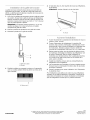
Connect to Refrigerator
Parts Supplied:
• 1/4"to 1/4"(6.35mm to 6.35 mm) male-to-male coupling
{I
tI
{I
tI
6 II
(15.2 cm) I
I (17.78 cm)
NOTE: The flexible, codes approved water supply line should
connect to the supply valve through the floor.
1. Unplug the refrigerator or disconnect power.
2. Connect the 7 ft (2.13 m) flexible codes approved water tube
to the water supply valve.
3. Flush the main water supply line to remove particles and air in
the water line. Allow enough flow so that water becomes clear.
4. Tape the 7 ft (2.13 m) flexible codes approved water supply
line to the floor, 7" (17.78 cm) from the left side of the
refrigerator. Tape along the length of the tubing, which will
allow it to pass beneath the refrigerator without interference.
NOTE: Allow a minimum of 26" (66.04 cm) of flexible codes
approved water supply line to be loose at the front of the
refrigerator for connecting to the refrigerator.
5. Connect the 7 ft (2.13 m) flexible codes approved water
supply line to the refrigerator.
NOTE: If the main water shutoff valve is behind the
refrigerator, a secondary water shutoff valve may be installed
in line with the water supply line at the front of the 3roduct.
A. Household water line E. Bulb
B. Nut (purchased) R Nut
C. Ferrule (purchased) G. Refrigerator water tubing
D. Coupfing
6. Turn on the water supply valve and check all connections for
leaks.
16

Electrical Shock Hazard
Plug into a grounded 3 prong outlet.
Do not remove ground prong.
Do not use an adapter.
Do not use an extension cord.
Failure to follow these instructions can resuR in death,
fire, or electrical shock.
1. Set control switch at top of cabinet to the OFF position.
2. Plug into a grounded 3 prong outlet.
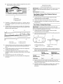
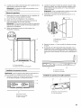
n Sd® ms
The side trims cover the space between the refrigerator and the
adjacent cabinets. There is a trim piece taped to each side of the
refrigerator. Install each trim piece to the side of the refrigerator to
which it is taped.
1. Remove the tape attaching the trim pieces to the sides of the
refrigerator. Set the trim pieces aside.
IMPORTANT: For installations using custom wood panels
with 1/8"gap, the bulb-shaped section of the trim piece will
interfere with the panels. Score each trim piece at the base of
the bulb-shaped section, then remove and discard this
section. See the "Top View" graphic later in this section.
2. Remove the 4 screws from the side of the refrigerator cabinet.
3. Using the original holes and the screws removed in Step 2,
fasten the side trim to the refrigerator cabinet.
NOTE: Make sure to fasten each trim piece to the side of the
refrigerator cabinet from which it was removed. The bulb-
shaped section should be forward with the notch at the top,
as shown.
Top View
C
A. Side trim C. Door
B.Adjacent cabinet D. Bulb-shaped section
Tip Over Hazard
Refrigerator is top heavy and tips easily when not
completely installed.
Keep doors taped closed until refrigerator is
completely installed.
Use two or more people to move and install
refrigerator.
Failure to do so can result in death or serious injury.
IM PORTANI"."
• To avoid floor damage, make sure levelers are raised (not
touching floor) and refrigerator is on rollers before moving.
• Use the installation block, attached to the door hinge, as a
reference to make sure the refrigerator is pushed back far
enough into the opening, so that when the panels are
installed they will be flush with the adjacent cabinets.
NOTE: A flush installation is not possible with a24" (60.9 cm)
deep opening.
A. Side trim screws
17

After the refrigerator is leveled and aligned, remove the
installation block from the door hinge and use it to check the
spacing between the panels and adjacent cabinets.
NOTE: The installation block is designed to provide accurate
spacing for 3/4"(1.9 cm), 3/8"(9.53 mm) and 1/8"(3.18 mm).
3/4,,
(1.9 cm)
i ,/8,,
_ (3.18 mm)
(9.53 mm)
1. Place top of cardboard carton or plywood under refrigerator.
Remove dolly.
2. Move the refrigerator straight back and evenly into the
opening. Be sure that the water tubing is not kinked and the
power supply cord is on top of the refrigerator.
NOTE: If the power supply cord is behind the refrigerator, it
will not install properly.
3. Make sure the installation block is flush with the adjacent
cabinets.
NOTE: To achieve a flush installation, it is critical to verify a
3/4"(1.9 cm) depth from the front face of the adjacent
cabinetry to the refrigerator.
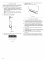
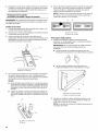
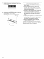
After moving the refrigerator to its final location:
1. Use a _e" socket driver to turn the leveling bolts clockwise to
extend the legs to the floor as shown. The rollers should be
off the floor.
A. Rear leveling bolt
B. Front leveling bolt
2.
3.
Adjust the leveling legs to level and align the refrigerator from
left to right and front to back so that the refrigerator is level
and aligned with the cabinets.
Continue adjusting all of the leveling legs to raise the
refrigerator until the top is within at least 1/4"(6.35 mm) of the
top soffit as shown.
NOTE: If an anti-tip board has been used, adjust the leveling
legs until the top of the refrigerator is making contact with the
bottom of the anti-tip board(s). Do not crush the compressor
cover.
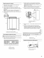
A B
s/4"(1.9 cm)
C ....
A. Adjacent cabinet or wall
B. Instaflation block
C. Face of refrigerator
Tip Over Hazard
Refrigerator is top heavy and tips easily when not
completely installed.
Keep doors taped closed until refrigerator is
completely installed.
Use two or more people to move and install
refrigerator.
Failure to do so can result in death or serious injury.
IMPORTANT: All four leveling legs must contact the floor to
support and stabilize the full weight of refrigerator. Rollers are for
moving the refrigerator, not for permanent support.
4,
2" (5 cm)
\
,_................C
_q/4"(6mm)
max.
84 ,I
(213.4 cm)
D
E
A. Center board _" (6.35 mm) max. above refrigerator
B. Two 2" x 4" x 32" (5 cm x 10 cm x 81 cm) boards
C. Attach to studs with six #8 x 3" (7.6 cm) screws
D. Compressor cover
E. Distance from bottom of anti-tip board to floor
IMPORTANT: Adjust in small increments to keep from
damaging the cabinet trim and causing problems with the
door alignment or top grille fit. To avoid damage to the
cabinet or leveling legs, do not apply more than 50 inch-
pounds (5.65 Nm) of torque to the leveling bolts. The leveling
legs can be extended to a maximum of 11/4'' (3.18 cm) below
the rollers.
After leveling the refrigerator, again use a straight edge or 4-ft
level across the front of the refrigerator installation blocks to
the cabinets to check that the refrigerator is still flush.
18

IMPORTANT: Jenn-Air is not responsible for the removal or
addition of molding or wood overlay panels that would not allow
access to the refrigerator for service.
Install Top Grille Filler (standard installation only)
IMPORTANT: The grille panel height allows the necessary airflow
for refrigerator performance. The top grille filler hides the upper
compartment cover behind the top grille. If you choose to modify
the recommended grille panel dimensions, performance will be
compromised.
Custom Wood Panel Models
1. In the custom made (1" x width of grille panel) wood filler
piece, drill a hole 11_6"from each edge.
NOTE: Make sure the hole is centered in the 1" thickness of
the wood piece.
2. Using slotted hex-head screws (provided with refrigerator),
fasten an "L" bracket to each end of the wood filler piece.
3. Using hex-head blunt screws (provided with refrigerator),
attach the "L" brackets to the top grille mounting plates.
4. Adjust the "L" brackets, so that the wood filler piece is flush
with the bottom of the soffit. Completely tighten the screws.
A
B
Side View
A. Custom wood rifler
B. "L" bracket
C. Grille mounting plate
A
Panel Kit Models
Excessive Weight Hazard
Use two or more people to move and install panels.
Failure to do so can result in back or other injury.
Broken Glass Hazard
Do not hit refrigerator glass doors.
Protect glass surface and edges during installation or
removal of doors.
Failure to do so can result in serious eye injury or
minor cuts.
1. Align top grille vent (provided in the door kit) with the bottom
edge of the soffit. Use as a template, and mark where to drill
the holes.
2. Using the slotted hex-head screws (provided with
refrigerator), attach the top grille vent to the soffit.
Side View
A. Top grille vent
B. Slotted hex-head screw
A
B
A. Top grille filler D. Grille panel
B. Soffit E. Door panel
C. Airflow
A. Soffit C. Grille panel
B. Airflow D. Door panel
19

Predrill Panels (custom wood panels only)
IMPORTANT: The custom panel template shipped with the
refrigerator can be used for either a 3/8"(0.95 cm) or a 1/8"
(0.32 cm) reveal installation.
• The drilling templates are used only for custom wood overlay
panels.
• The drilling templates are double-sided.
• The drilling holes are precut into the template.
1. On the template, locate the diagram of your refrigerator.
Then, follow the letters and colored arrows to correctly place
the drilling template on the back side panels.
NOTE: Check the direction of the arrows to determine which
holes to mark when the template is aligned at the top of the
panel and which holes to mark when the template is aligned
at the bottom of the panel.
2. Predrill 1/8"(0.32 cm) deep pilot holes into the wood rails
bordering the doors and top grille panels.
Predrill Panels (panel kits only)
IMPORTANT: The panels included in the panel kits are marked
for the location of the mounting brackets only.
1. Predrill holes where marked. See "Complete Installation" later
in this section, for instructions on drilling additional holes in
the door panels.
2. Peel back the film cover on the door panel in the area of the
brackets and handle studs. Do not fully remove the film
covering until the installation is complete.
Prepare Panels (custom wood and panel kits)
IMPORTANT: The process for installing panels on the refrigerator
is the same for both custom panels and panel kits.
Door Panels
1. Place panels on a firm, covered, flat surface with the front
facing down.
2. Locate the 2 predrilled holes in the handle side edge of the
door panel.
3. Using the installation block as a guide for depth, screw the
door studs (provided with refrigerator) into the predrilled door
panel (2 door studs per door).
4=
5=
For the mounting bracket, insert the hex-head pointed
screws (provided with refrigerator) into the wood at the top of
the door panels where they were predrilled.
NOTES:
It is critical to use the %" screw, the longest length
provided, to attach the bracket to the top of the door
panel. These hex-head pointed screws are used only to
attach this mounting bracket.
• Panel Kits--Insert the hex-head pointed screws into the
slots in the door panel, not the U-shaped holes.
A
A. U-shapped hole
B. Slot
Attach a mounting bracket to the top edge of each door panel
by placing the large end of the keyhole slot over the screws
and sliding the bracket so that the screws are centered in the
slots.
NOTE: Start with the screws in the center of the slots as
shown, then move the door panel, as necessary, to align.
A B
/
A. Door panel
B. Mounting bracket
Top Grille Panel
1. Using the slotted hex-head screws (provided with
refrigerator), attach a mounting bracket to each side of the
top grille panel.
IMPORTANT: See the "Parts Provided" section to select the
brackets designated for your installation.
• Use the Integrated Grille brackets for a Fully Integrated
Grille installation with a full height grille.
A. Door stud
B.Installation block
2O
La page est en cours de chargement...
La page est en cours de chargement...
La page est en cours de chargement...
La page est en cours de chargement...
La page est en cours de chargement...
La page est en cours de chargement...
La page est en cours de chargement...
La page est en cours de chargement...
La page est en cours de chargement...
La page est en cours de chargement...
La page est en cours de chargement...
La page est en cours de chargement...
La page est en cours de chargement...
La page est en cours de chargement...
La page est en cours de chargement...
La page est en cours de chargement...
La page est en cours de chargement...
La page est en cours de chargement...
La page est en cours de chargement...
La page est en cours de chargement...
La page est en cours de chargement...
La page est en cours de chargement...
La page est en cours de chargement...
La page est en cours de chargement...
La page est en cours de chargement...
La page est en cours de chargement...
La page est en cours de chargement...
La page est en cours de chargement...
La page est en cours de chargement...
La page est en cours de chargement...
La page est en cours de chargement...
La page est en cours de chargement...
La page est en cours de chargement...
La page est en cours de chargement...
La page est en cours de chargement...
La page est en cours de chargement...
La page est en cours de chargement...
La page est en cours de chargement...
La page est en cours de chargement...
La page est en cours de chargement...
La page est en cours de chargement...
La page est en cours de chargement...
La page est en cours de chargement...
La page est en cours de chargement...
La page est en cours de chargement...
La page est en cours de chargement...
La page est en cours de chargement...
La page est en cours de chargement...
La page est en cours de chargement...
La page est en cours de chargement...
La page est en cours de chargement...
La page est en cours de chargement...
-
 1
1
-
 2
2
-
 3
3
-
 4
4
-
 5
5
-
 6
6
-
 7
7
-
 8
8
-
 9
9
-
 10
10
-
 11
11
-
 12
12
-
 13
13
-
 14
14
-
 15
15
-
 16
16
-
 17
17
-
 18
18
-
 19
19
-
 20
20
-
 21
21
-
 22
22
-
 23
23
-
 24
24
-
 25
25
-
 26
26
-
 27
27
-
 28
28
-
 29
29
-
 30
30
-
 31
31
-
 32
32
-
 33
33
-
 34
34
-
 35
35
-
 36
36
-
 37
37
-
 38
38
-
 39
39
-
 40
40
-
 41
41
-
 42
42
-
 43
43
-
 44
44
-
 45
45
-
 46
46
-
 47
47
-
 48
48
-
 49
49
-
 50
50
-
 51
51
-
 52
52
-
 53
53
-
 54
54
-
 55
55
-
 56
56
-
 57
57
-
 58
58
-
 59
59
-
 60
60
-
 61
61
-
 62
62
-
 63
63
-
 64
64
-
 65
65
-
 66
66
-
 67
67
-
 68
68
-
 69
69
-
 70
70
-
 71
71
-
 72
72


Jenn-Air JS48NXFXDW01 Guide d'installation
- Catégorie
- Frigos
- Taper
- Guide d'installation
- Ce manuel convient également à
dans d''autres langues
Documents connexes
-
Jenn-Air JS42NXFXDW Guide d'installation
-
Jenn-Air JS48NXFXDW Manuel utilisateur
-
Jenn-Air JF36NXFXDE Guide d'installation
-
-
-
-
-
Jenn-Air JPK36BNXWES Guide d'installation
-
-
