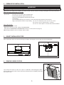
Best WCB3I30SBN Guide d'installation
- Catégorie
- Hottes
- Taper
- Guide d'installation

WCB3I SERIES
HB0046
INSTALLATION INSTRUCTIONS
INTENDED FOR DOMESTIC COOKING ONLY
INSTALLER: LEAVE THIS MANUAL WITH HOMEOWNER.
HOMEOWNER: USE AND CARE INFORMATION ON PAGES 12 AND 13.
READ AND SAVE THESE INSTRUCTIONS
BEST; Hartford, Wisconsin www.BestRangeHoods.com 800-558-1711
BEST; Drummondville, QC, Canada www.BestRangeHoods.ca 866-737-7770
23865 rev. 03
! !

2
TO REDUCE THE RISK OF FIRE, ELECTRIC SHOCK OR
INJURY TO PERSONS, OBSERVE THE FOLLOWING:
1. Use this unit only in the manner intended by the manufacturer.
If you have questions, contact the manufacturer at the address
or telephone number listed in the warranty.
2. Before servicing or cleaning unit, switch power off at service
panel and lock service disconnecting means to prevent
power from being switched on accidentally. When the service
disconnecting means cannot be locked, securely fasten a
prominent warning device, such as a tag, to the service panel.
3. Installation work and electrical wiring must be done by
qualified personnel in accordance with all applicable codes
and standards, including fire-rated construction codes and
standards.
4. Sufficient air is needed for proper combustion and exhausting
of gases through the flue (chimney) of fuel burning equipment
to prevent backdrafting. Follow the heating equipment
manufacturer’s guidelines and safety standards such as
those published by the National Fire Protection Association
(NFPA) and the American Society for Heating, Refrigeration
and Air Conditioning Engineers (ASHRAE) and the local code
authorities.
5. When cutting or drilling into wall or ceiling, do not damage
electrical wiring and other hidden utilities.
6. Ducted fans must always be vented outdoors.
7. Do not use this unit with any solid-state speed control device.
8. To reduce the risk of fire, use only metal ductwork.
9. This unit must be grounded.
10. All tempered glass can experience spontaneous breakage. If
broken, tempered glass falls out of its opening in interlocking
clumps. Tempered glass can, on occasion, break into large
shards rather than the classic tiny piece pattern.
11. When applicable, local regulations comprise more
restrictive installation and/or certification requirements,
the aforementioned requirements prevail on those of this
document and the installer agrees to conform to these at his
own expense.
TO REDUCE THE RISK OF A RANGE TOP GREASE FIRE:
a) Never leave surface units unattended at high settings. Boilovers
cause smoking and greasy spillovers that may ignite. Heat oils
slowly on low or medium settings.
b) Always turn power hood ON when cooking at high heat or
when flambeing food (i.e.: Crêpes Suzette, Cherries Jubilee,
Peppercorn Beef Flambé).
c) Clean ventilating fans frequently. Grease should not be allowed
to accumulate on fan, filters or in exhaust ducts.
d) Use proper pan size. Always use cookware appropriate for the
size of the surface element.
1. For indoor use only.
2. For general ventilating use only. Do not use to exhaust
hazardous or explosive materials and vapors.
3. To avoid motor bearing damage and noisy and/or unbalanced
impellers, keep drywall spray, construction dust, etc. off power
unit.
4. Your hood motor has a thermal overload which will automatically
shut off the motor if it overheats. The motor will restart when it
cools down. If the motor continues to shut off and restart, have
the hood serviced.
5. The minimum hood distance above cooktop must not be
less than 24” (30” over a gas range). A maximum of 30”
above cooktop is recommended for best capture of cooking
impurities.
6. Two installers are recommended because of the large size and
weight of this unit.
7. To reduce the risk of fire and to properly exhaust air, be sure to
duct air outside — Do not exhaust air into spaces within walls
or ceiling or into attics, crawl space or garage.
8. Because of the high exhausting capacity of this hood, you
should make sure enough air is entering the house. Open a
window close to or in the kitchen.
9. To reduce the risk of fire and electrical shock, the Best WCB3I
Series models should only be installed with its own built-in
blower.
10. Please read specification label on product for further
information and requirements.
WARNING
!
CAUTION
TO REDUCE THE RISK OF INJURY TO PERSONS IN THE
EVENT OF A RANGE TOP GREASE FIRE, OBSERVE
THE FOLLOWING*:
1. SMOTHER FLAMES with a close-fitting lid, cookie sheet or
metal tray, then turn off the burner. BE CAREFUL TO PREVENT
BURNS. IF THE FLAMES DO NOT GO OUT IMMEDIATELY,
EVACUATE AND CALL THE FIRE DEPARTMENT.
2. NEVER PICK UP A FLAMING PAN — You may be burned.
3. DO NOT USE WATER, including wet dishcloths or towels —
This could cause a violent steam explosion.
4. Use an extinguisher ONLY if:
A. You own a Class ABC extinguisher and you know how to
operate it.
B. The fire is small and contained in the area where it started.
C. The fire department has been called.
D. You can fight the fire with your back to an exit.
* Based on “Kitchen Fire Safety Tips” published by NFPA.
WARNING
!

3
HL0226
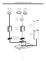
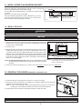
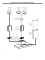
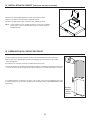
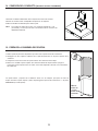
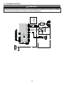
WCB3I SERIES RANGE HOOD SYSTEM
MODEL 639
(3¼" X 10"
WALL CAP)
MODEL 634
OR 644
(ROOF CAP)
MODEL 639
(3¼" X 10"
WALL CAP)
(O
PTIONAL
3¼"
X 10"
ELBOW)
(3¼" X 10"
STANDARD
DUCT)
ADAPTER/DAMPER 3¼" X 10"
(SUPPLIED WITH HOOD)
FOR HORIZONTAL OR VERTICAL
DISCHARGE
UPPER
DECORATIVE
FLUE
LOWER
DECORATIVE
FLUE

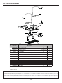
4
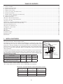
TABLE OF CONTENTS
1. I NSTALL DUCTWORK ................................................................................................................................................................4
2. PREPARE THE INSTALLATION .....................................................................................................................................................5
3. SELECT INSTALLATION TYPE .....................................................................................................................................................5
4. R
EMOVE HYBRID FILTERS ........................................................................................................................................................5
5. INSTALL GLASS PANEL (SBN MODELS ONLY) .................................................................................................................................6
6. PREPARE THE OPENING ..........................................................................................................................................................6
7. B LOWER REMOVAL (HORIZONTAL DISCHARGE ONLY) ......................................................................................................................7
8. INSTALL THE ADAPTER/DAMPER .................................................................................................................................................7
9. WIRING INSTALLATION .............................................................................................................................................................8
10. INSTALL HOOD MOUNTING BRACKET ...........................................................................................................................................8
11. INSTALL UPPER FLUE MOUNTING BRACKET ...................................................................................................................................9
12. INSTALL THE HOOD .................................................................................................................................................................9
13. REINSTALL THE BLOWER (HORIZONTAL DISCHARGE ONLY) ............................................................................................................... 9
14. DUCT CONNECTION (VERTICAL DISCHARGE ONLY) ....................................................................................................................... 10
15. PREPARE DECORATIVE FLUE ...................................................................................................................................................10
16. INSTALL THE DECORATIVE FLUE ............................................................................................................................................... 11
17. REINSTALL HYBRID FILTERS .................................................................................................................................................... 11
18. LED LIGHTING ....................................................................................................................................................................12
19. CARE ................................................................................................................................................................................12
20. OPERATION ........................................................................................................................................................................13
21. WIRING DIAGRAM.................................................................................................................................................................14
22. SERVICE PART S ...................................................................................................................................................................15
23. WARRANTY ........................................................................................................................................................................16
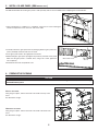
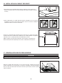
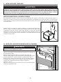
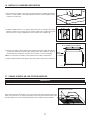
Plan where and how the ductwork will be installed.
The ducting from this fan to the outside of the building has a strong effect on the airflow,
noise and energy use of the fan. Use the shortest, straightest duct routing possible for best
performance, and avoid installing the fan with smaller ducts than recommended. Insulation
around the ducts can reduce energy loss and inhibit mold growth. Fans installed with existing
ducts may not achieve their rated airflow. Refer to the table below to help you plan the most
efficient installation.
Install wall or roof cap and ensure there is no leak in house insulation. Connect metal ductwork
to cap and work back towards the hood location. Use 2” metal foil duct tape to seal the joints.
We recommend to install the hood at a minimum distance of 24” from an electric range
and of 30” from a gas range.
Distances over 36 in. are at the installer and users discretion.
*10-ft. ceilings require 10-ft. flue extension, part no. AEWCB3SB (sold separately).
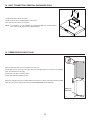
1. INSTALL DUCTWORK
3¼” X 10” DUCT
R
OOF CAP
3¼” X 10”
DUCT
HOOD
DECORATIVE
FLUE
HH0221A
24" MINIMUM ABOVE
COOKING SURFACE
(30" FOR GAS RANGE)
3¼” X 10”
ADAPTER/DAMPER
WALL
CAP
3¼” X 10”
ADAPTER/DAMPER
CEILING HEIGHT 8 FEET 9 FEET 10 FEET*
M
INIMUM/MAXIMUM DISTANCE RECOMMENDED
ABOVE COOKTOP FOR ELECTRIC RANGE
24 IN./30 IN. 24 IN./30 IN. 24 IN./30 IN.
M
INIMUM/MAXIMUM DISTANCE RECOMMENDED
ABOVE COOKTOP FOR GAS RANGE
30 IN./33 IN. 30 IN./36 IN. 30 IN./36 IN.
3¼ IN. X 10 IN.
M
AXIMUM DUCT LENGTH
ROOF OR WALL CAP
WITH DAMPER
ELBOW(S)*
(90°
AND/OR 45°)
60
FT.1 0
50
FT.1 1
40
FT.1 2
M
AXIMUM DUCT LENGTH RECOMMENDED TO ACHIEVE 80% EXHAUST EFFICIENCY
*STANDARD ELBOWS WITH 1” INTERNAL RADIUS.

5
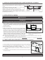
2. PREPARE THE INSTALLATION
NOTE: Before proceeding to the installation, check the contents of the box. If items are missing or damaged, contact the manufacturer.
Make sure that the following items are included:
- Hood
- Accessories • Decorative flue assembly (lower and upper flues)
• Hood mounting bracket (taped inside the hood)
• Upper flue mounting bracket (taped inside the hood)
• 2 hybrid filters
• 3¼” x 10” adapter/damper (for horizontal or vertical discharge) taped inside the decorative flue
• Bag of parts (taped inside the hood) including: 5 no. 8 x 1½” countersunk screws, 8 no. 8 x 3/4” screws,
6 no. 8 x 3/8” screws, 6 drywall anchors, 3 washers,
2 no. 8 x 1/2”, 2 foam squares. If need be, discard extra hardware.
Parts sold separately:
- Duct, elbows, wall or roof caps.
- Optional flue extension for 10-ft. ceilings model AEWCB3SB.
- Glass panel for WCB3I30SBN and WCB3I36SBN models (see service parts list on page 15).
NOTE: During installation, protect countertop and/or cooktop.
WARNING
!
When performing installation, servicing or cleaning the unit, it is recommended to wear safety glasses and gloves.
HK0059A
C
L
9¾”
3
3
⁄16”
11
”
1
5
⁄8”
14
15
⁄16”
17
15
⁄16”
36” WIDTH HOOD
30” WIDTH HOOD
HORIZONTAL DISCHARGE
HK0060A
C
L
9¾”
7/8”
14
15
⁄16”
17
15
⁄16”
36” WIDTH HOOD
30” WIDTH HOOD
3
3
⁄16”
VERTICAL DISCHARGE
3. SELECT INSTALLATION TYPE
Refer to illustrations below to locate duct opening according to discharge type chosen (grey parts to be installed later).
4. REMOVE HYBRID FILTERS
Lay the back of the hood on a table. Use a piece of cardboard to avoid damaging the table or
the hood. Remove tape on filters. Remove filters by pushing them down and flipping downwards.
Set the filters aside.
HO0250

6
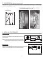
5. INSTALL GLASS PANEL (SBN MODELS ONLY)
The SBN hood models decorative glass panel is sold separately and has to be installed before completing the hood installation.
1. Using a Robertson or a Phillips no. 2 screwdriver, remove the 5 screws retaining the
electrical compartment cover. Set cover and screws aside.
HD0560
SCREW LOCATIONS
2. Carefully remove the glass panel from its packaging. Remove glass panel nuts
(factory installed) from both studs and set aside.
3. Insert glass panel studs in the appropriate hood holes.
4. While holding the glass panel, pre-tighten the previously removed nuts by hand.
Make sure the glass panel is centered. Then, using a 3/8" socket, tighten the
nuts completely.
5. Reinstall the electrical compartment cover.
HD0561
GLASS PANEL STUD
NUT
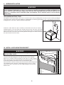
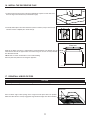
6. PREPARE THE OPENING
CAUTION
Never use a hammer and screwdriver to remove the vertical or horizontal discharge knock-out; this would damage
the hood internal parts.
1 2
1
2
HR0068
VERTICAL DISCHARGE:
HORIZONTAL DISCHARGE:
VERTICAL DISCHARGE
Using long nose pliers, remove the knock-out located on the top of the
hood.
See illustrations at right.
HORIZONTAL DISCHARGE
Using long nose pliers, remove the knock-out located at the back of the
hood.
See illustrations at right.

7
7. BLOWER REMOVAL (HORIZONTAL DISCHARGE ONLY)
These range hoods are factory shipped with the blower mounted for a vertical discharge configuration. For a horizontal discharge
configuration, disassemble the blower from the inner top of the hood (see procedure below). It will be assembled to the inner back of the
hood once the hood is mounted on the wall.
2) Using a 5/16” socket, or a Robertson or a Phillips no. 2 screwdriver,
remove the 4 blower mounting screws (2 on each side) from the inner
top of the hood. Set the blower and screws aside.
1) Unplug the blower.
HD0386
RIGHT SIDE MOUNTING
SCREW LOCATIONS
HD0385
LEFT SIDE MOUNTING
SCREW LOCATIONS
HE0123
8. INSTALL THE ADAPTER/DAMPER
HORIZONTAL DISCHARGE
Mount the 3¼” x 10” adapter/damper to the back of the hood using
2 no. 8 x 3/8” screws (included). Seal the adapter/damper to the hood using
metal foil duct tape.
NOTE: The wall ducting must be properly prepared to receive the adapter.
Before performing the installation, make sure the adapter fits easily
in the duct.
HJ0062
SCREW LOCATIONS
VERTICAL DISCHARGE
Mount the 3¼” x 10” adapter/damper to the top of the hood using 2 no. 8 x 3/8” screws
(included). Seal the adapter/damper to the hood using metal foil duct tape.
HJ0065
SCREW LOCATIONS

8
9. WIRING INSTALLATION
WARNING
!
Improper grounding can result in a risk of electric shock. Consult a qualified electrician if the grounding instructions
are not completely understood, or if there is any doubt as to whether the appliance is properly grounded. Do not
use an extension cord. If the power supply cord is too short, have a qualified electrician install an outlet near the
appliance, in accordance with all applicable codes and standards. Turn off electrical power at service entrance
before wiring.
GROUNDING INSTRUCTIONS
This appliance must be grounded. In the event of an electrical short circuit, grounding reduces the risk of electric shock by providing an
escape wire for the electric current. This appliance is equipped with a cord having a grounding wire with a grounding plug. The plug must
be plugged into an outlet that is properly installed and grounded.
Position the outlet within the space covered by the decorative flue. Place the outlet at a
maximum distance of 24” (from where the cord exits from the hood). The center of the outlet
must be positioned at 3½”
from the center of the future hood location (as illustrated beside).
Make sure this does not interfere with a mounting bracket fastening area or with the decorative
flue (where the flue touches the wall).
HE0064A
10. INSTALL HOOD MOUNTING BRACKET
Construct wood wall framing that is even with the surface of the wall studs.
Make sure to assemble wood wall framing to wall studs for a solid installation.
Make sure the height of the framing will allow the mounting bracket to be secured
to the framing within the dimensions shown (see illustration at right).
After wall surface is finished, carefully center and level the hood mounting bracket
over installation location. Secure it to wall framing using 3 no. 8 x 1½” screws.
Using a level, draw a vertical line up to the ceiling starting from the mounting
bracket center.
WARNING
!
When cutting or drilling into wall, do not damage electrical wiring
and other hidden utilities.
HD0567A
WALL STUDS
FRAMING BEHIND DRYWALL

9
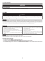
11. INSTALL UPPER FLUE MOUNTING BRACKET
12. INSTALL THE HOOD
Center the upper flue mounting bracket with the center line previously
drawn in step 10 and place it flush with the ceiling.
Use the upper flue mounting bracket as a template to mark the position of
its screws.
Drill the 3 screw holes using a 3/16” drill bit.
Insert the included drywall anchors into the drilled holes (1 per hole).
Secure the upper flue bracket to the wall using 3 no. 8 x 3/4” screws.
Ensure that the bracket is tight against the wall.
CAUTION
DO NOT REMOVE the protective plastic film covering the decorative flue (upper & lower) yet.
1. Align the hood and center it above the hood mounting bracket. Gently lower
the hood until it securely engages the bracket, and slightly pull it downward
to make sure it is fully engaged.
2. Level the hood.
3. Mark the position of both holes located inside lower back of hood (as shown
at right). Also mark the position of 2 of the 6 available upper holes (one on
each side). Remove the hood. Drill through both lower holes using a 3/16”
drill bit. Insert the included drywall anchors into both lower drilled holes. Align
the hood and center it above the hood mounting bracket. Gently lower the
hood until it securely engages the bracket, and slightly pull it downward to
make sure it is fully engaged.
NOTE: For horizontal discharge only, make sure the adapter/damper enters
the duct opening and seal joint from inside the hood using 2” metal foil
duct tape.
4. Secure the hood to the wall using 2 no. 8 x 3/4” screws for lower holes, and 2 no. 8 x 1½ for upper holes.
SCREW LOCATIONS
HD0377
C
L
CEILING
MOUNTING BRACKET
EVEN WITH CEILING
WARNING
!
BE CAREFUL when installing the decorative flue and hood, they may have sharp edges.
HD0417A
LOWER HOLES LOCATION
UPPER HOLES LOCATION
Ø 3/16” TYP.
SIDE VIEW
NOTE: ILLUSTRATION ABOVE REPRESENTS HORIZONTAL EXHAUST
CONFIGURATION, BUT IT ALSO APPLIES TO VERTICAL
EXHAUST CONFIGURATION.
13. REINSTALL THE BLOWER (HORIZONTAL DISCHARGE ONLY)
1. Position the blower on the inner back of the hood, as shown on the right.
2. Using a 5/16” socket, or a Robertson or a Phillips no. 2 screwdriver and the 4 screws previously
removed, secure the blower to the hood.
NOTE: In order to ease installation, before mounting the blower, prepare the screw holes by
screwing all 4 screws without the blower, then remove and mount the blower.
3. Plug the blower connector back in and plug hood power cord into the outlet.
HD1105
CAUTION
Make sure that the screws are well tightened before continuing the installation.

10
14. DUCT CONNECTION (VERTICAL DISCHARGE ONLY)
1. Plug hood power cord into the outlet.
2. Slide the duct over the adapter/damper on the hood.
3. Use metal foil duct tape to seal the joint.
NOTE: If a transition to 7” or 8” round duct is used (not included), it is recommended to
place it at least 18” away from the adapter/damper.
HJ0190
15. PREPARE DECORATIVE FLUE
HO0271
LOWER FLUE
REAR NOTCH
Remove protective plastic film covering the lower flue only.
Peel off both corners at the top of the upper flue (note that upper part has one hole on left and right
sides; see illustration on the right).
Position the lower flue rear notches down.
Gently slide upper flue inside lower flue.
Both lower and upper flues are included with the hood, but for a 10-foot ceiling, discard the provided
upper flue and use the optional flue extension model AEWCB3SB (sold separately).

11
16. INSTALL THE DECORATIVE FLUE
1. To prevent the flue from moving, affix the included foam squares on both sides near
the front edge of the blower box (as illustrated at right).
2. Carefully slide in place decorative lower flue (notches end first) on top of the hood (1)
until flue notches completely fit in hood slots (2).
HO0192
HO0187
12
Slide up the upper flue until it is aligned with its mounting bracket. The bracket must be
inside the flue. Secure the upper flue to its bracket using 2 no. 8 x 3/8” screws (included).
See illustration beside.
NOTE: Duct not shown in illustration to ease understanding.
Remove protective plastic film covering the upper flue.
HO0140
UPPER FLUE MOUNTING BRACKET
FRONT VIEW
UPPER
FLUE
17. REINSTALL HYBRID FILTERS
CAUTION
Remove protective plastic film covering filters before reinstalling them.
Rest rear filters edge on filter springs in the range hood. Tilt up the filters into position.
Make sure filter tabs are securely engaged in range hood front edge slots after installation.
HO0351
FILTER TABS

12
18. LED LIGHTING
!
WARNING
Do not touch lamps during or soon after operation. Burns may occur. Cannot be replaced by any other type of light
bulb or LED module.
The lighting of WCB3I Series range hood is produced by two LED modules (included).
19. CARE
WARNING
!
Before servicing or cleaning the unit, switch power off at service panel and lock service panel to prevent power
from being switched on accidentally. When the service disconnecting means cannot be locked, securely fasten a
prominent warning device, such as a tag, to the service panel.
STAINLESS STEEL
GLASS PANEL
Hot water with mild soap or glass cleaner is all that is usually needed.
When using mild soap, rinse with clear water. Wipe dry with a clean, soft cloth to avoid water marks.
Avoid when choosing a detergent:
- Any cleaners that contain bleach. They will attack stainless steel.
- Any products containing: chloride, fluoride, iodide, bromide. They will deteriorate surfaces rapidly.
- Any combustible products used for cleaning such as acetone, alcohol, ether, benzol, etc. They are highly explosive and should never
be used close to a range.
Do:
• Regularly wash with clean cloth or rag soaked with warm water
and mild soap or liquid dish detergent.
• Always clean in the direction of original polish lines.
• Always rinse well with clear water (2 or 3 times) after cleaning.
Wipe dry completely.
• You may also use a specialized household stainless steel
cleaner
Don’t:
• Use any steel or stainless steel wool or any other scrapers to
remove stubborn dirt.
• Use any harsh or abrasive cleansers.
• Allow dirt to accumulate.
• Let plaster dust or any other construction residues reach the
hood. During construction/renovation, cover the hood to make
sure no dust sticks to stainless steel surfaces.
HYBRID FILTERS
Hybrid filters should be cleaned monthly. Remove hybrid filters by pushing them towards the back of the hood and flipping them downward.
Use a warm detergent solution to clean the filters. Let them dry and reinstall them. Hybrid filters are dishwasher safe. Clean all-metal filters
in the dishwasher using a non-phosphate detergent. Discoloration of the filter may occur if using phosphate detergent or as a result of local
water conditions — but this will not affect filter performance. This discoloration is not covered by the warranty.

13
20. OPERATION
Always turn your hood on before you begin cooking to establish an airflow in the kitchen. Let the blower run for a few minutes to clear the
air after you turn off the range.
CAUTION
After a power failure or during the range hood power up, a 5-second booting sequence is executed. Wait for the
control backlighting to turn off before use.
HC0052
A
B
CD
A. DELAY BUTTON/CONTROL LOCK (DOUBLE FUNCTION BUTTON):
i. When a blower speed is selected, press this button to activate the delay function. The delay button will light to its high intensity, then
to its mid intensity to indicate this function is activated; the selected blower speed button will alternate every 2 seconds between its
high intensity and its mid intensity. The blower will continue to operate for 5 minutes and will stop automatically. Selecting another
speed while the delay function is activated will not deactivate the function or reset the timer. To cancel the delay function, press the
delay button once again, or press the selected speed button which will also turn the blower off.
ii. When the blower is off, it is possible to lock the control interface in order to clean the glass panel.
To lock the control interface: Press and hold this button for 2 seconds. The button will light to its high intensity and flash three times,
it will then stay on its mid intensity to indicate that the control interface is locked.
To unlock the control interface: Press and hold this button for 2 seconds. The button will light to its high intensity and flash 3 times,
it will then fade out to its low intensity to indicate that the control interface is unlocked.
B. SPEED SELECTION BUTTONS:
Press the button corresponding to the desired blower speed (from 1 for low speed to 4 for high speed). The chosen speed button will
light to its high intensity then fade to its mid intensity. To turn off the blower, press once more on the corresponding blower speed
button; the button light will fade to its low intensity.
NOTE: When blower is off, pressing on blower speed 1 button will cause the blower to start on second speed for a very short lapse of
time, and then resume to speed 1.
C. MASTER ON/OFF:
When the blower and lights are off, press this button to turn the hood on to the last memorized speed level and light intensity. If there
are no memorized speed level and light intensity, speed will be set at level 1 and light intensity at 3. To turn off the blower and the
light simultaneously, press this button once.
HEAT SENTRY™: The hood is equipped with a HEAT SENTRY thermostat. If blower is ON at a lower speed setting and excessive heat is
detected above the cooking surface, it turns the blower up to third speed. When the temperature level drops to normal,
the blower will return to its original setting.
NOTE: When Heat Sentry is activated, the “DELAY OFF” function is inactivated.
WARNING
VQ0010
!
The Heat Sentry can change the blower speed when excessive heat is detected above the cooking surface. If this
situation occurs and you must stop the blower, press on the third speed button or on the master ON/OFF button.
D. LIGHT BUTTON/BACKLIGHTING COLOR (DOUBLE FUNCTION BUTTON):
i. This button allows three different lighting levels according to your needs. Press once for full intensity, twice for intensity level 2, and
once more for nightlight. To turn off the lights, press once more.
If desired, when the lights are on, press and maintain the light button for 1 second; lights will be turned off.
NOTE: When only the lights are ON to any intensity and no interaction with the hood is detected for a 10-second period, the 7 buttons
backlighting will fade to its low intensity, acting as a night light feature.
ii. When lights are off, pressing and holding this button for 1 second will switch the backlighting color from white to blue or from blue
to white (default backlighting color is white) and memorize it. The button will flash three times to indicate that the color change has
been made.
NOTE: Due to the particular sensitivity of the control interface, keep the glass panel clean as dirt and condensation may cause erratic
operation of the hood blower and/or lighting. If this situation occurs, wipe the glass panel and wait 90 seconds. Then, adjust the
blower and/or lighting at your convenience.

14
21. WIRING DIAGRAM
Line
Neutral
Ground
120 V AC
BLK BLACK
BLU BLUE
BRN BROWN
GRN GREEN
GRY GREY
ORG ORANGE
RED RED
WHT WHITE
YEL YELLOW
COLOR CODE
16 Pins
LED driver
Input
Output
LED
LED
User interface
T1 (10 VAC)
J13
FAN MOTOR
1
3
2
5
4
J12
User Interface
J1
10VAC
J8
Aux. Input
3
2
1
RP1
J3
Programmer
header
Triac Ext
J7
J11
12VDC
+
-
J4
Motor
Speed
J2
120V-Motor-Lamp
1
J10
J9 Serial Com
5
4
32
1
J5
Output
J6
External
Triac
2
3
4
5
1
2
3
4
1
2
1
2
1
2
3
4
1
2
3
1
2
YEL
BLK
BLK
WHT
WHT
WHT
RED
RED
RED
BLU
WHT
ORG
BLK
WHT
BLK
WHT
RED
RED
WHT
BLK
WHT
RED
GRY
BRN
BLU
WHT
ORG
BLK
HE0065A
WARNING
VQ0010
!
Risk of electric shock. Electrical wiring must be done by qualified personnel in accordance with all applicable
codes and standards. Before connecting wires, switch power off at service panel and lock service disconnecting
means to prevent power from being switched on accidentally.

15
REPLACEMENT PARTS AND REPAIRS
In order to ensure your unit remains in good working condition, you must use Broan-NuTone genuine replacement parts only. Broan-NuTone genuine
replacement parts are specially designed for each unit and are manufactured to comply with all the applicable certification standards and maintain a high
standard of safety. Any third party replacement part used may cause serious damage and drastically reduce the performance level of your unit, which
will result in premature failing. Broan-NuTone recommends to contact a certified service depot for all replacement parts and repairs.
22. SERVICE PARTS
KEY
NO.
PART NO.DESCRIPTION
QTY. (HOOD WIDTH)
30” 36”
1
SV09955XX* G
LASS PANEL 30" 1
SV09956XX* G
LASS PANEL 36" 1
2 SV22427 ELECTRONIC CONTROL 11
3 SV09022 TRANSFORMER 11
4 62612 LED MODULE (1) 2 2
5 SV62053 HYBRID FILTER 15.875" X 14" X 0.5" (1) 2 2
6 SV08582 I
NTERNAL BLOWER 11
7 62248 LED DRIVER AND CONNECTION HARNESS 11
8 SV21189 POWER UNIT 11
9 SV09014 HOOD MOUNTING BRACKET 11
10 SV13296 ADAPTER/DAMPER 11
11 SV19134 UPPER FLUE 11
12 SV19135 UPPER FLUE MOUNTING BRACKET 11
13 SV19133 LOWER FLUE 11
** SV23894 CRT KIT 300 CFM (OPTIONAL)11
** SV23865 I
NSTALLATION MANUAL 11
** SV09027 PARTS BAG 11
** SV05869 BEST LOGO 11
* P
ART NUMBER ACCORDING TO GLASS PANEL COLOR AND SIZE.
PLEASE CONTACT CUSTOMER SERVICE OR VISIT OUR WEB SITE.
1
2
3
4
5
6
7
8
9
10
11
12
13
HL0227
** ITEM NOT SHOWN.

16
23. WARRANTY
FIVE-YEAR LIMITED WARRANTY FOR BEST
®
PRODUCTS
Warranty Period and Exclusions: Broan-NuTone, LLC (the “Company”) warrants to the consumer purchaser of its product (“you”) that the product (the
“Product”) will be free from material defects in the materials or its workmanship for a period of five (5) years from the date of original purchase (or such
longer period as may be required by applicable law) or a period of two (2) years from the date of service for any labor provided on the Product.
The limited warranty period for any replacement parts provided by the Company and for any Products repaired or replaced under this limited warranty shall
be the remainder of the original warranty period (or such longer period as may be required by applicable law).
THIS WARRANTY DOES NOT EXTEND TO FLUORESCENT LAMP STARTERS, TUBES AND BULBS, FUSES, FILTERS, DUCTS, ROOF CAPS, WALL CAPS
AND OTHER ACCESSORIES FOR DUCTING. This warranty does not cover (a) normal maintenance and service, (b) normal wear and tear, (c) any Products or
parts which have been subject to misuse, abuse, abnormal usage, negligence, accident, improper or insufficient maintenance, storage or repair (other than
repair by the Company), (d) damage caused by faulty installation, or installation or use contrary to recommendations or instructions, (f) damage caused by
exposure to salt air, (g) damage in transit, (h) natural wear of finish, (i) Products in commercial or nonresidential use, (j) damage caused by fire, flood or
other act of God, or (k) Products with altered, defaced or removed serial numbers. This warranty covers only Products sold to consumers in North America.
This warranty supersedes all prior warranties and, subject to applicable law, is not transferable from the original consumer purchaser.
No Other Warranties: This Limited Warranty contains the Company’s sole obligation and your sole remedy for defective Products. The foregoing warranties
are exclusive and in lieu of any other warranties and conditions, express or implied. TO THE MAXIMUM EXTENT PERMITTED BY APPLICABLE LAW, THE
COMPANY DISCLAIMS AND EXCLUDES ALL OTHER EXPRESS WARRANTIES AND CONDITIONS, AND DISCLAIMS AND EXCLUDES ALL WARRANTIES
AND CONDITIONS IMPLIED BY LAW, INCLUDING WITHOUT LIMITATION THOSE OF MERCHANTABILITY AND FITNESS FOR A PARTICULAR PURPOSE.
To the extent that applicable law prohibits the exclusion of implied warranties or conditions, the duration of any applicable implied warranty or condition
is limited to the period specified for the express warranty above. Some jurisdictions (which may include the Province of Quebec or specific US states) do
not allow limitations on how long an implied warranty lasts, so the above limitation may not apply to you. Any oral or written description of the Product is
for the sole purpose of identifying it and shall not be construed as an express warranty.
Whenever possible, each provision of this Limited Warranty shall be interpreted in such manner as to be effective and valid under applicable law, but if any
provision is held to be prohibited or invalid, such provision shall be ineffective only to the extent of such prohibition or invalidity, without invalidating the
remainder of such provision or the other remaining provisions of the Limited Warranty.
Remedy: During the applicable limited warranty period, the Company will, at its option, provide replacement parts for, or repair or replace, without charge,
any Product or part thereof, to the extent the Company finds it to be covered by and in breach of this limited warranty under normal use and service. The
Company will ship the repaired or replaced Product or replacement parts to you at no charge. You are responsible for all costs for removal, reinstallation
and shipping, insurance or other freight charges incurred in the shipment of the Product or part to the Company. If you must send the Product or part
to the Company, as instructed by the Company, you must properly pack the Product or part—the Company is not responsible for damage in transit. The
Company reserves the right to utilize reconditioned, refurbished, repaired or remanufactured Products or parts in the warranty repair or replacement
process. Such Products and parts will be comparable in function and performance to an original Product or part and warranted for the remainder of the
original warranty period (or such longer period as may be required by applicable law).
Company reserves the right, in its sole discretion, to refund the money actually paid by you for the Product. If the Product or component is no longer
available, replacement may be made with a similar product of equal or greater value, at Company’s sole discretion. This is your sole and exclusive remedy
for breach of this limited warranty.
Exclusion of Damages: THE COMPANY’S OBLIGATION TO PROVIDE REPLACEMENT PARTS, OR REPAIR OR REPLACE, AT THE COMPANY’S OPTION,
SHALL BE YOUR SOLE AND EXCLUSIVE REMEDY UNDER THIS LIMITED WARRANTY AND THE COMPANY’S SOLE AND EXCLUSIVE OBLIGATION. THE
COMPANY SHALL NOT BE LIABLE FOR INCIDENTAL, INDIRECT, CONSEQUENTIAL OR SPECIAL DAMAGES ARISING OUT OF OR IN CONNECTION WITH
THE PRODUCT, ITS USE OR PERFORMANCE.
Some jurisdictions do not allow the exclusion or limitation of incidental or consequential damages, so the above limitation or exclusion may not apply
to you. This warranty gives you specific legal rights, and you may also have other rights, which vary from jurisdiction to jurisdiction. The disclaimers,
exclusions, and limitations of liability under this warranty will not apply to the extent prohibited by applicable law.
This warranty covers only replacement or repair of defective Products or parts thereof at the Company’s main facility and does not include the cost of field
service travel and living expenses.
Any assistance the Company provides to or procures for you outside the terms, limitations or exclusions of this limited warranty will not constitute a waiver
of such terms, limitations or exclusions, nor will such assistance extend or revive the warranty. The Company will not reimburse you for any expenses
incurred by you in repairing or replacing any defective Product, except for those incurred with the Company’s prior written permission.
How to Obtain Warranty Service: To qualify for warranty service, you must (a) notify the Company at the address or telephone number stated below within
seven (7) days of discovering the covered defect, (b) give the model number and part identification and (c) describe the nature of any defect in the Product
or part. At the time of requesting warranty service, you must present evidence of the original purchase date. If you cannot provide a copy of the original
written limited warranty, then the terms of the Company’s most current written limited warranty for your particular product will control.
PRODUCT SPECIFICATIONS
All illustrations and specifications in this catalog are based on the latest product information available at time of production. Broan-NuTone, LLC and
BEST® reserves the right to make changes at any time, without notice, in prices, colors, materials, equipment, specifications and models, place of
manufacture and to discontinue models or equipment.
Best
Broan-NuTone, LLC- 926 W. State Street, Hartford, WI 53207 1-800-637-1453
Best®, 550 Lemire Blvd., Drummondville, QC, Canada (1-866-737-7770) www.bestrangehoods.com

CONÇUE POUR USAGE RÉSIDENTIEL SEULEMENT
INSTALLATEUR : LAISSER CE GUIDE AU PROPRIÉTAIRE.
PROPRIÉTAIRE : DIRECTIVES D’UTILISATION ET D’ENTRETIEN
AUX PAGES 12 ET 13.
LIRE ET CONSERVER CES DIRECTIVES
! !
SÉRIE WCB3I
HB0046
GUIDE D'INSTALLATION
BEST; Hartford, Wisconsin www.BestRangeHoods.com 800 558-1711
BEST; Drummondville, QC, Canada www.BestRangeHoods.ca 866 737-7770
23865 rév. 03

2
AFIN DE RÉDUIRE LES RISQUES D’INCENDIE,
D’ÉLECTROCUTION OU DE BLESSURES CORPORELLES,
SUIVEZ LES DIRECTIVES CI-DESSOUS :
1. N’utilisez cet appareil que de la façon prévue par le
manufacturier. Si vous avez des questions, contactez le
manufacturier à l’adresse ou au numéro de téléphone indiqués
dans la garantie.
2. Avant de réparer ou de nettoyer l’appareil, couper l’alimentation
électrique en verrouillant le panneau de distribution afin
d’éviter sa remise en marche accidentelle. Si le panneau de
distribution ne peut être verrouillé, y fixer un avertissement en
évidence, telle qu’une étiquette de couleur vive.
3. Les travaux d’installation et de raccordement électrique doivent
être effectués par une personne qualifiée, conformément
aux codes et aux standards de construction, incluant ceux
concernant la protection contre les incendies.
4. Une quantité d’air adéquate est requise afin d’assurer une
bonne combustion et l’évacuation des gaz par la cheminée
dans le cas des équipements alimentés au gaz afin de
prévenir les retours de cheminée. Suivez les instructions et
conformez-vous aux standards de sécurité des manufacturiers
d’équipement de chauffage, tel qu’ils sont publiés par la
National Fire Protection Association (NFPA) et l’American
Society for Heating, Refrigeration and Air Conditioning
Engineers (ASHRAE) ainsi que les responsables des
codes locaux.
5. Veillez à ne pas endommager le câblage électrique ou d’autres
équipements non apparents lors de la découpe ou du perçage
du mur ou du plafond.
6. Les ventilateurs avec conduits doivent toujours évacuer l’air
à l’extérieur.
7. Ne pas utiliser cet appareil avec une commande de vitesse à
semi-conducteur additionnelle.
8. Afin de réduire les risques d’incendie, n’utilisez que des conduits
de métal.
9. Cet appareil doit être mis à la terre.
10. Lorsqu’une réglementation est en vigueur et qu’elle comporte
des exigences d’installation et/ou de certification plus
restrictives, lesdites exigences prévalent sur celles de ce
document et l’installateur entend s’y conformer à ses frais.
AFIN DE RÉDUIRE LES RISQUES DE FEU DE
CUISINIÈRE :
a) Ne jamais laisser les appareils de cuisson sans surveillance
lorsqu’ils sont réglés à feu vif. Les débordements engendrent
de la fumée et des déversements graisseux pouvant
s’enflammer. Chauffez l’huile lentement, à feu doux ou moyen.
b) Mettez toujours la hotte en marche lorsque vous cuisinez à feu
vif ou que vous cuisinez des mets flambés (par ex. : crêpes
Suzette, cerises jubilées, steaks au poivre flambés).
c) Nettoyez régulièrement le ventilateur. Ne laissez pas la graisse
s’accumuler sur le ventilateur, les filtres ou les conduits
d’évacuation.
d) Utilisez le bon format de casserole. Servez-vous toujours de
casseroles et d’ustensiles appropriés à la dimension de la
surface chauffante.
1. Pour une utilisation à l’intérieur seulement.
2. Pour usage domestique seulement. Ne pas utiliser pour évacuer
des vapeurs ou des matières dangereuses ou explosives.
3. Afin d’éviter tout dommage au moteur ou de déséquilibrer
ou de rendre bruyante la roue du moteur, garder votre
appareil à l’abri des poussières de gypse et de construction/
rénovation,etc.
4. Le moteur de votre hotte possède une protection thermique
qui arrêtera automatiquement le moteur s’il surchauffe. Le
moteur redémarrera automatiquement une fois refroidi. Si le
moteur continue à arrêter et à redémarrer, faites-le vérifier.
5. Pour une meilleure évacuation des odeurs de cuisson, le
bas de votre hotte devrait être situé à un minimum de 24 po
(30 po pour une cuisinière à gaz) et à un maximum de 30 po
au-dessus de la table de cuisson.
6. Deux installateurs sont recommandés lors de l’installation vu
la grande dimension et le poids de cette hotte.
7. Afin de réduire les risques d’incendie, assurez-vous d’évacuer
l’air à l’extérieur. Ne pas évacuer l’air dans des espaces
restreints comme l’intérieur des murs ou plafonds ou dans le
grenier, faux plafond ou garage.
8 En raison de la grande capacité d’évacuation de cette hotte,
il est recommandé d’ouvrir une fenêtre dans ou près de la
cuisine afin de remplacer l’air évacué.
9. Afin de réduire les risques d’incendie et d’électrocution, la
hotte Best de la série WCB3I ne doit être installée qu'avec son
ventilateur intérieur intégré.
10. Veuillez consulter l’autocollant apposé à l’intérieur de la hotte
pour plus d’information ou autres exigences.
AVERTISSEMENT
!
ATTENTION
AVERTISSEMENT
!
AFIN D’ÉVITER TOUT RISQUE DE BLESSURES LORS
D’UN FEU DE CUISINIÈRE, SUIVEZ CES DIRECTIVES* :
1. Étouffez les flammes avec un couvercle hermétique,
une tôle à biscuits ou un plateau métallique et ensuite,
éteindre le brûleur. PRENEZ SOIN D’ÉVITER LES
BRÛLURES. SI LES FLAMMES NE S’ÉTEIGNENT PAS
IMMÉDIATEMENT, ÉVACUEZ LES LIEUX ET APPELEZ
LES POMPIERS.
2. NE PRENEZ JAMAIS UNE CASSEROLE EN FLAMMES
DANS VOS MAINS. Vous pourriez vous brûler.
3. N’UTILISEZ PAS D’EAU, incluant un linge à vaisselle ou une
serviette mouillée, cela pourrait occasionner une violente
explosion de vapeur.
4. N’utilisez un extincteur QUE DANS LE CAS OÙ :
A. Vous savez qu’il s’agit d’un extincteur de classe ABC et
que vous en connaissez le fonctionnement.
B. Le feu est petit et limité
à l’endroit où il a débuté.
C. Les pompiers ont été avisés.
D. Vous pouvez combattre le feu en ayant accès à une sortie
de secours.
*Tirées du Kitchen Fire Safety Tips publié par la NFPA.

3
HL0226
SYSTÈME DE HOTTE DE CUISINIÈRE DE SÉRIE WCB3I
MODÈLE 639
(CAPUCHON
MURAL DE
3¼ PO X 10 PO)
MODÈLE 634
OU 644
(CAPUCHON
DE
TOIT)
M
ODÈLE 639
(CAPUCHON
MURAL DE
3¼ PO X 10 PO)
(C
OUDE
OPTIONNEL
DE
3¼ PO X 10 PO)
(CONDUIT
STANDARD
DE
3¼ PO X 10 PO)
ADAPTATEUR/VOLET DE
3¼ PO X 10 PO
(INCLUS AVEC LA HOTTE)
POUR ÉVACUATION HORIZONTALE
OU VERTICALE
CONDUIT
DÉCORATIF
SUPÉRIEUR
CONDUIT
DÉCORATIF
INFÉRIEUR

4
TABLE DES MATIÈRES
1. I NSTALLATION DES CONDUITS ....................................................................................................................................................4
2. PRÉPARATION DE L'INSTALLATION ...............................................................................................................................................5
3. CHOIX DU TYPE D'INSTALLATION ................................................................................................................................................5
4. R
ETRAIT DES FILTRES HYBRIDES ...............................................................................................................................................5
5. INSTALLATION DE LA FAÇADE DE VERRE (MODÈLES SBN SEULEMENT) ................................................................................................6
6. PRÉPARATION DE L'OUVERTURE ................................................................................................................................................6
7. R ETRAIT DU VENTILATEUR (ÉVACUATION HORIZONTALE) ..................................................................................................................7
8. INSTALLATION DE L'ADAPTATEUR/DU VOLET ..................................................................................................................................7
9. INSTALLATION ÉLECTRIQUE .......................................................................................................................................................8
10. INSTALLATION DU SUPPORT DE MONTAGE DE LA HOTTE ..................................................................................................................8
11. INSTALLATION DU SUPPORT DE MONTAGE DU CONDUIT DÉCORATIF SUPÉRIEUR ....................................................................................9
12. INSTALLATION DE LA HOTTE ......................................................................................................................................................9
13. RÉINSTALLATION DU VENTILATEUR (ÉVACUATION HORIZONTALE) ........................................................................................................9
14. INSTALLATION DU CONDUIT (ÉVACUATION VERTICALE) ................................................................................................................... 10
15. PRÉPARATION DU CONDUIT DÉCORATIF .....................................................................................................................................10
16. INSTALLATION DU CONDUIT DÉCORATIF ...................................................................................................................................... 11
17. RÉINSTALLATION DES FILTRES HYBRIDES ................................................................................................................................... 11
18. ÉCLAIRAGE À DEL ..............................................................................................................................................................12
19. ENTRETIEN .........................................................................................................................................................................12
20. FONCTIONNEMENT ...............................................................................................................................................................13
21. SCHÉMA ÉLECTRIQUE ...........................................................................................................................................................14
22. PIÈCES DE REMPLACEMENT ...................................................................................................................................................15
23. GARANTIE ..........................................................................................................................................................................16
Planifier à quel endroit et de quelle façon les conduits seront installés.
Le conduit reliant cette hotte à l’extérieur du bâtiment a un effet direct sur le débit de l’air, le bruit
généré et la consommation d’énergie de son ventilateur. Pour obtenir le meilleur rendement,
utiliser un conduit le plus droit et le plus court possible, en évitant de raccorder le ventilateur de
la hotte à un conduit de format plus petit que recommandé. De l’isolant autour du conduit peut
réduire la perte d’énergie et empêcher la croissance de moisissures. Les hottes installées avec
un conduit préexistant pourraient ne pas atteindre leur débit nominal. Veuillez vous référer au
tableau ci-dessous pour vous aider à planifier l'installation la plus efficace.
Installer un capuchon de toit ou de mur, puis s'assurer qu'il n'y a aucune fuite dans l'isolation de
la maison. Relier le conduit de métal au capuchon, puis acheminer le conduit jusqu’à la hotte.
Sceller les joints avec du ruban adhésif de métal de 2 po de largeur.
Il est recommandé d’installer la hotte à une distance minimale de 24 po au-dessus d’une
cuisinière électrique et de 30 po au-dessus d’une cuisinière au gaz.
Une distance de plus de 36 po demeure à la discrétion de l’installateur et de l’utilisateur.
*Une rallonge de conduit décoratif est requise pour les plafonds de 10 pi, modèle n° AEWCB3SB (vendue séparément).
1. INSTALLATION DES CONDUITS
CONDUIT
DE 3¼ PO X 10 PO
C
APUCHON DE TOIT
CONDUIT
DE 3¼ PO X 10 PO
HOTTE
CONDUIT
DÉCORATIF
HH0221F
24 PO MINIMUM
AU-DESSUS DE LA
SURFACE DE CUISSON
(30 PO POUR UNE
CUISINIÈRE AU GAZ)
ADA PTAT E UR /VOLET
DE 3¼ PO X 10 PO
CAPUCHON
DE
MUR
ADA PTAT E UR /VOLET
DE 3¼ PO X 10 PO
HAUTEUR DU PLAFOND 8 PI 9 PI 10 PI*
D
ISTANCE MINIMALE/MAXIMALE RECOMMANDÉE AU-DESSUS
DE LA SURFACE DE CUISSON D'UNE CUISINIÈRE ÉLECTRIQUE
24 PO/30 PO 24 PO/30 PO 24 PO/30 PO
DISTANCE MINIMALE/MAXIMALE RECOMMANDÉE AU-DESSUS
DE LA SURFACE DE CUISSON D'UNE CUISINIÈRE AU GAZ
30 PO/33 PO 30 PO/36 PO 30 PO/36 PO
LONGUEUR MAXIMALE DE
CONDUIT DE
3¼ PO X 10 PO
CAPUCHON DE MUR OU
DE TOIT AVEC CLAPET
COUDE(S)* DE 90°
ET/OU DE 45°
60
PI 10
50
PI 11
40
PI 12
L
ONGUEURS MAXIMALES DE CONDUIT RECOMMANDÉES POUR OBTENIR UNE EFFICACITÉ D'ÉVACUATION DE 80 %
*C
OUDES STANDARDS DE RAYON INTERNE DE 1 PO
La page est en cours de chargement...
La page est en cours de chargement...
La page est en cours de chargement...
La page est en cours de chargement...
La page est en cours de chargement...
La page est en cours de chargement...
La page est en cours de chargement...
La page est en cours de chargement...
La page est en cours de chargement...
La page est en cours de chargement...
La page est en cours de chargement...
La page est en cours de chargement...
La page est en cours de chargement...
La page est en cours de chargement...
La page est en cours de chargement...
La page est en cours de chargement...
La page est en cours de chargement...
La page est en cours de chargement...
La page est en cours de chargement...
La page est en cours de chargement...
La page est en cours de chargement...
La page est en cours de chargement...
La page est en cours de chargement...
La page est en cours de chargement...
La page est en cours de chargement...
La page est en cours de chargement...
La page est en cours de chargement...
La page est en cours de chargement...
-
 1
1
-
 2
2
-
 3
3
-
 4
4
-
 5
5
-
 6
6
-
 7
7
-
 8
8
-
 9
9
-
 10
10
-
 11
11
-
 12
12
-
 13
13
-
 14
14
-
 15
15
-
 16
16
-
 17
17
-
 18
18
-
 19
19
-
 20
20
-
 21
21
-
 22
22
-
 23
23
-
 24
24
-
 25
25
-
 26
26
-
 27
27
-
 28
28
-
 29
29
-
 30
30
-
 31
31
-
 32
32
-
 33
33
-
 34
34
-
 35
35
-
 36
36
-
 37
37
-
 38
38
-
 39
39
-
 40
40
-
 41
41
-
 42
42
-
 43
43
-
 44
44
-
 45
45
-
 46
46
-
 47
47
-
 48
48


Best WCB3I30SBN Guide d'installation
- Catégorie
- Hottes
- Taper
- Guide d'installation
dans d''autres langues
- English: Best WCB3I30SBN Installation guide
- español: Best WCB3I30SBN Guía de instalación
Documents connexes
-
Best UCB3I30SBW Guide d'installation
-
-
Best WC53I30BLS Manuel utilisateur
-
-
 BEST Range Hoods ANKWC23 Guide d'installation
-
-
Best ICB3I36SBN Guide d'installation
-
-
-

